
Tired of being locked-up. Me too.
Just as we were seeing signs that the SARS-CoV-2 thing might be coming to an end, it appears that our county is going to move back into the "extreme" category.
Since we are not a business, anymore, we are only constrained by good sense, but, we have been adhering to the OR Governor's "gathering" guidelines. We don't want to have anything to do with making one of our radio friends sick.
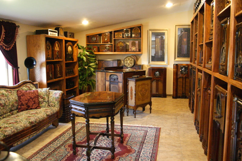
Still, we remain optimistic. We hope that, by June, we will be able to reopen the Radio Shop/Museum to visitors. If we start with small groups, maybe by the middle of summer we can accommodate larger groups and clubs.
At first we will require masks. We will also require a completed Covid vaccination card ( you show me yours and I'll show you mine). Politics are not part of this and we don't care to discuss that aspect anymore - or ever.
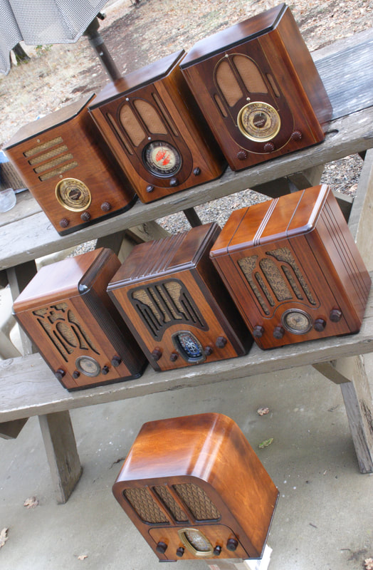
We still have a lot of restored radios sitting around looking for a display spot - or a new home. By mid summer we hope to have a "Radio Shop" sale, possibly attended by other local radio collectors who also have accumulated WAY TOO MUCH STUFF over the last year (or years). Dates will depend on so much - If we have another fire season like last year - you might want to bring a fire-hose.
So - - if you would like to set up a visit, send us a message using the contact form. Or if you already have our email address, use that. Tours are still free. If you have an old radio that needs help, bring it along. Any advise (good or bad) or restoration assistance, is also free of charge.
Looking forward to "normal",
Russ & Sue
Since we are not a business, anymore, we are only constrained by good sense, but, we have been adhering to the OR Governor's "gathering" guidelines. We don't want to have anything to do with making one of our radio friends sick.
Still, we remain optimistic. We hope that, by June, we will be able to reopen the Radio Shop/Museum to visitors. If we start with small groups, maybe by the middle of summer we can accommodate larger groups and clubs.
At first we will require masks. We will also require a completed Covid vaccination card ( you show me yours and I'll show you mine). Politics are not part of this and we don't care to discuss that aspect anymore - or ever.
We still have a lot of restored radios sitting around looking for a display spot - or a new home. By mid summer we hope to have a "Radio Shop" sale, possibly attended by other local radio collectors who also have accumulated WAY TOO MUCH STUFF over the last year (or years). Dates will depend on so much - If we have another fire season like last year - you might want to bring a fire-hose.
So - - if you would like to set up a visit, send us a message using the contact form. Or if you already have our email address, use that. Tours are still free. If you have an old radio that needs help, bring it along. Any advise (good or bad) or restoration assistance, is also free of charge.
Looking forward to "normal",
Russ & Sue

 RSS Feed