
Well - OK, It is going to cost you about $10 to purchase the materials you need at WM. but you will have enough to fix 10 speakers.
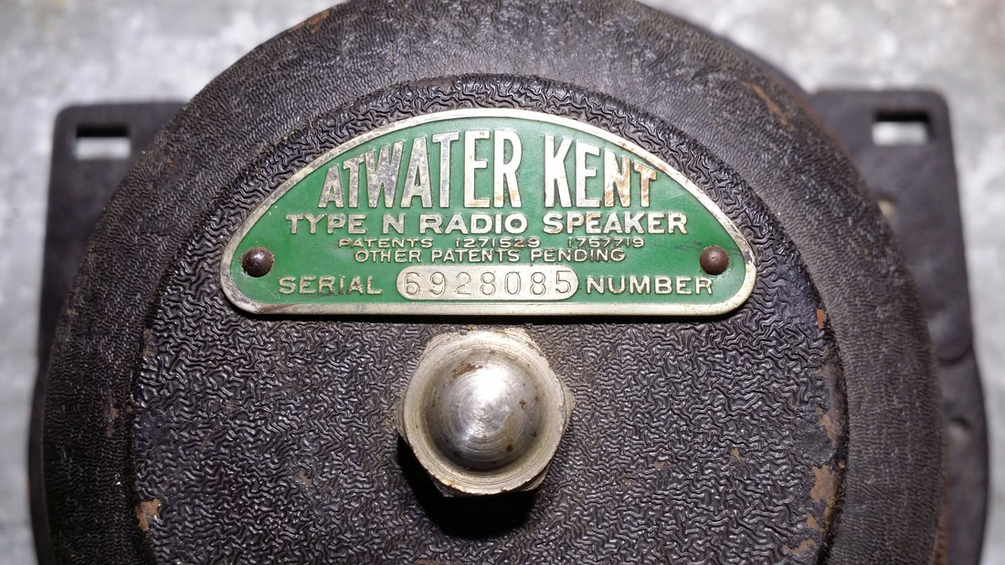
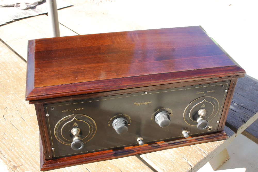
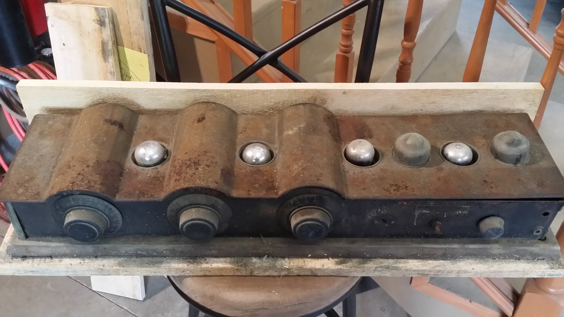
SO, you have an AK Type N that somebody (you) put their finger through or Jr. poked it with a stick or whatever. Now it sounds like a nest of bees trying to put on a concert. You could save money by grabbing a roll of TP and gluing it up in a nice ridged mess that looks like a 2nd grade art project or you could fix it right with about $1 worth of materials available at Walmart.
SO, you have an AK Type N that somebody (you) put their finger through or Jr. poked it with a stick or whatever. Now it sounds like a nest of bees trying to put on a concert. You could save money by grabbing a roll of TP and gluing it up in a nice ridged mess that looks like a 2nd grade art project or you could fix it right with about $1 worth of materials available at Walmart.
This project requires no special tools, just a little patience. I've dome this before (a lot) so I can do it in about an hour. I would expect a first-timer would need 2 - 3 hours
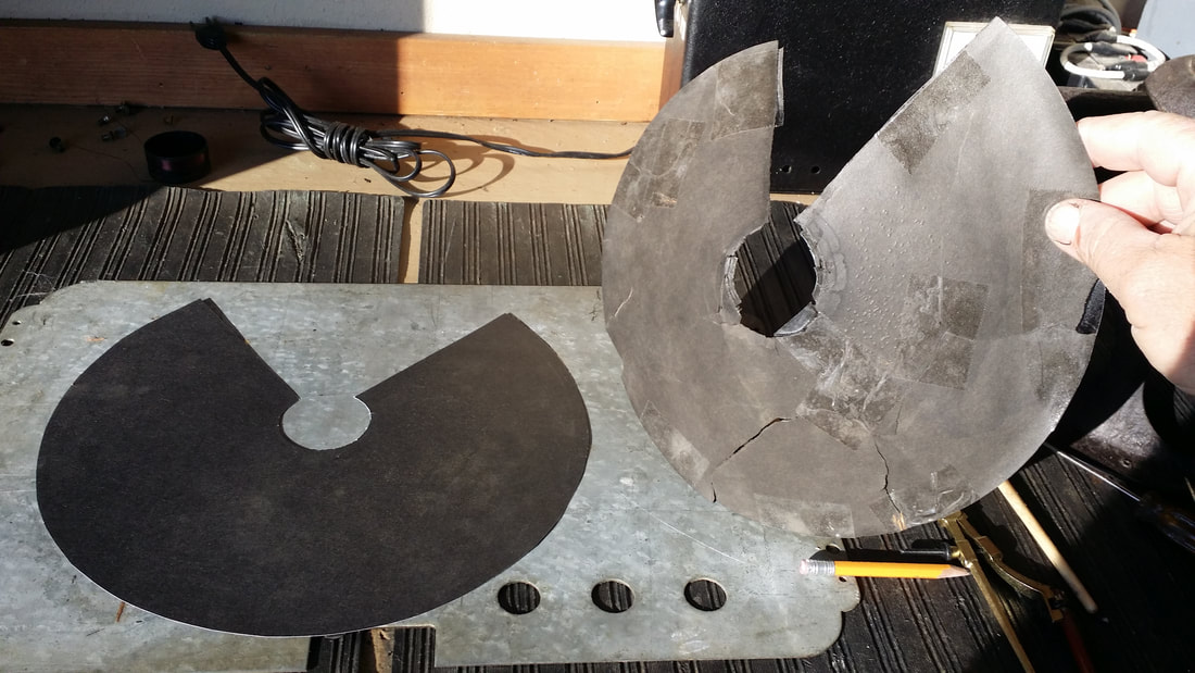
If your cone is ripped or even partially missing, this job is much easier than doing the math required to calculate the shape of a flat piece of material which becomes a cone, SO, take care to preserve as much of the original cone as possible. I will mention here that the diameter of the circular cut-out is about 11" becoming about 8" when the ends are glued forming a cone.
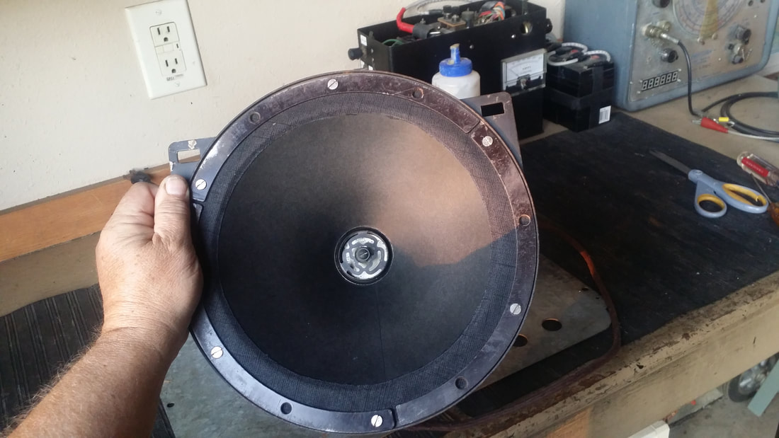
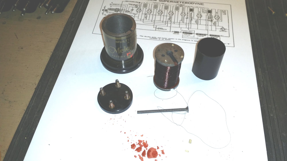
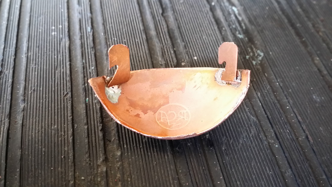
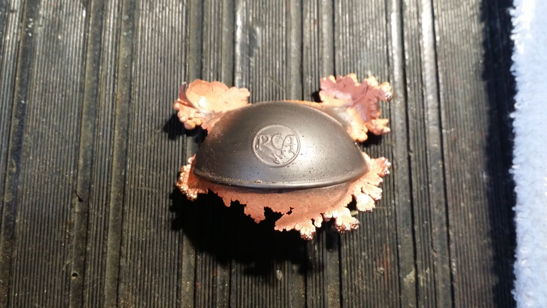
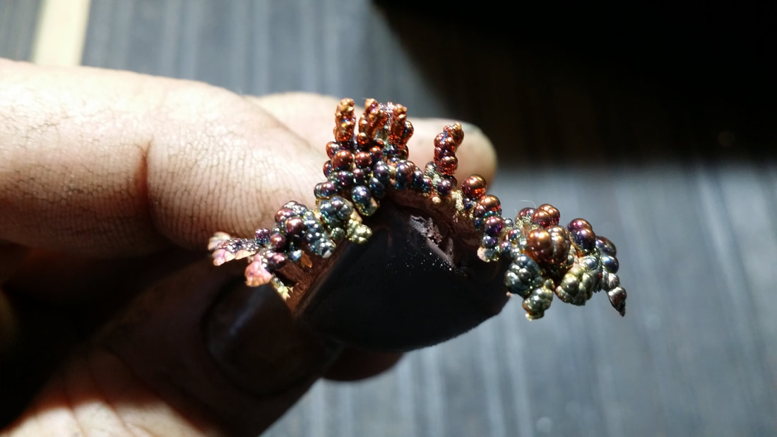
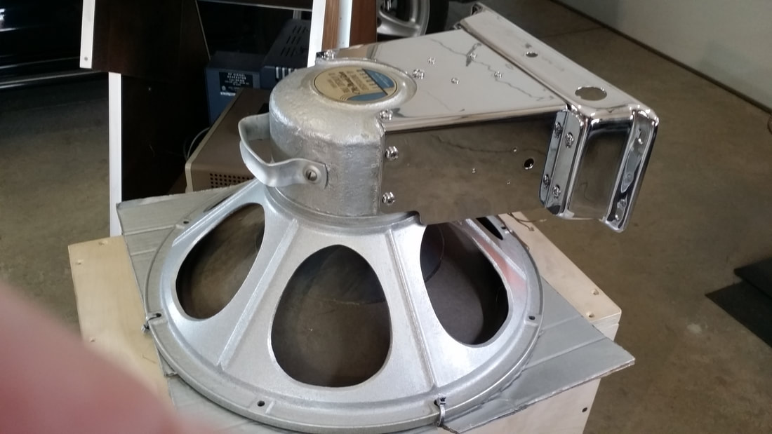
If the spider (metal thing in the center of the cone) or the voice coil (see pic. below) is damage or missing it must be repaired or replaced. This article does not cover VC rewinding or fabricating a new spider.
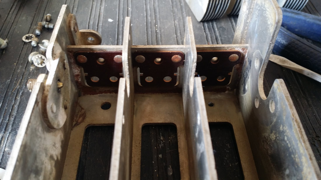
Begin by unsoldering the magnet wire leads going to the voice coil. Then remove the screw holding the spider and the screws holding the metal ring (3 pieces) around the outside edge of the suspension (pictured 2 and 3 below).
Use a scraper to separate the suspension from the basket (speaker frame). Don't worry about keeping the old material intact, but do keep a piece for reference later when you cut out the new suspension.
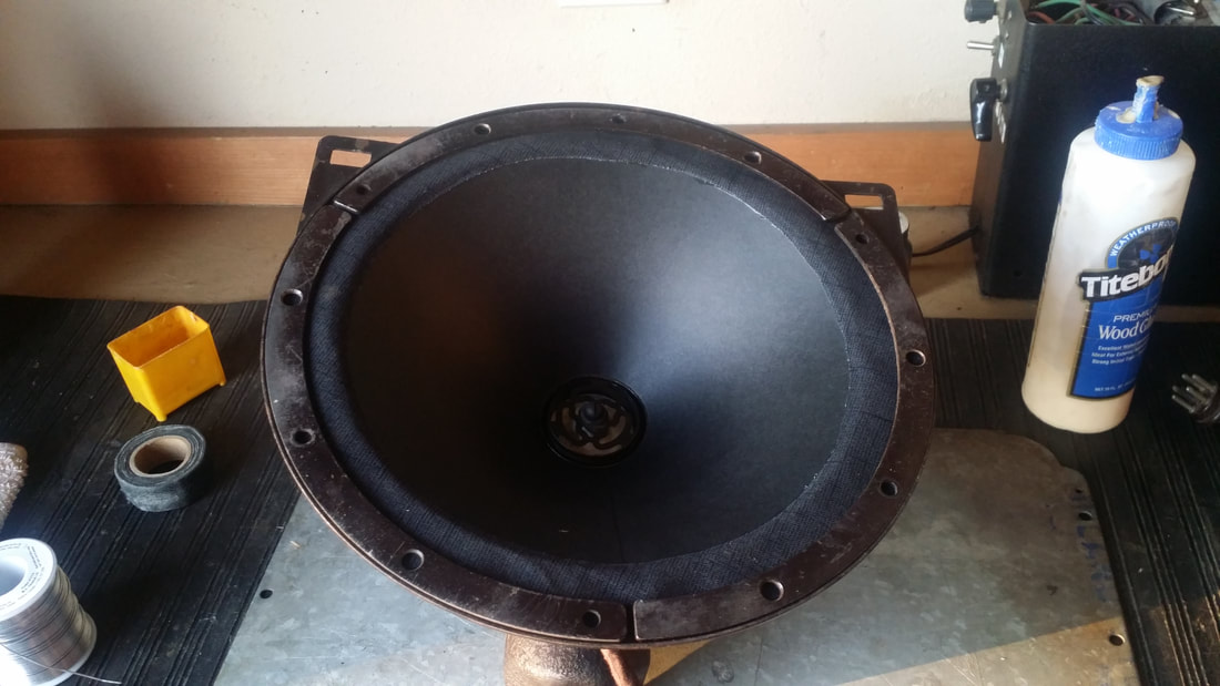
The cone should now be lifted out of the basket with the spider and VC still attached.
Sometimes the VC attachment to the cone is so loose that they fall apart - sometimes not. Again, the object here is to separate the VC and the spider from the old paper cone while keeping the old cone as intact as possible since you are going to use it as a pattern for the new cone.
I have found that brushing on a little lacquer thinner around the edge of the spider can loosen the glue. Basically this is a metal ring pressed into the VC that captures the inner edge of the paper cone between the spider and the VC. Caution: too much solvent (thinner) leaking onto the VC will break down the adhesive holding the coil to the former (round tube). So be careful. In the end you will probably have to scrape some of the old cone material off of the edge of the spider since these areas need to be clean before reattachment.
Next, cut the old cone along the original seam allowing the paper to lay flat. Observe the original overlap and allow for the same overlap on the new cone so that the cone can be formed by gluing the edges together.
If your cone is ripped or even partially missing, this job is much easier than doing the math required to calculate the shape of a flat piece of material which becomes a cone, SO, take care to preserve as much of the original cone as possible. I will mention here that the diameter of the circular cut-out is about 11" becoming about 8" when the ends are glued forming a cone.
If the spider (metal thing in the center of the cone) or the voice coil (see pic. below) is damage or missing it must be repaired or replaced. This article does not cover VC rewinding or fabricating a new spider.
Begin by unsoldering the magnet wire leads going to the voice coil. Then remove the screw holding the spider and the screws holding the metal ring (3 pieces) around the outside edge of the suspension (pictured 2 and 3 below).
Use a scraper to separate the suspension from the basket (speaker frame). Don't worry about keeping the old material intact, but do keep a piece for reference later when you cut out the new suspension.
The cone should now be lifted out of the basket with the spider and VC still attached.
Sometimes the VC attachment to the cone is so loose that they fall apart - sometimes not. Again, the object here is to separate the VC and the spider from the old paper cone while keeping the old cone as intact as possible since you are going to use it as a pattern for the new cone.
I have found that brushing on a little lacquer thinner around the edge of the spider can loosen the glue. Basically this is a metal ring pressed into the VC that captures the inner edge of the paper cone between the spider and the VC. Caution: too much solvent (thinner) leaking onto the VC will break down the adhesive holding the coil to the former (round tube). So be careful. In the end you will probably have to scrape some of the old cone material off of the edge of the spider since these areas need to be clean before reattachment.
Next, cut the old cone along the original seam allowing the paper to lay flat. Observe the original overlap and allow for the same overlap on the new cone so that the cone can be formed by gluing the edges together.
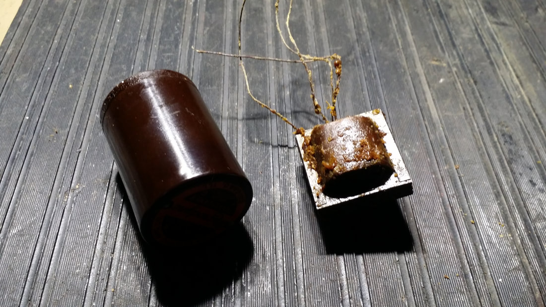
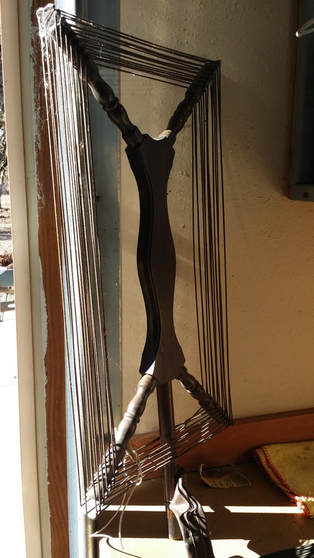
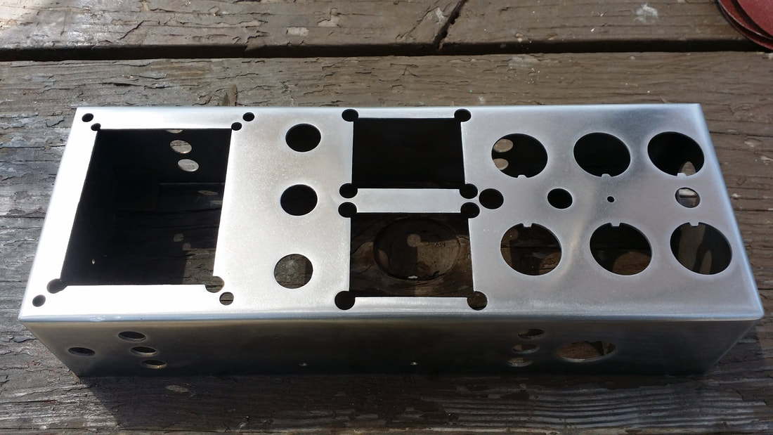
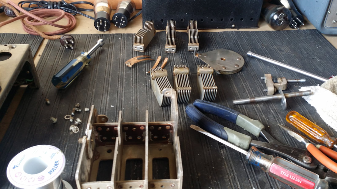
Above, left to right: Spider, Voice coil and the new cone assembly
Now - or sometime - run down to WalMart and get a folder of black greeting card material from the craft department (about $6). It will have many 12" X 12" sheets of card material that is nearly perfect for early speaker cones. In the same department find a yard of black canvas material (about $4). Make sure that the canvas is cloth, not plastic that looks like canvas. If you can't find black, you can dye or paint other colors (if paint is used, go lightly with black lacquer NOT enamel, which can become ridged). The material should be about the thickness/flexible as your jeans (real jeans not "stretchy" jeans). You might even be able to make the surround out of old jeans.
Now - or sometime - run down to WalMart and get a folder of black greeting card material from the craft department (about $6). It will have many 12" X 12" sheets of card material that is nearly perfect for early speaker cones. In the same department find a yard of black canvas material (about $4). Make sure that the canvas is cloth, not plastic that looks like canvas. If you can't find black, you can dye or paint other colors (if paint is used, go lightly with black lacquer NOT enamel, which can become ridged). The material should be about the thickness/flexible as your jeans (real jeans not "stretchy" jeans). You might even be able to make the surround out of old jeans.
Lay the old paper cone on top of the new card-paper and draw around the edge. If pieces are missing from the original cone you are going to have to extrapolate the missing circumference from what you have. This can be done simply by rotating the piece that you have around a FIXED center. For this it may be easier to tape the old cone to the new paper and locate the center of the circle and MARK it. This might take some 8th grade geometry and a compass, but you can do it with out the compass. Hint: use the radius - 1/2 the diameter - and make arcs in the center with one leg of the compass - stick - ruler fixed on the outer edge. Three or more arcs will intersect at the center of the circle..
You can lay the metal spider on the marked center and draw around the circumference. Then make a mark about 3/16" inside of the spider circumference since this material must be captured between the spider and the voice coil. Make another circle and cut it out.
The pie-shaped chunk that must be removed so a cone can be formed should be guesstimated from the original. Keep in mind the edges of the cut need to overlap about 1/4 inch so they can be glued.
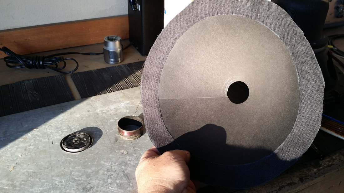
Now cut the new suspension from the canvas. You can cut out 3 pieces like the original had or just use one. If you use 3 pieces they must overlap about 1/4 of an inch and be glued together to form a ring. These attachment areas can become stiff especially if too much glue is used, so one piece is a lot easier.
You can use a piece of the old surround or the outer lip of the basket to draw a circle on the canvas. If the basket is used, when you make your cut remember that the material will fit inside of the lip so the cut should be made about 1/8" inside of the mark. You will now have a circle of canvas about 11" in diameter.
Use your compass - ruler - stick - whatever, to mark the inside edge of the material. Finding the center as described above might be useful. Use a piece of the old surround material to check the width of this material. There must be enough to reach the outer lip of the basket and have enough to overlap the new cone about 1/4 of an inch. When you are done you should have a ring. The outer edge will not be visible but attention to the inner edge will pay off since it is visible and uneven cuts will look bad.
You can lay the metal spider on the marked center and draw around the circumference. Then make a mark about 3/16" inside of the spider circumference since this material must be captured between the spider and the voice coil. Make another circle and cut it out.
The pie-shaped chunk that must be removed so a cone can be formed should be guesstimated from the original. Keep in mind the edges of the cut need to overlap about 1/4 inch so they can be glued.
Now cut the new suspension from the canvas. You can cut out 3 pieces like the original had or just use one. If you use 3 pieces they must overlap about 1/4 of an inch and be glued together to form a ring. These attachment areas can become stiff especially if too much glue is used, so one piece is a lot easier.
You can use a piece of the old surround or the outer lip of the basket to draw a circle on the canvas. If the basket is used, when you make your cut remember that the material will fit inside of the lip so the cut should be made about 1/8" inside of the mark. You will now have a circle of canvas about 11" in diameter.
Use your compass - ruler - stick - whatever, to mark the inside edge of the material. Finding the center as described above might be useful. Use a piece of the old surround material to check the width of this material. There must be enough to reach the outer lip of the basket and have enough to overlap the new cone about 1/4 of an inch. When you are done you should have a ring. The outer edge will not be visible but attention to the inner edge will pay off since it is visible and uneven cuts will look bad.
Glue the edges of the pie-shaped cut-out together forming a cone with the center missing (cut-out for spider/VC)
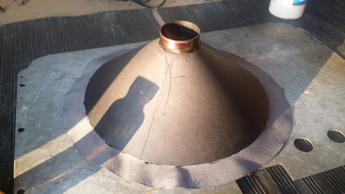
Lay your new cone on top of the new surround material. Check that there is about 1/4 inch of material overlapping the paper ALL THE WAY AROUND the outer edge of the cone. Use a small paint-brush to spread yellow wood glue on the outer edge of the paper cone and the inner edge of the cloth surround. You can use a contact cement but I have found cones attached using it will fall apart later. Let the assembly dry for about 1/2 hr. If the overlap of the material is uneven it will be difficult to center the cone assembly, so take care.
Now the cone is set on top of the voice coil former (tube) and the spider is pressed into the former capturing the inner edge of the cone between them. Like with the surround, care must be taken to center the components or the cone will be impossible to align and the VC will rub on the pole piece (center of the magnet structure). Make sure that you are attaching the cone to the proper end of the VC former since the voice coil is closer to one end and an error will move it out of the magnetic gap. This is usually a tight fit - be careful not to damage the cone. A little bit of glue will both lubricate the spider/cone/VC connection for assembly and secure the finished product.
Allow the glue to dry for a few minutes.
Put the cone assembly back inside of the speaker basket sliding the voice coil into the magnetic gap around the pole piece. The 2 wires leading to the voice coil should end up at the correct place in the basket which is CLOSEST to the original atachemet points. Not observing this precaution will make hooking up th VC wires correctly - impossible.
At this point the surround should be sitting near the correct position around the circumference of the basket.
The next step is critical - The object is to align the cone/VC so that it does not rub on the pole piece or magnet structure.
This is sort of a three-handed maneuver so before you start, grow another hand or, possibly, ask for help (only required on the first attempt).
What I do is to put the screw back into the center of the spider, screwing it to the pole BUT leave it loose enough to move the spider around. By this point you will be able to estimate the quality of the rebuild by observing the fit of the VC inside of the magnetic gap. It should be loose and free to move BUT it may still rub.
Now, if everything is symmetrical the surround should be laying evenly inside of the outer lip of the basket. Using your soldering iron, Holes for the screws can be punched/burned through the canvas surround. Or you can use a blade or punch but I have found the hot iron easier. The three metal clamps are lined up over the surround capturing it between them and the basket. With the screw holes burnt/cut attach the 3 pieces but leave the screws loose so that the surround can be adjusted slightly.
Placing slight pressure on the inner cone area/spider will allow you to observe the fit of the VC inside of the gap. IT MUST NOT RUB on the pole or the magnet structure. Assuming that the VC former has not been damaged/bent and that the VC wire is still bound to it, slide the spider around on the center screw until the coil is centered in the gap - no longer rubs. Tighten the screw.
If you are having trouble centering the VC slight adjustment of the surround can be made but not enough adjustment can be made to compensate for a cone that is not symmetrical. Glue can be applied around the edge of the basket to secure the surround but this will make further adjustment impossible. Tightening the screws holding the 3 metal clamps is usually enough to secure the cone.
Reconnect (solder) the VC leads to the attachment points. Use your ohm meter to check the continuity of the VC.
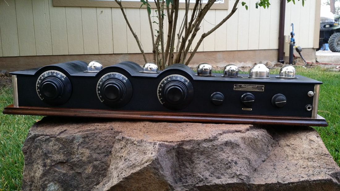
The speaker is ready to test.
Put the cone assembly back inside of the speaker basket sliding the voice coil into the magnetic gap around the pole piece. The 2 wires leading to the voice coil should end up at the correct place in the basket which is CLOSEST to the original atachemet points. Not observing this precaution will make hooking up th VC wires correctly - impossible.
At this point the surround should be sitting near the correct position around the circumference of the basket.
The next step is critical - The object is to align the cone/VC so that it does not rub on the pole piece or magnet structure.
This is sort of a three-handed maneuver so before you start, grow another hand or, possibly, ask for help (only required on the first attempt).
What I do is to put the screw back into the center of the spider, screwing it to the pole BUT leave it loose enough to move the spider around. By this point you will be able to estimate the quality of the rebuild by observing the fit of the VC inside of the magnetic gap. It should be loose and free to move BUT it may still rub.
Now, if everything is symmetrical the surround should be laying evenly inside of the outer lip of the basket. Using your soldering iron, Holes for the screws can be punched/burned through the canvas surround. Or you can use a blade or punch but I have found the hot iron easier. The three metal clamps are lined up over the surround capturing it between them and the basket. With the screw holes burnt/cut attach the 3 pieces but leave the screws loose so that the surround can be adjusted slightly.
Placing slight pressure on the inner cone area/spider will allow you to observe the fit of the VC inside of the gap. IT MUST NOT RUB on the pole or the magnet structure. Assuming that the VC former has not been damaged/bent and that the VC wire is still bound to it, slide the spider around on the center screw until the coil is centered in the gap - no longer rubs. Tighten the screw.
If you are having trouble centering the VC slight adjustment of the surround can be made but not enough adjustment can be made to compensate for a cone that is not symmetrical. Glue can be applied around the edge of the basket to secure the surround but this will make further adjustment impossible. Tightening the screws holding the 3 metal clamps is usually enough to secure the cone.
Reconnect (solder) the VC leads to the attachment points. Use your ohm meter to check the continuity of the VC.
The speaker is ready to test.


 RSS Feed