
Sorry it has been so long since I posted. Honestly, if the smoke from the forest fires was not so thick outside, right now, I would probably be on my way to the shop.
About two months ago we were given a large collection of radios, chassis and parts. This was such a nice thing to do. The collector had just retired. He had a lot of projects and travel planned and did not want to liquidate the collection by selling individual radios.
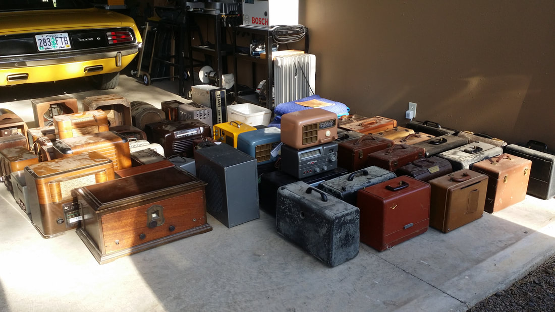
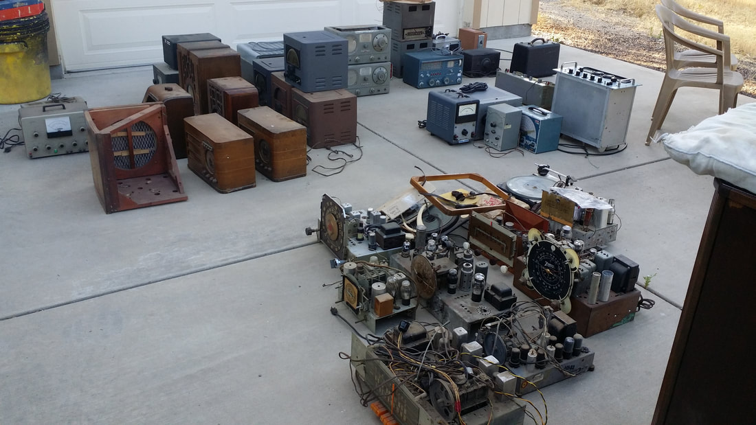
So after two truck/trailer loads, there were radios stacked in the shop and at both the front and back doors.
About two months ago we were given a large collection of radios, chassis and parts. This was such a nice thing to do. The collector had just retired. He had a lot of projects and travel planned and did not want to liquidate the collection by selling individual radios.
So after two truck/trailer loads, there were radios stacked in the shop and at both the front and back doors.
Well, I may be a radio collector (hoarder), but I am also unable to allow stuff to pile up for very long. So for the past two months I have been cleaning, restoring, donating, selling and disposing of this collection. But, that is not what this post is about. The rest of that story will be posted later.
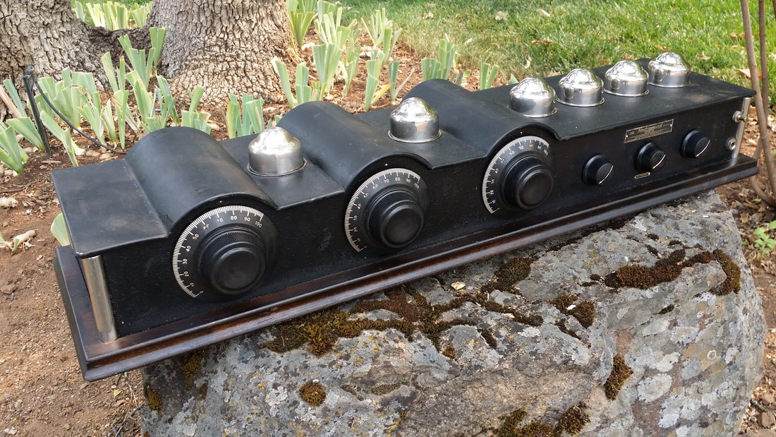
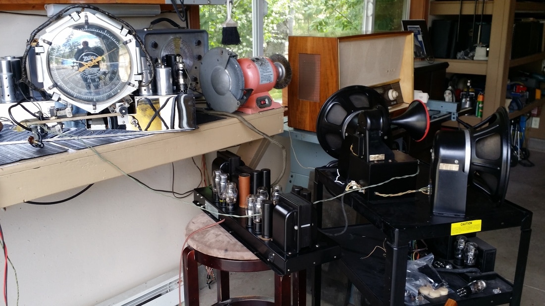
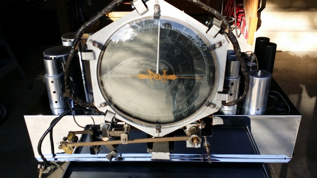
THIS story is about the two 1926 Neutrowound receivers that I acquired in the meantime.
THIS story is about the two 1926 Neutrowound receivers that I acquired in the meantime.
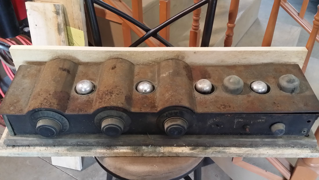
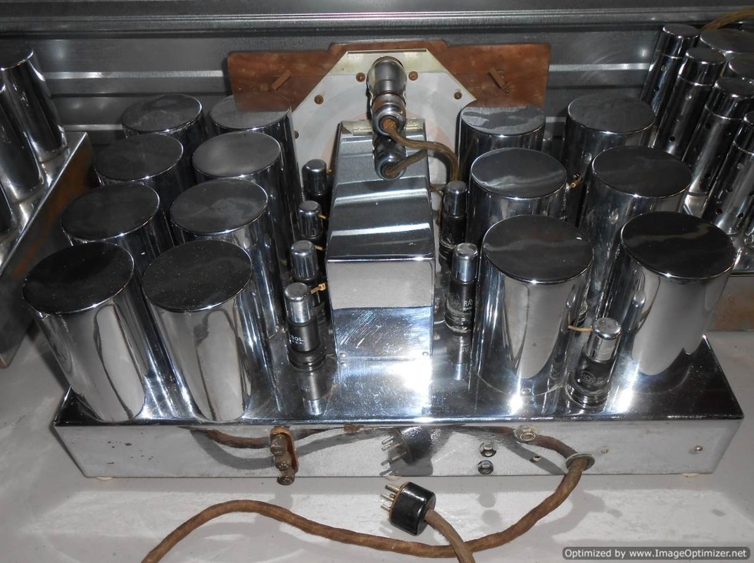
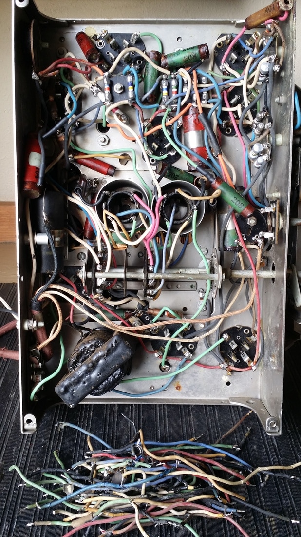
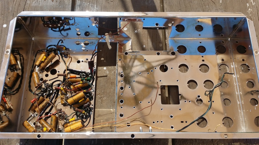
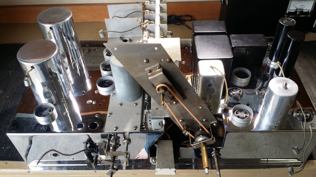
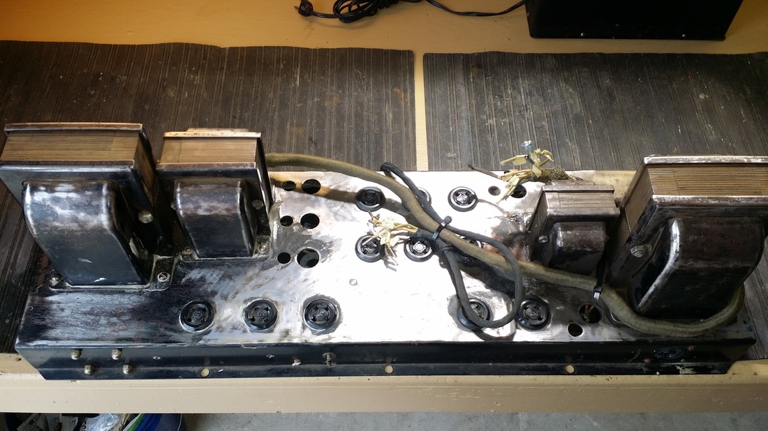
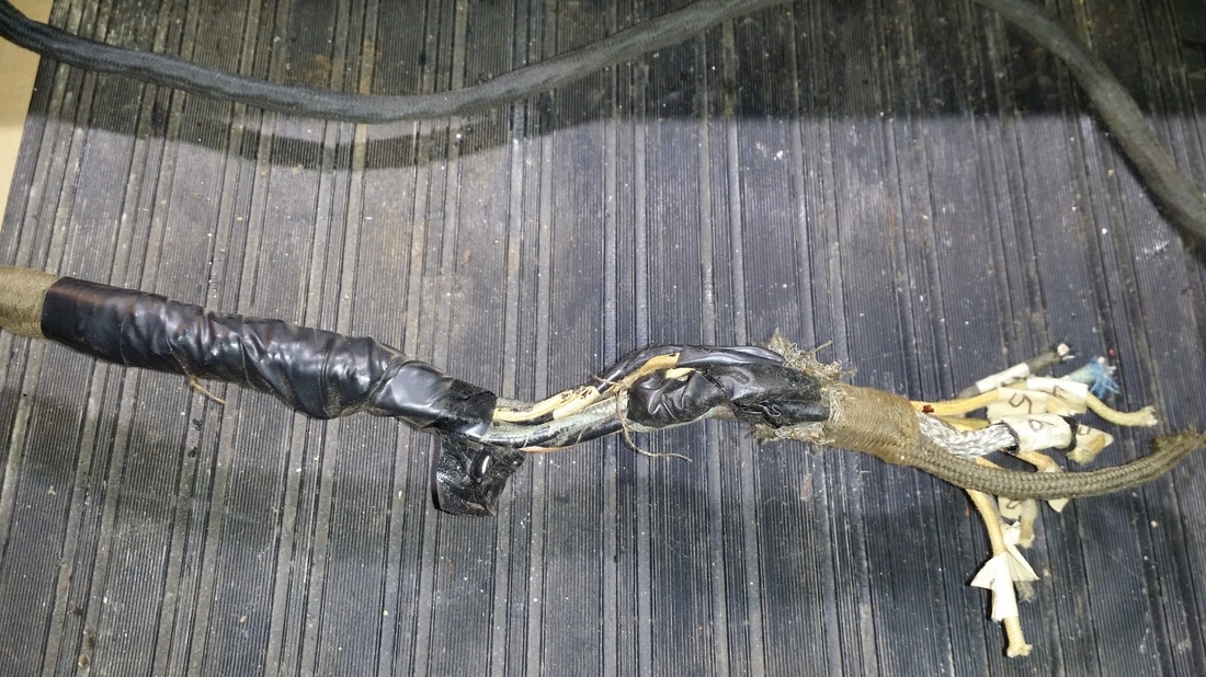
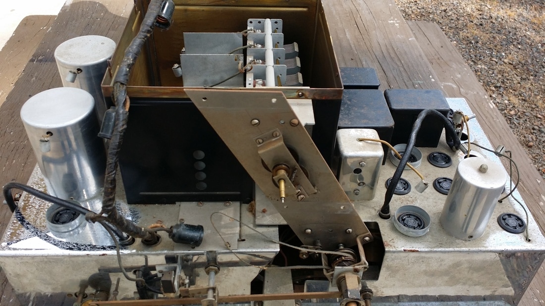
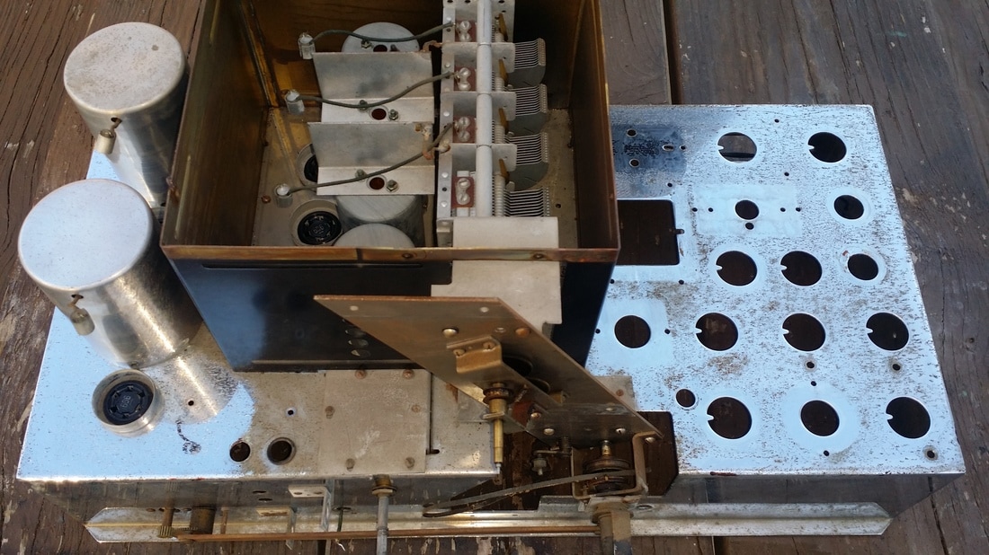
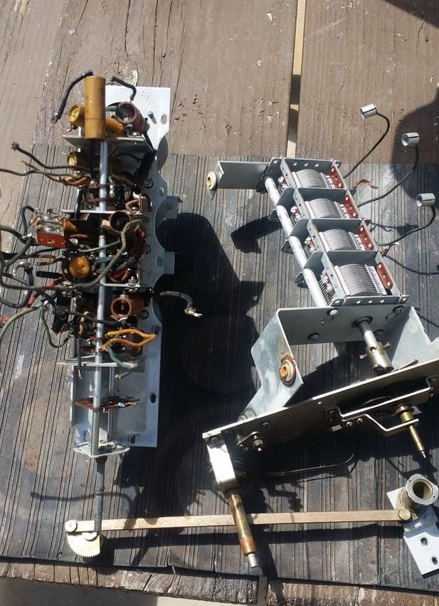
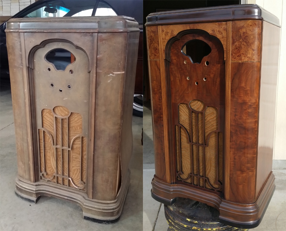
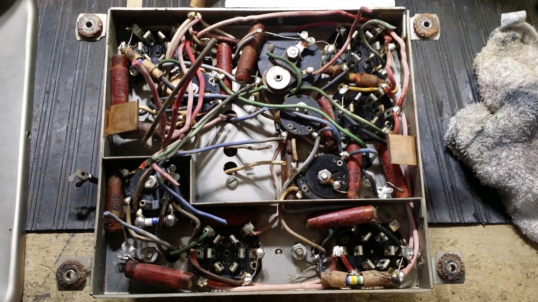
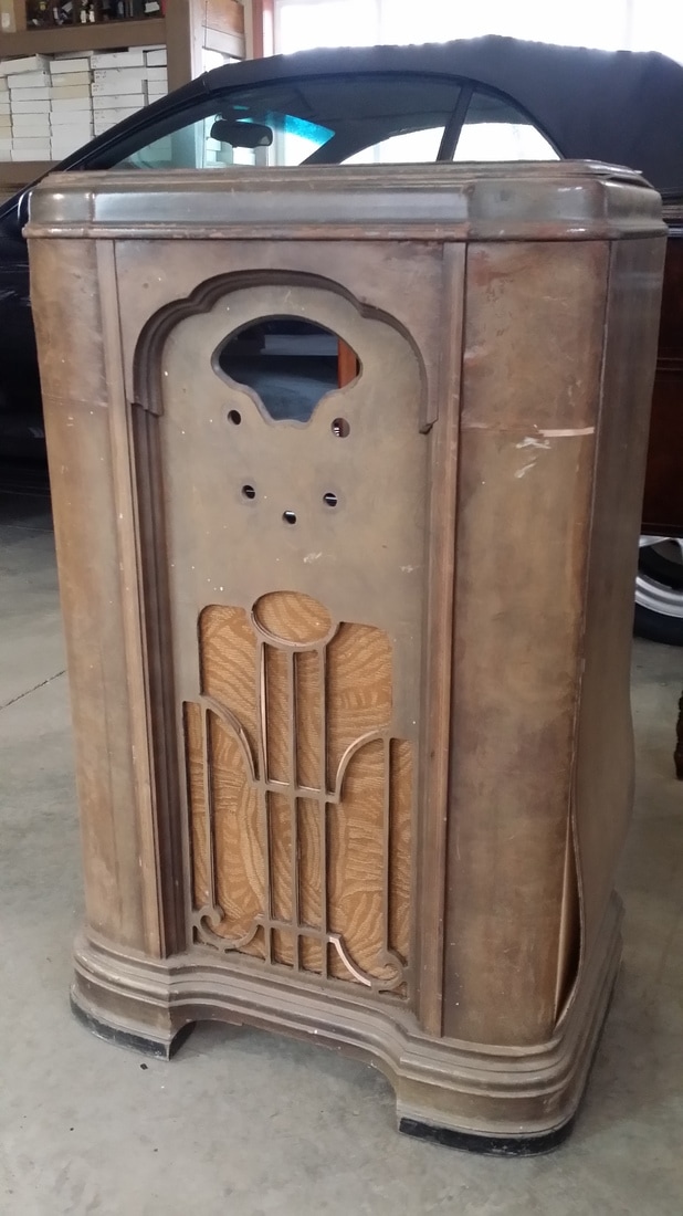
Of the two, the one pictured above, was by far in the worst condition. Even though it was well packed, it arrived soaking wet. That probably did not account for the rust and bug nests, but it didn't help either. BTW, none of those tubes were good either. All of them had open filaments.
I am in the process of saving the specimen above. The greatest challenge will be finding the missing tube shields/covers.
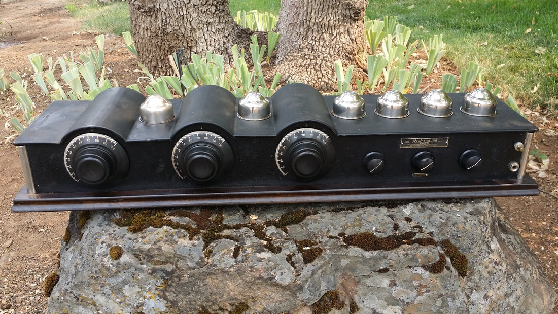
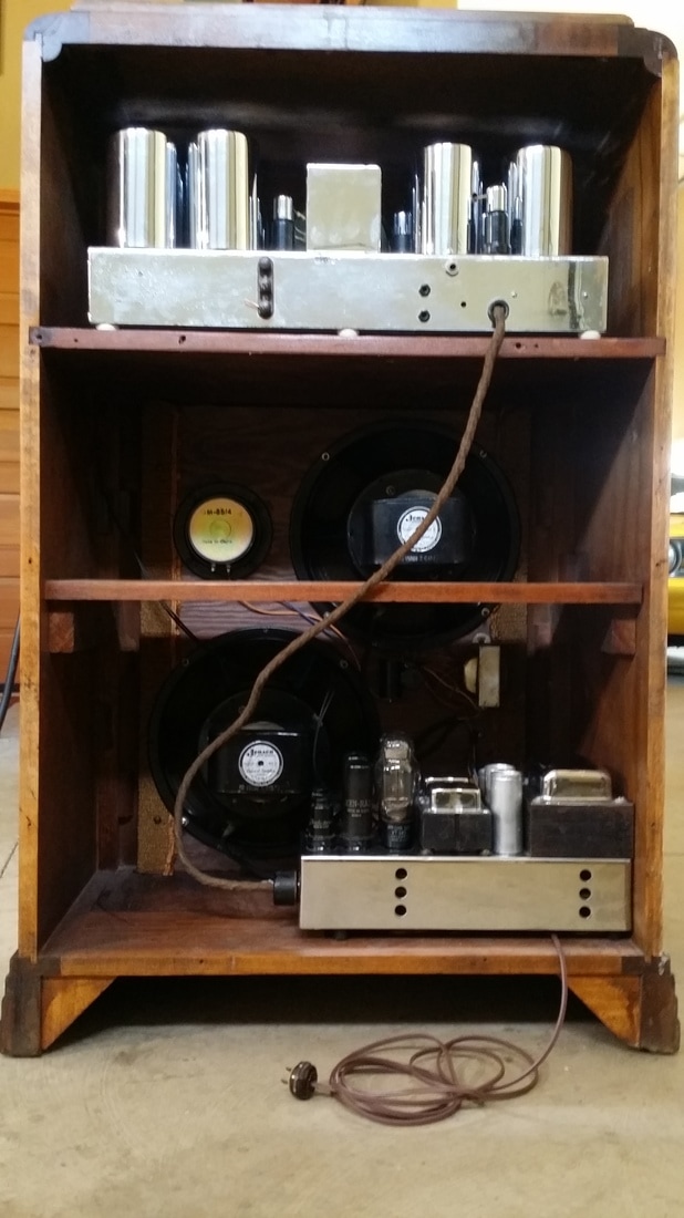
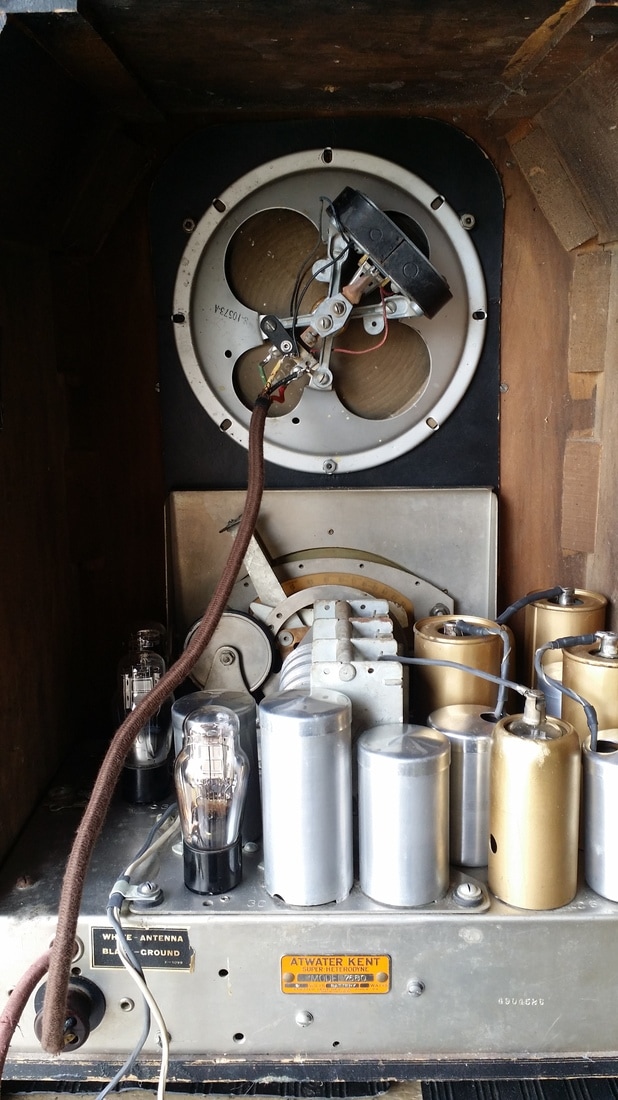
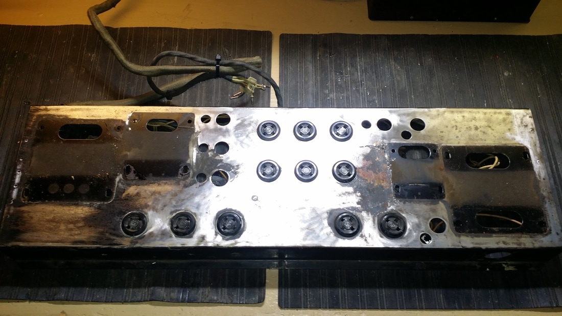
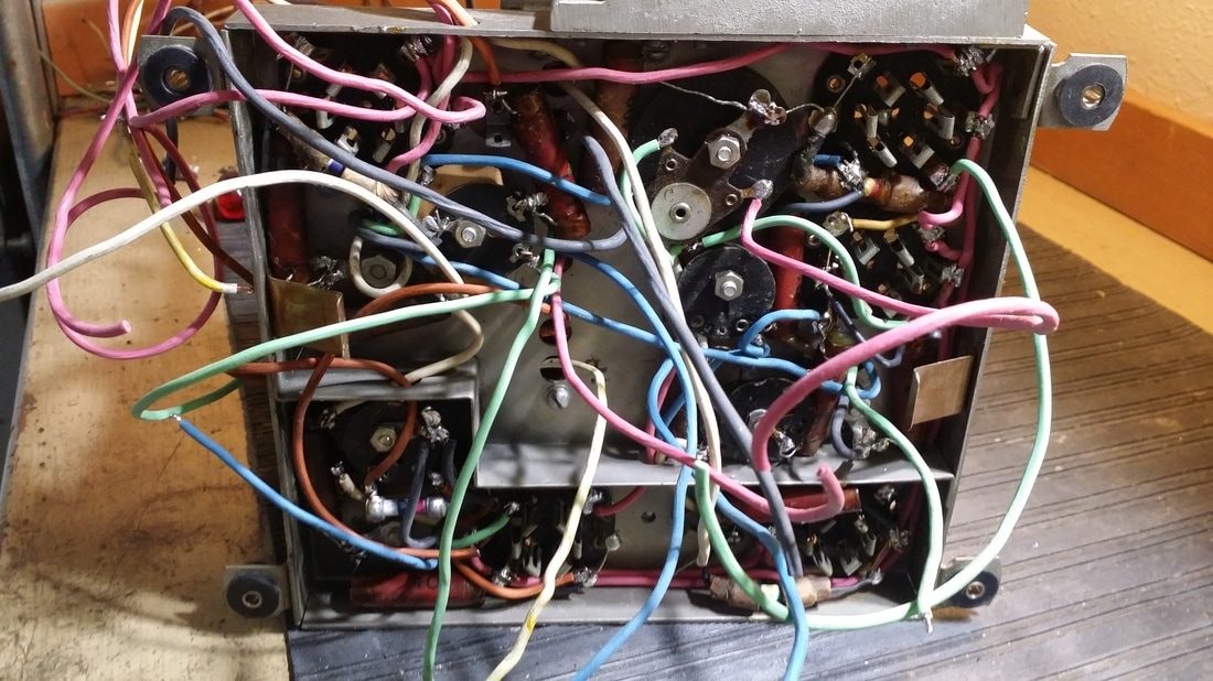
For the moment, we'll concentrate on the other unit, below.
I am in the process of saving the specimen above. The greatest challenge will be finding the missing tube shields/covers.
For the moment, we'll concentrate on the other unit, below.
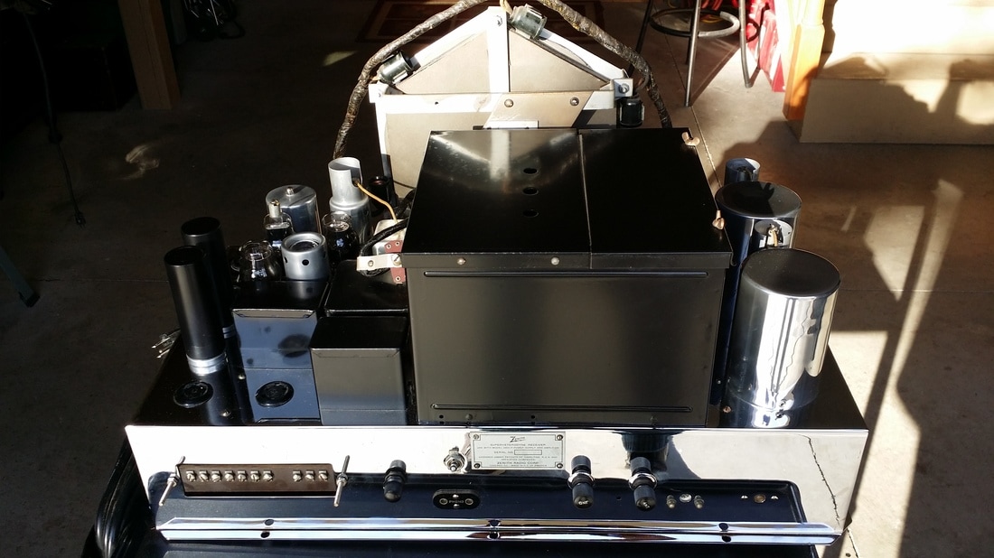
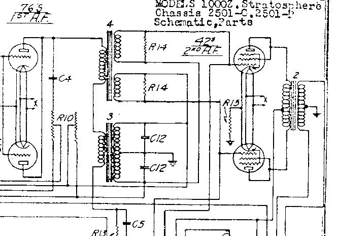
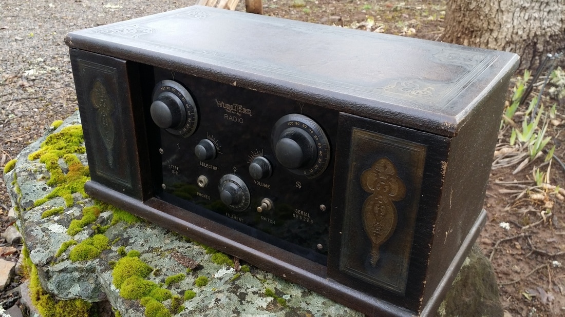
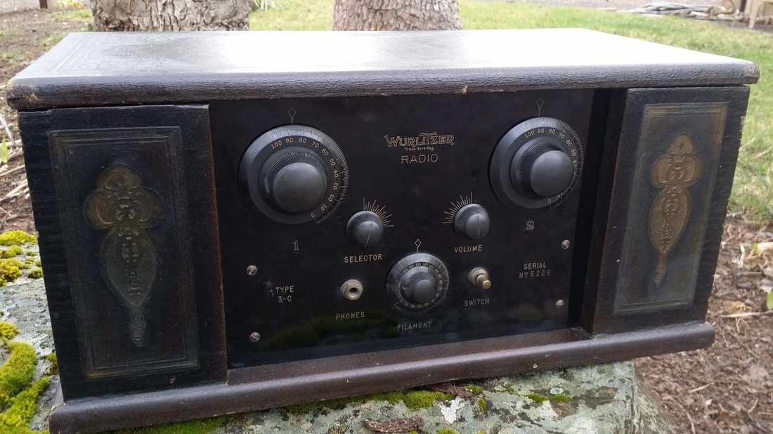
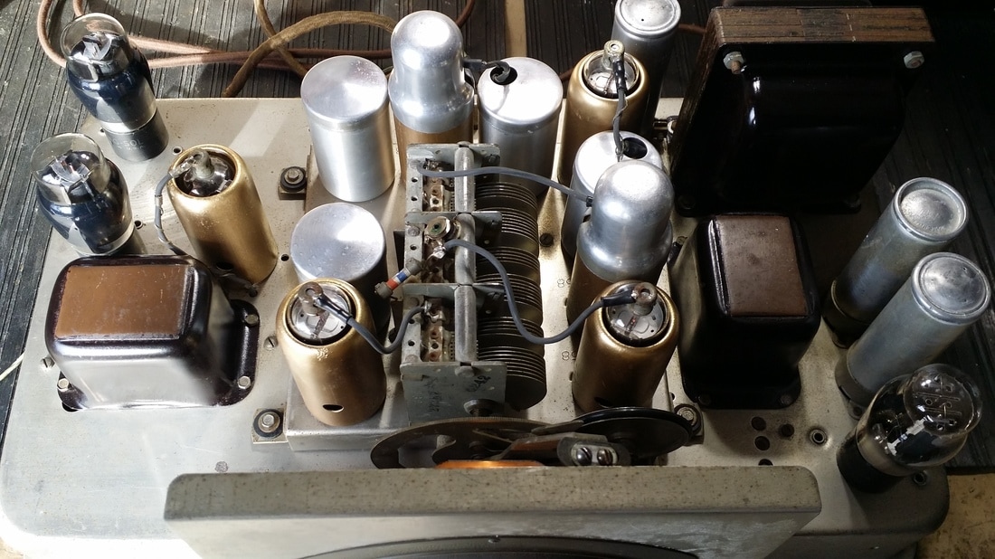
I won't take the time to illustrate the history of Neutrowound Radio Manuf. except to say that this division of Advanced Automotive Accessories only made radios for 4 or 5 years. This "Shielded Breadboard" design carried through those years with a few modifications.
Though this is a good radio, by 1926 the design was a bit dated. Then by 1928, the battery powered TRF was really behind the times. I can't really see why this design was popular in any of the years it was produced.
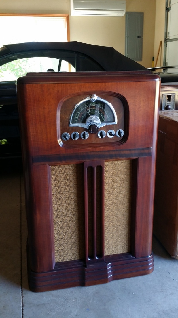
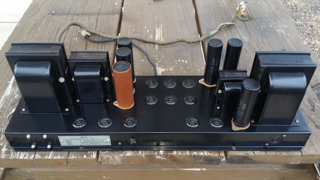
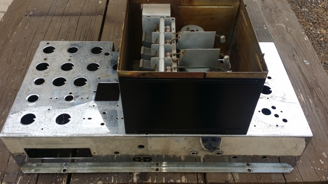
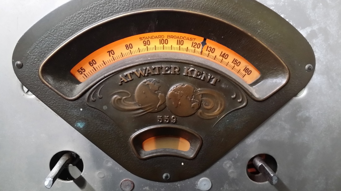
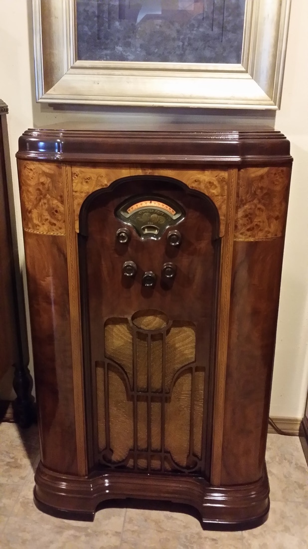
Pictures really don't express the size of this radio, measuring almost 3 feet long. It had 3 stages of tuning and the 3 dials rather than a single dial, as was becoming the standard of the time. I suppose that in a home that was yet to be "electrified" the need for batteries in 1927/28 was not a problem but elsewhere, the new AC powered radios were more desirable
.
Though this is a good radio, by 1926 the design was a bit dated. Then by 1928, the battery powered TRF was really behind the times. I can't really see why this design was popular in any of the years it was produced.
Pictures really don't express the size of this radio, measuring almost 3 feet long. It had 3 stages of tuning and the 3 dials rather than a single dial, as was becoming the standard of the time. I suppose that in a home that was yet to be "electrified" the need for batteries in 1927/28 was not a problem but elsewhere, the new AC powered radios were more desirable
.
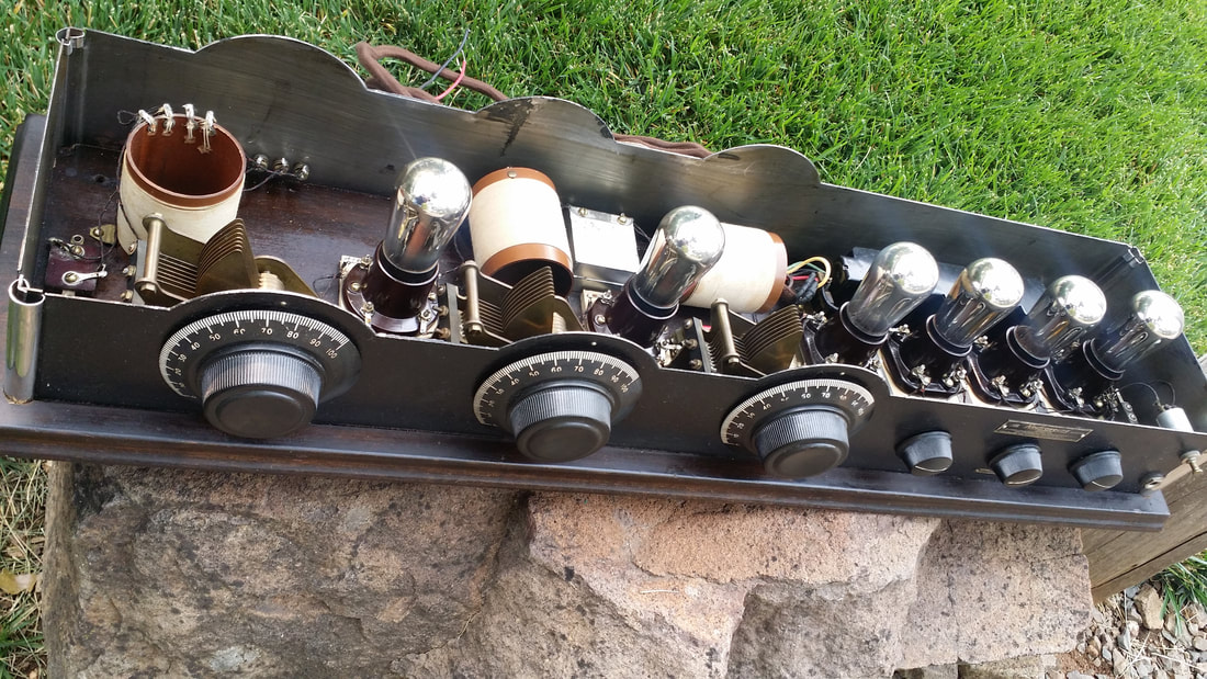
Radio construction on a "breadboard" was quickly becoming a thing of the past.
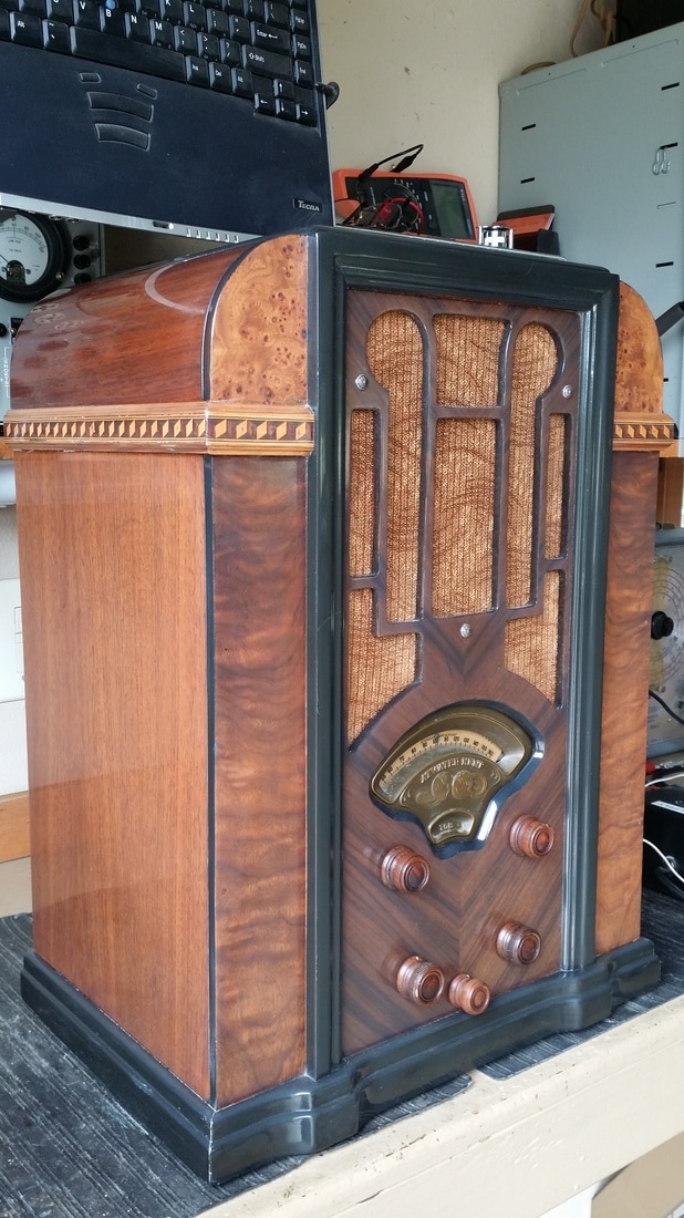
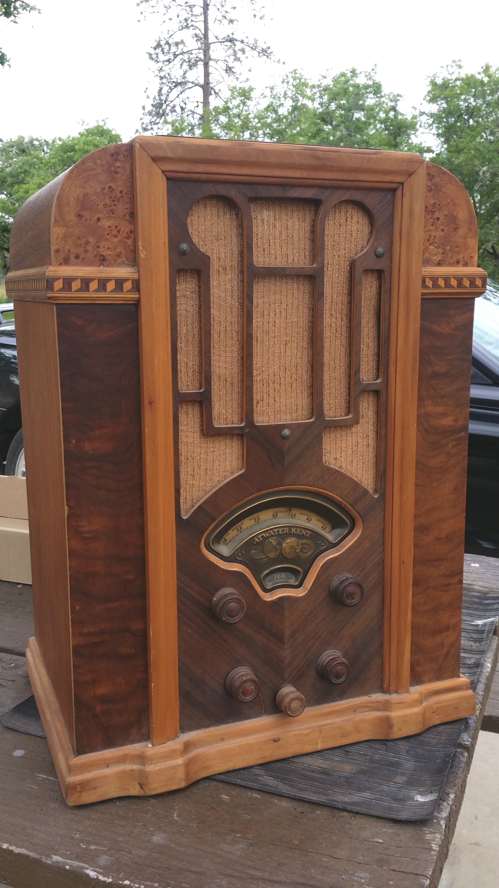
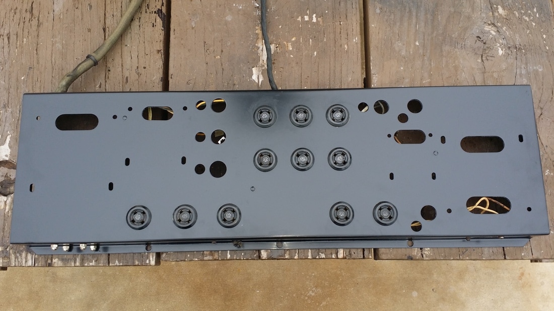
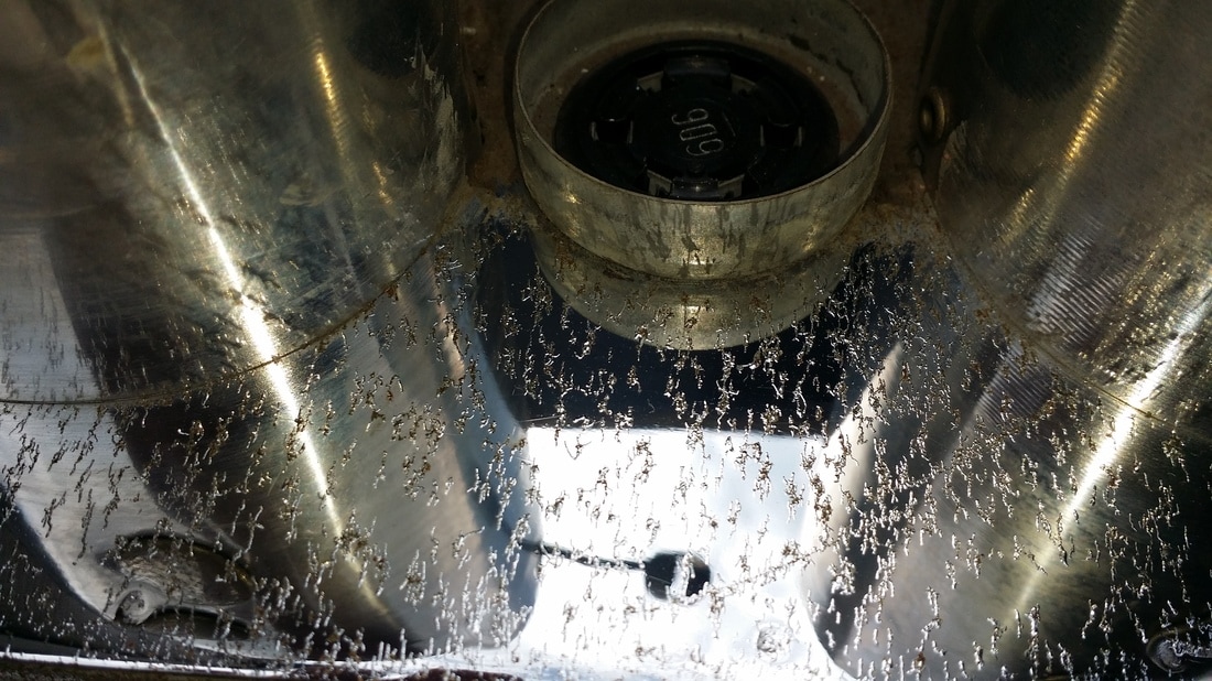
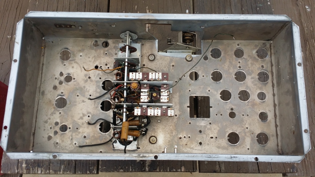
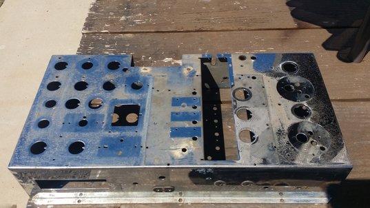
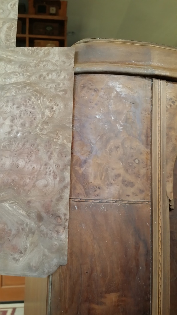
There are two significant and nearly universal challenges to restoring any of these radios. The first is RUST. A crinkle coat paint was applied to the outer metal surfaces. In the 1927 models this could be a striking blue or red. In all of the models, adhesion - at least in the long term, was not so good. This lead to a lot of rusted cabinets (see top pictures). Coupled to that, it seems that in the finishing process, shellac was applied (smeared) to the inner surfaces of the metal. This hit or miss finish led to rust on the inner surfaces as well.
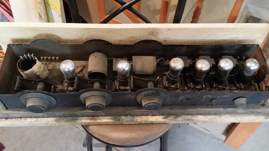
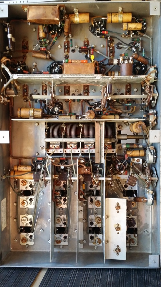
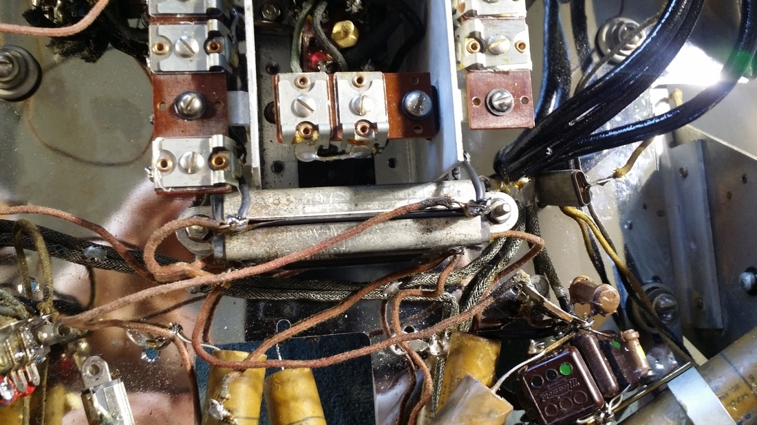
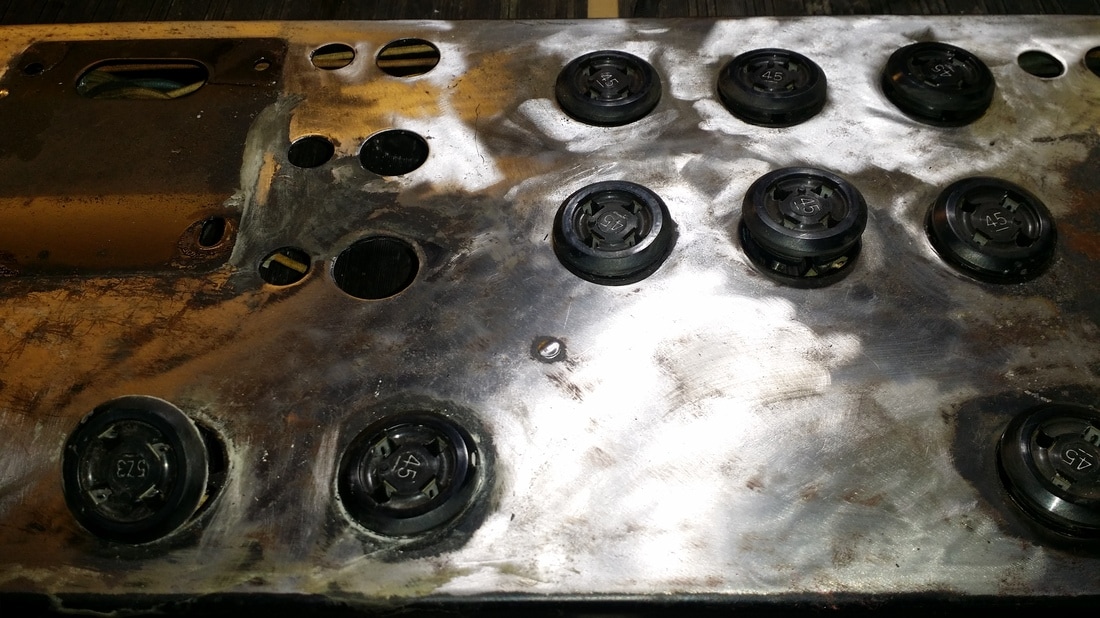
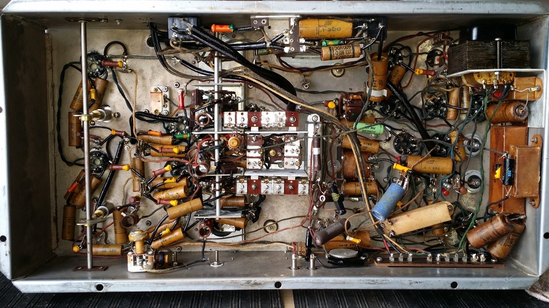
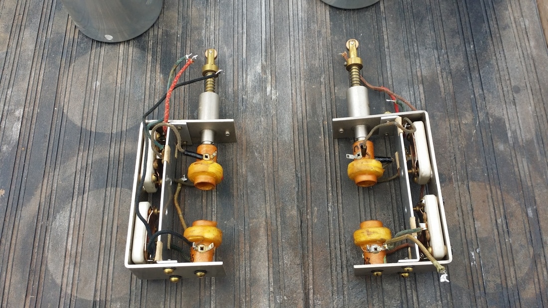
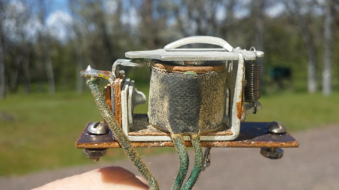
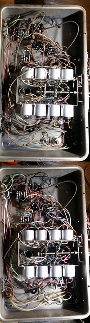
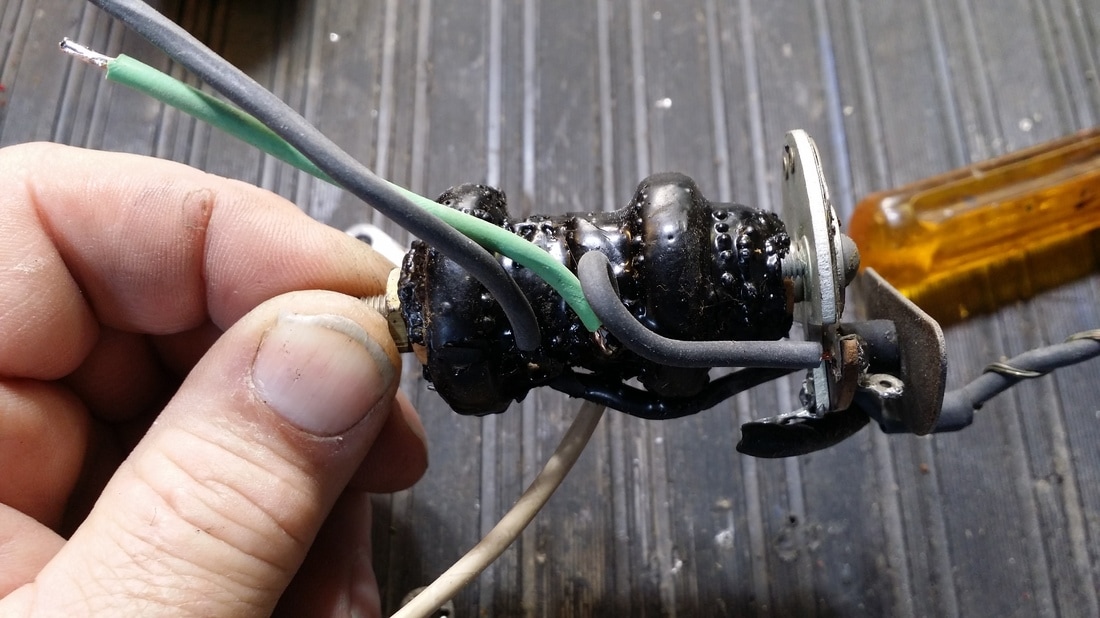
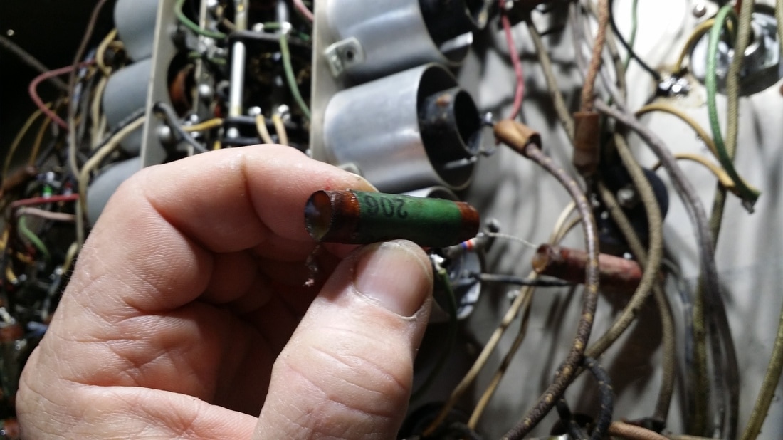
The second and probably most encompassing issue is caused by the degradation of the gum-rubber mounting of the Kellogg tube sockets.
There are two significant and nearly universal challenges to restoring any of these radios. The first is RUST. A crinkle coat paint was applied to the outer metal surfaces. In the 1927 models this could be a striking blue or red. In all of the models, adhesion - at least in the long term, was not so good. This lead to a lot of rusted cabinets (see top pictures). Coupled to that, it seems that in the finishing process, shellac was applied (smeared) to the inner surfaces of the metal. This hit or miss finish led to rust on the inner surfaces as well.
The second and probably most encompassing issue is caused by the degradation of the gum-rubber mounting of the Kellogg tube sockets.
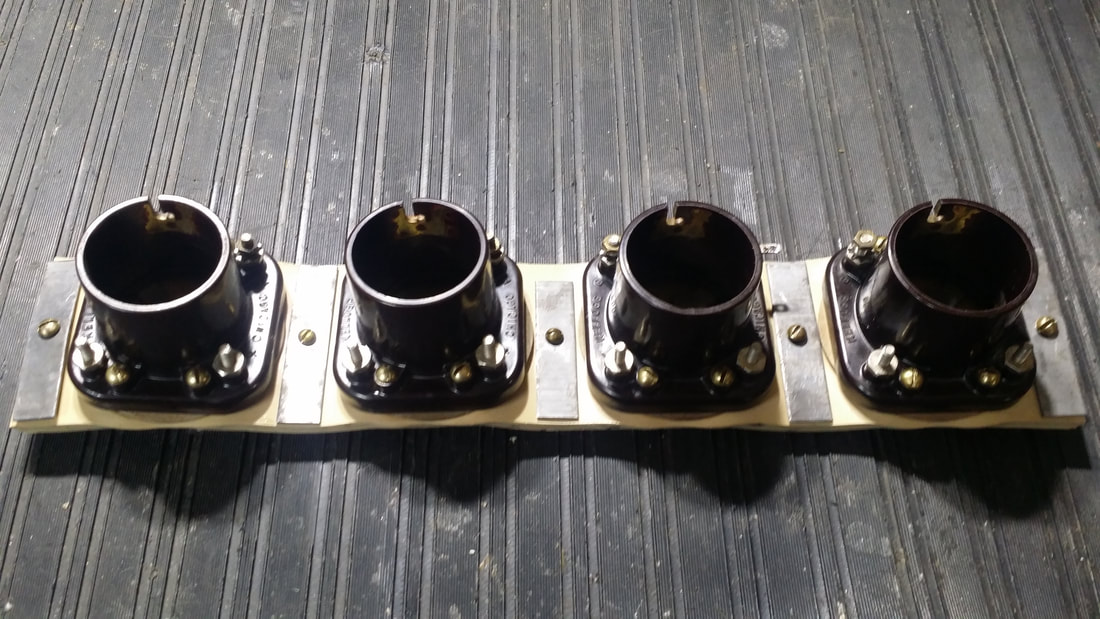
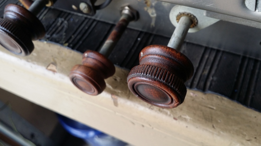
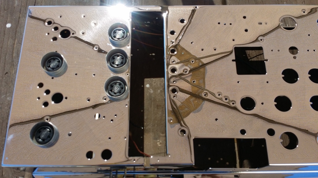
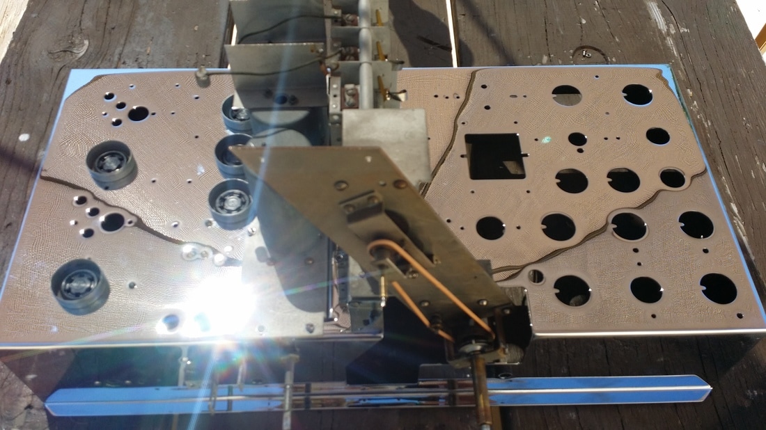
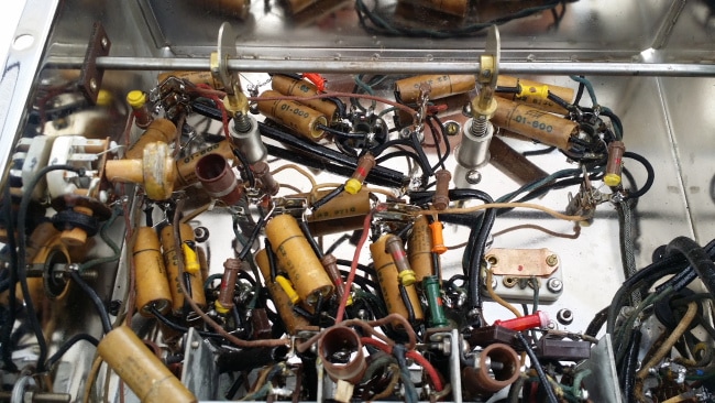
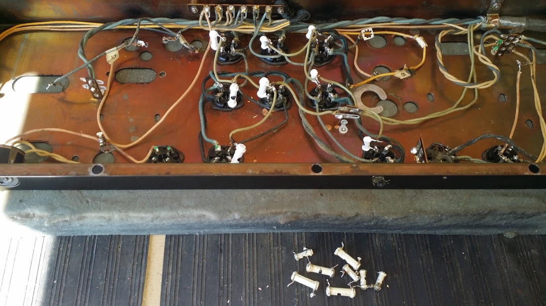
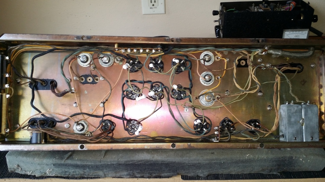
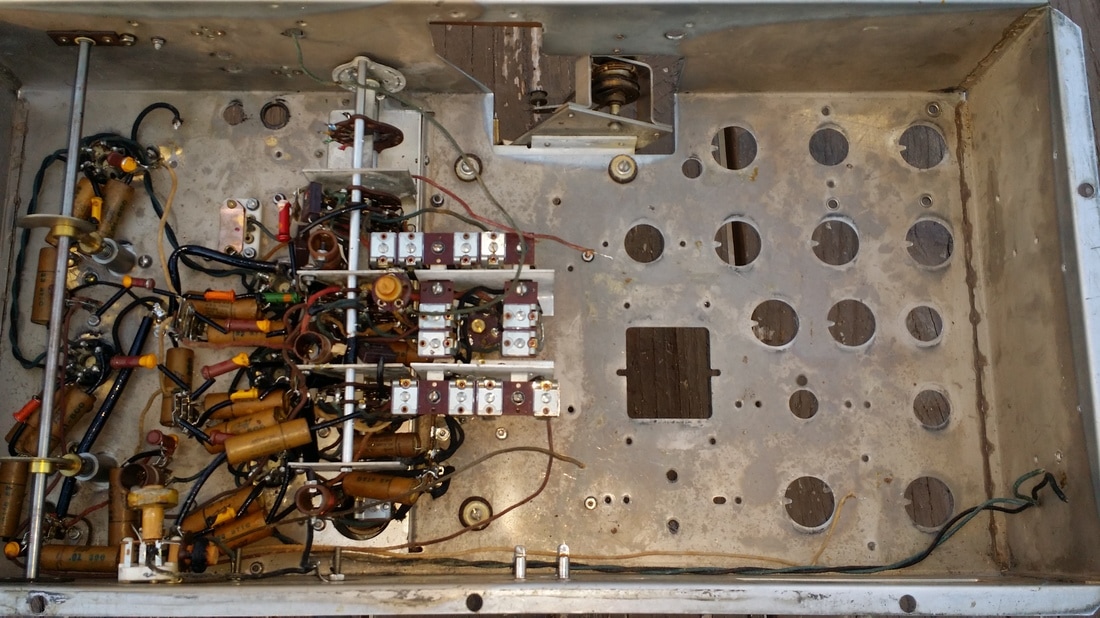
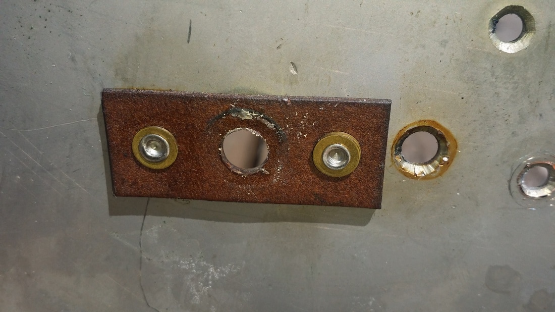
The first two tubes have somewhat of a "hard" mounting since the screws pass through the socket flanges, through the 1/4 inch gum-rubber and into the breadboard. The last 4 tube socket are fully floating on the rubber strip shown above having been replaced.
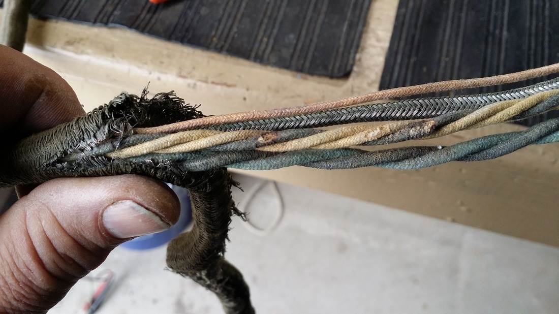
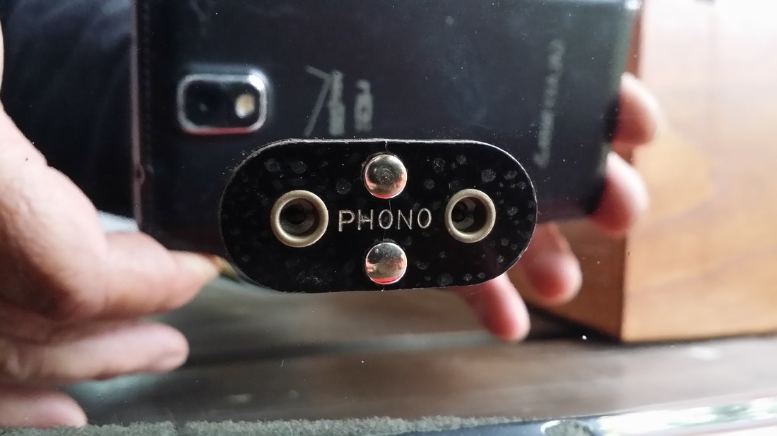
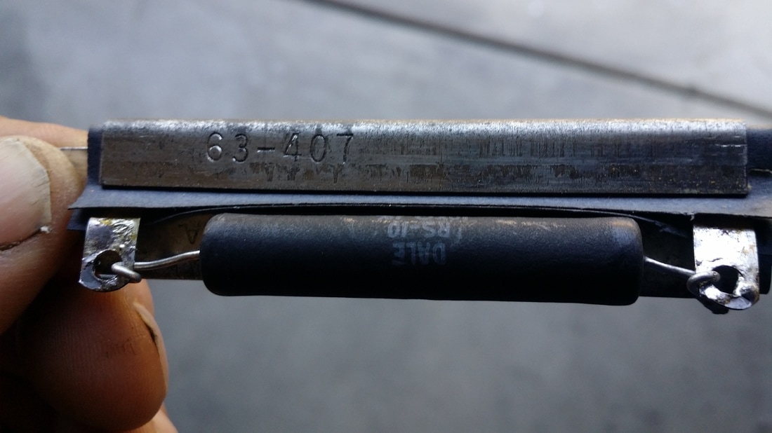
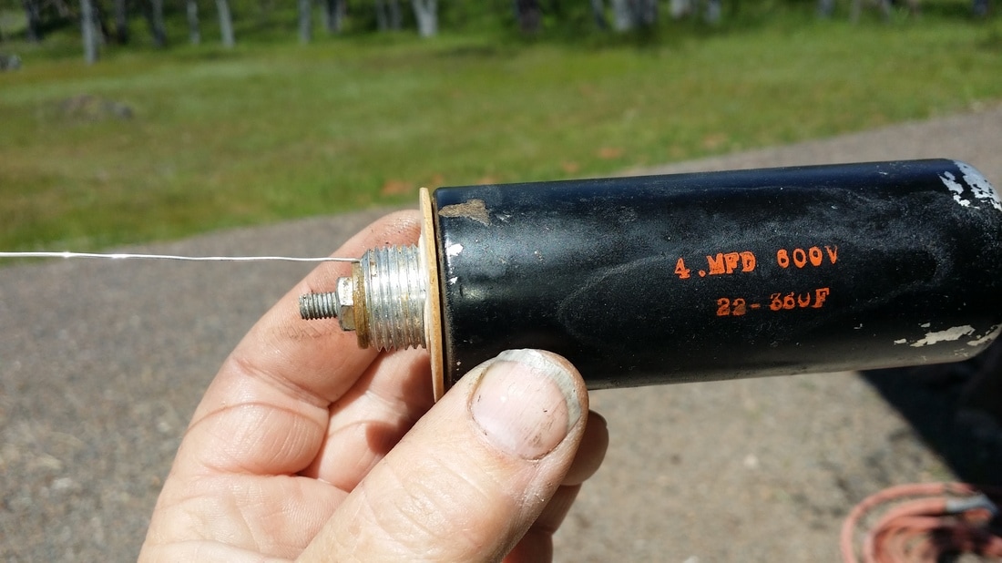
I have not seen an example of this radio where the rubber has not become powdered or at least the consistency of a sugar cookie. Needles to say, the rubber should be replaced. Gum-rubber sheet is not a common hardware item anymore and the cost of a piece may be significant. Mounting the sockets on new rubber is not an easy task either.
I have not seen an example of this radio where the rubber has not become powdered or at least the consistency of a sugar cookie. Needles to say, the rubber should be replaced. Gum-rubber sheet is not a common hardware item anymore and the cost of a piece may be significant. Mounting the sockets on new rubber is not an easy task either.
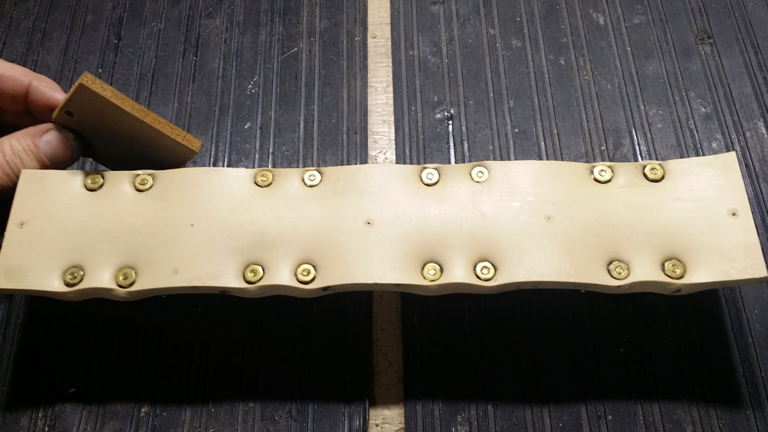
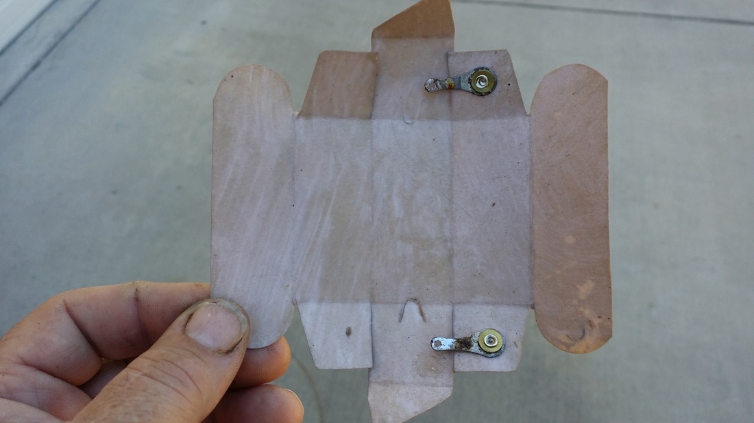
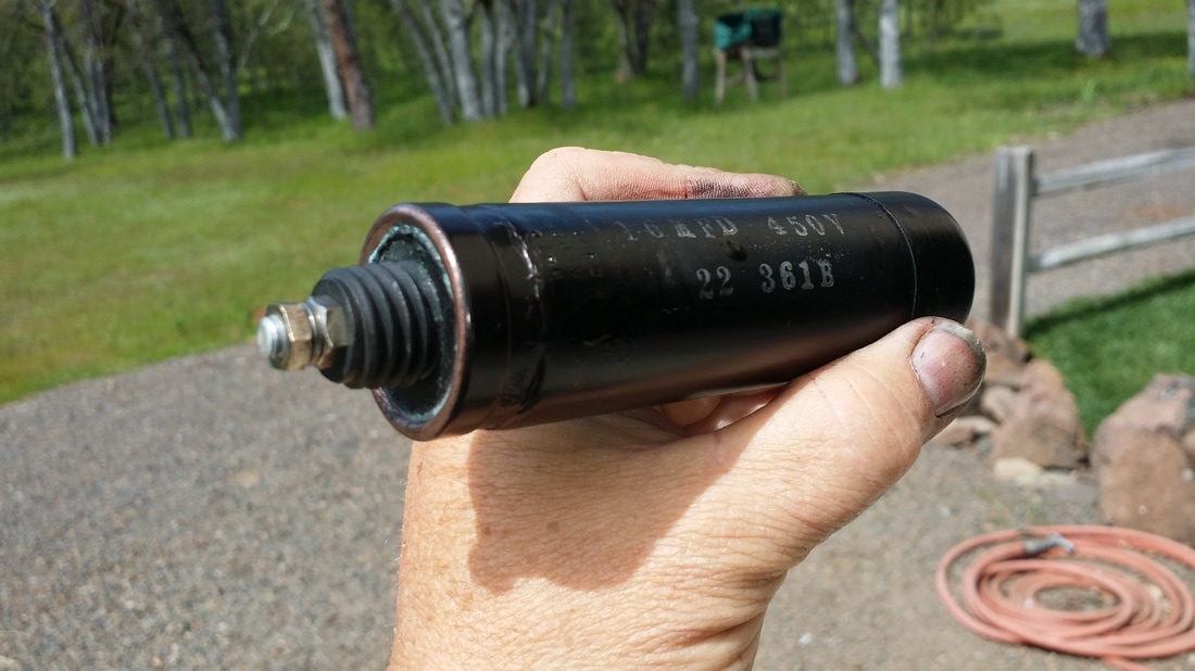
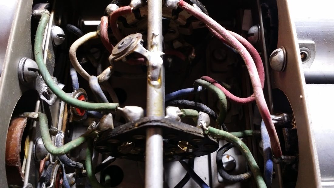
Above, I am holding an original piece of the rubber mount.
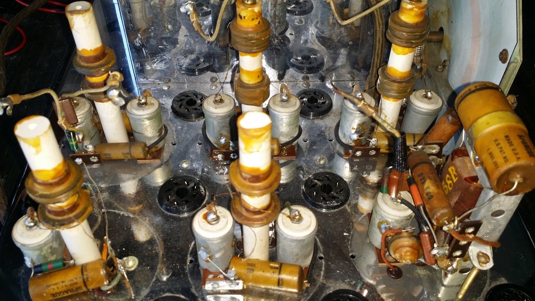
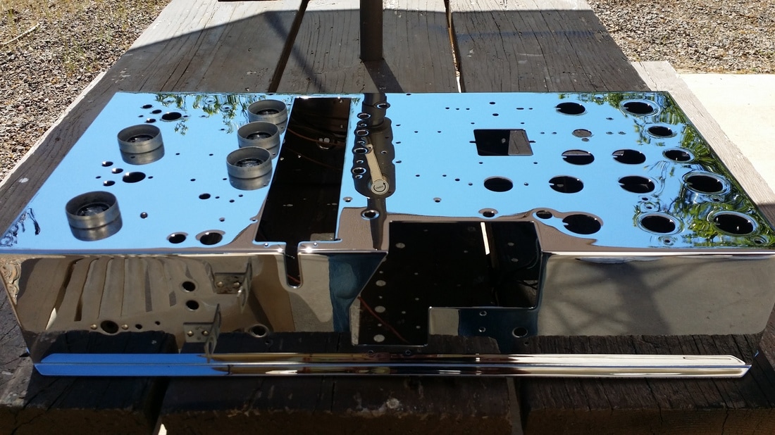
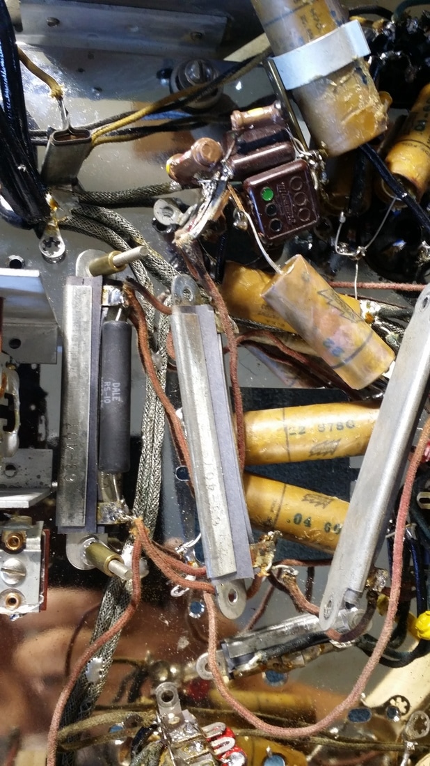
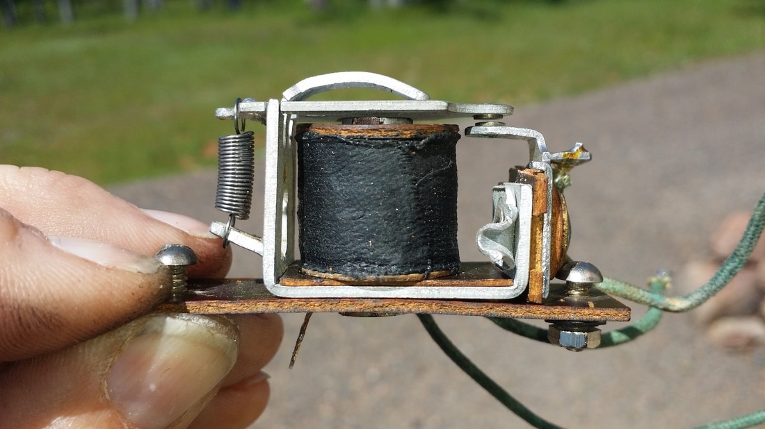
As you can see, mounting the sockets requires careful placement and compression of the rubber. This mount must compress the rubber without making a big hole in it, which would require starting over. I had to make a jig to hold the nuts/washers while compressing the assembly from the top. Otherwise, at least 3 (frustrated) hands would be required. By the time I made a few of these, the task was not so impossible, but at first it certainly seemed so.
Now consider what would happen if the sockets/tubes were not in the correct position. You probably would not notice until you tried to replace the top cover and even more so as you tried to install the shields. In other words, incorrect placement results in the tubes hitting the top cover and/or the shields. The best you could hope for in this situation would be for the rubber base to give enough to allow the tube to fit through the hole at a slant - not acceptable.
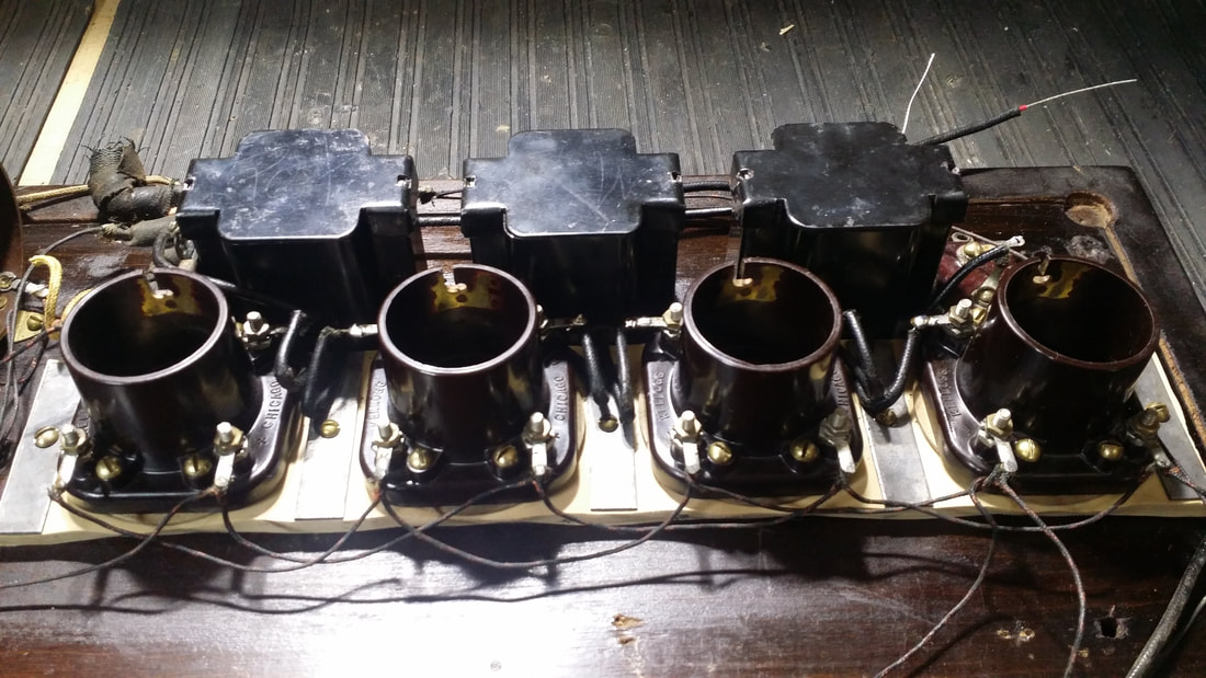
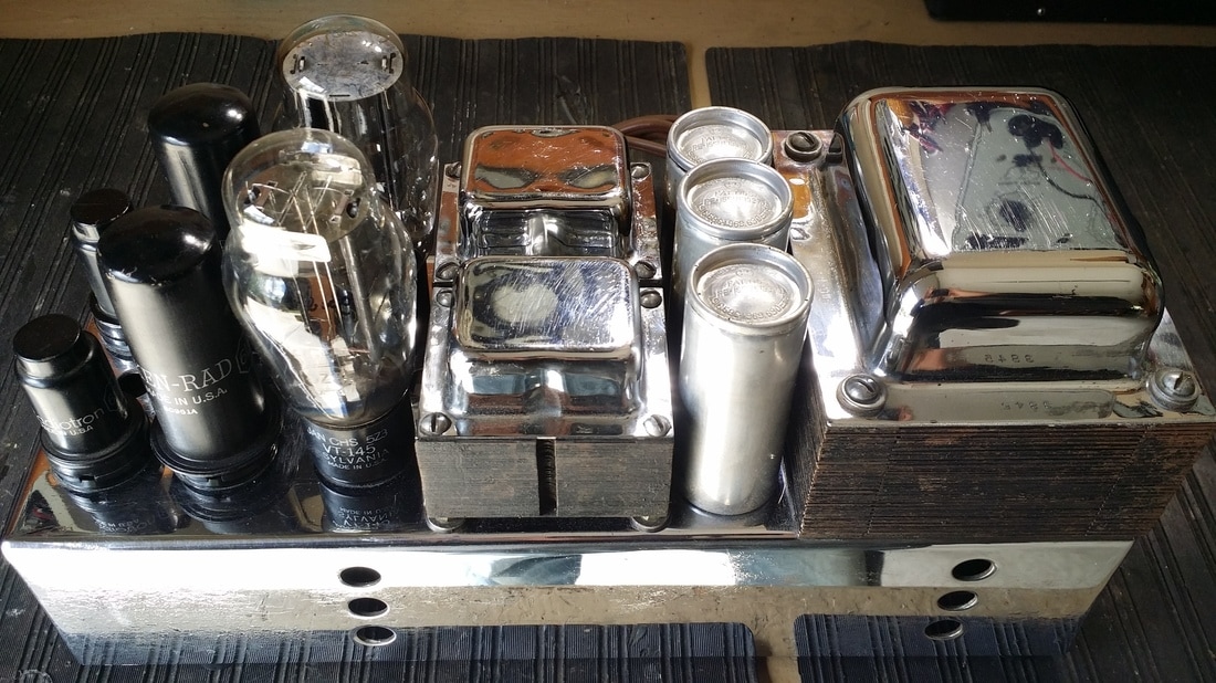
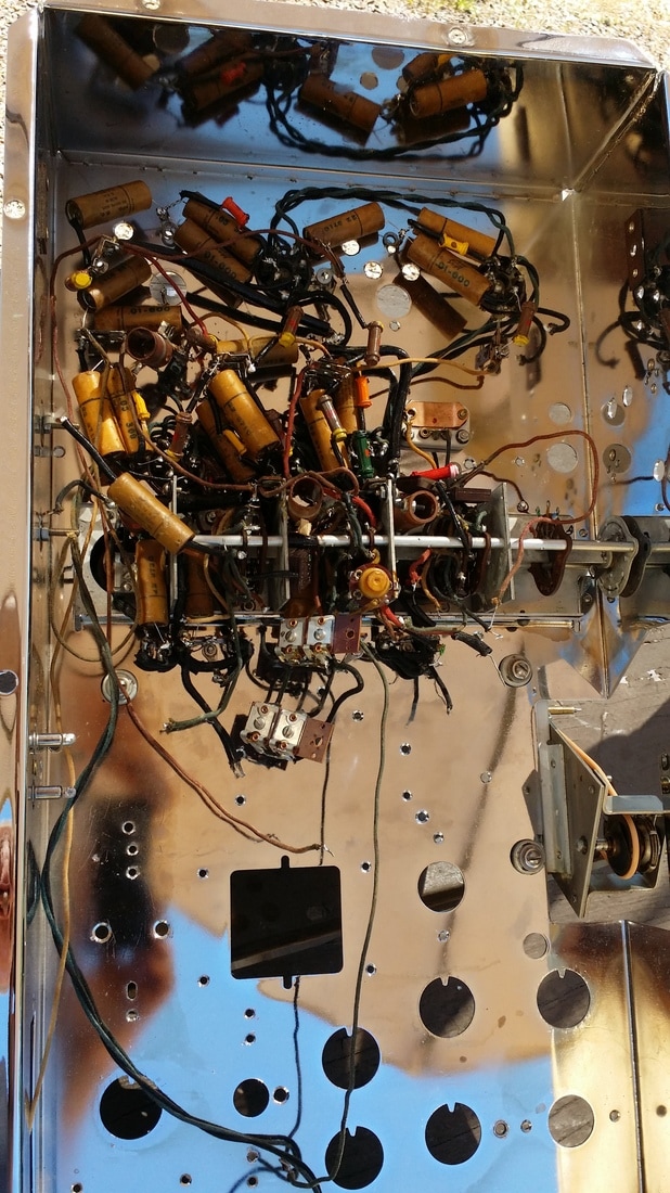
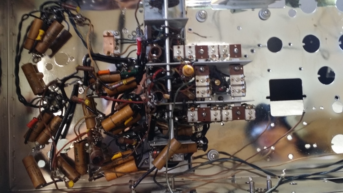
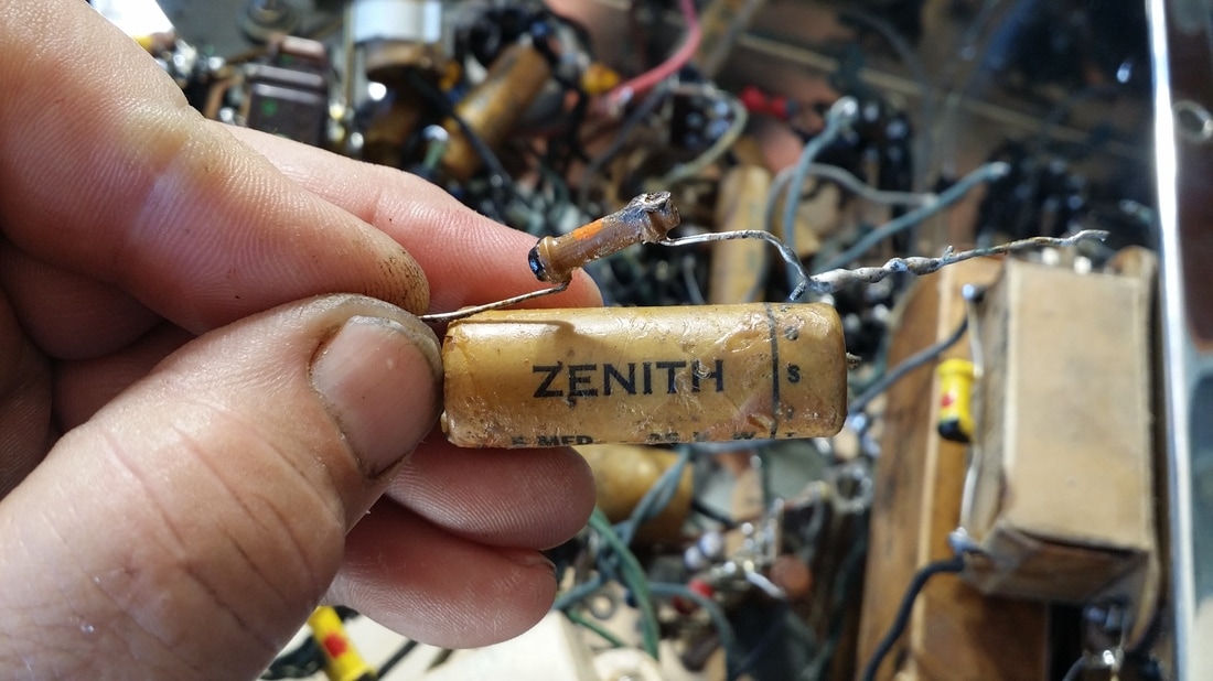
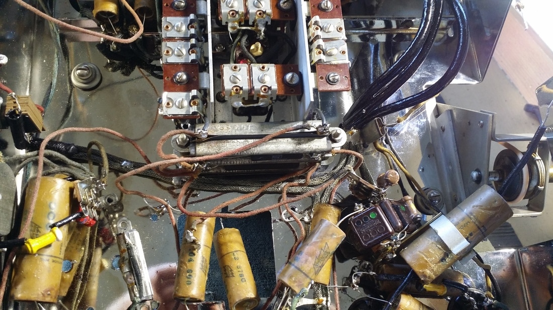
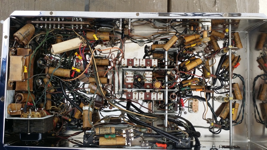
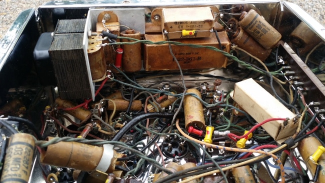
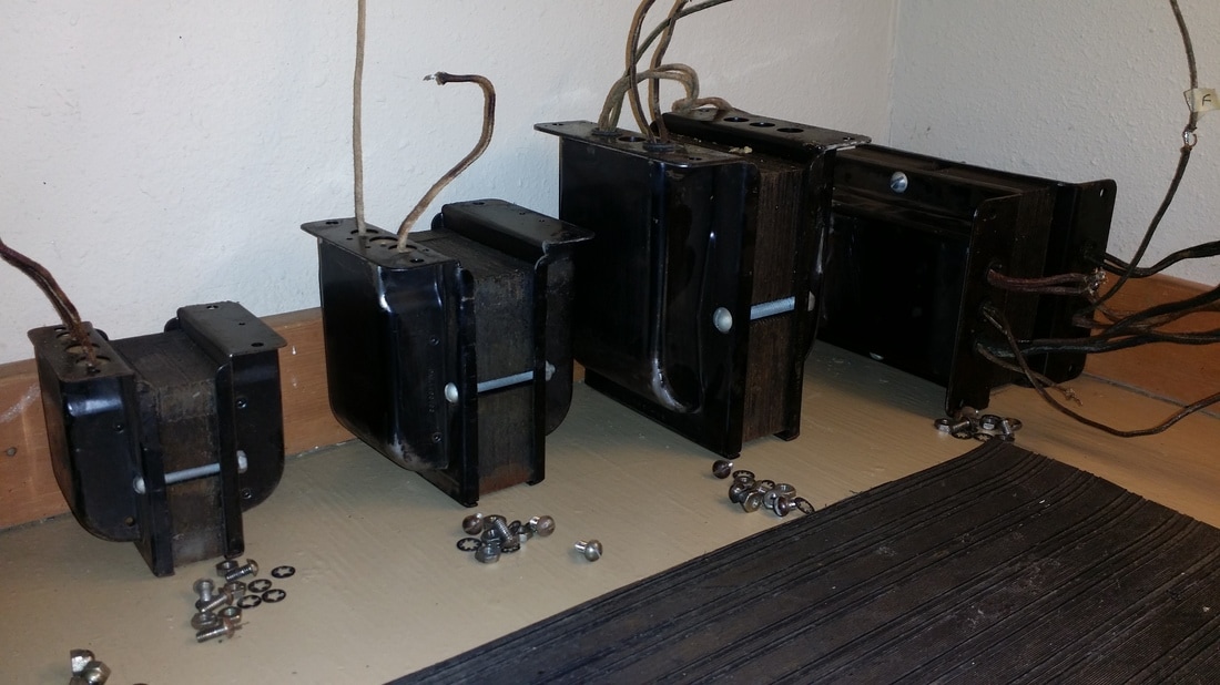
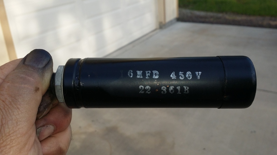
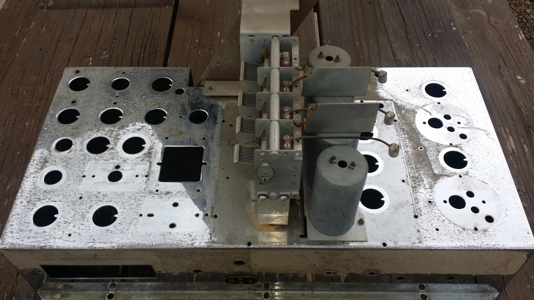
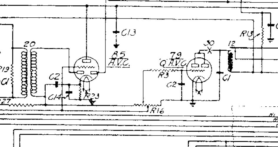
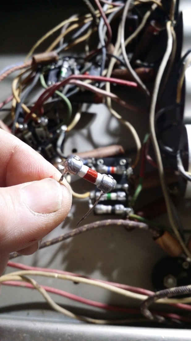
Other common issues include failure of the 3 interstage transformers pictured in back, above. And, the replacement of the two .5 uf paper capacitors. I restuffed/rebuilt all three of the interstage transformers and the metal-box capacitors for an original look.
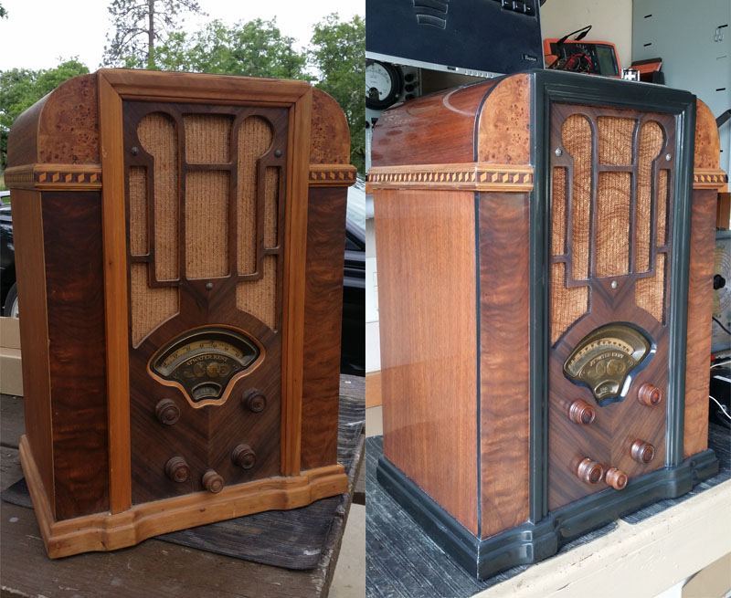
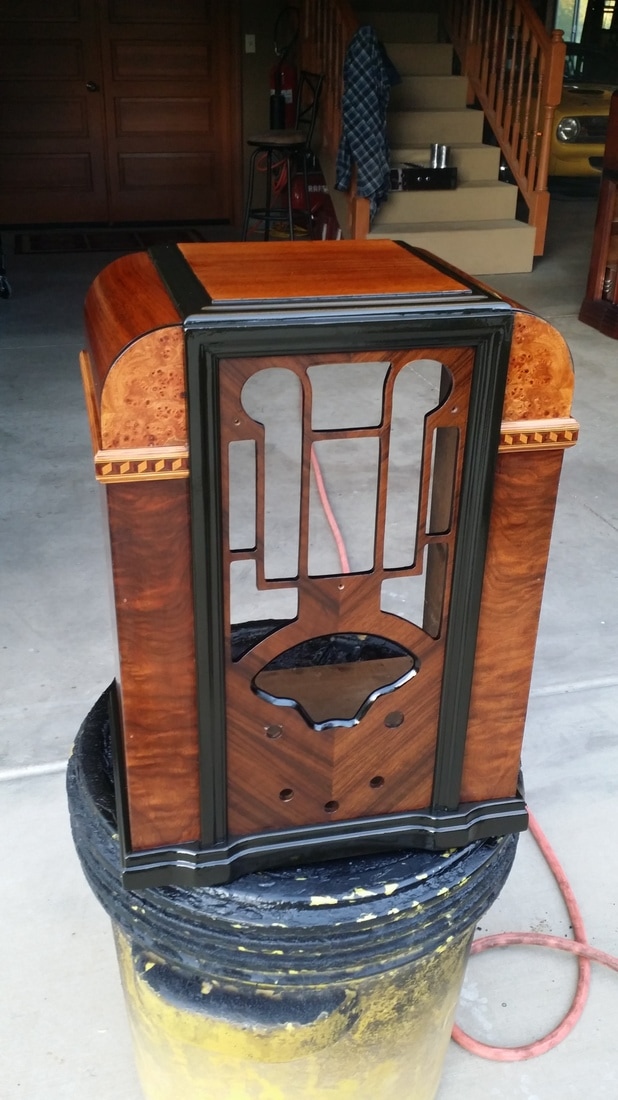
I was able to save the original crinkle finish with just a little touch-up as well as the finish on the board. Not so lucky on the other radio, but, more on that one later -


 RSS Feed