
Let me explain -
First of all this is not the best Remler Superheterodyne. It seems that "Best" is the fellow that designed and marketed this particular adaption of the Remler Super. It is distinctive because of the use of the fixed value dropping resistors for the audio tubes and the use of only 3 UV 299s in the IF section. The resistors look like a big fuse and are rated to drop 6V to 5V for a particular tube which is marked on the case/paper cover. Cool right? Well sort-of. The rest of the tube filaments are controlled by 2 variables. One must be used for the 3.3V UV299s and the other for the remaining tubes.
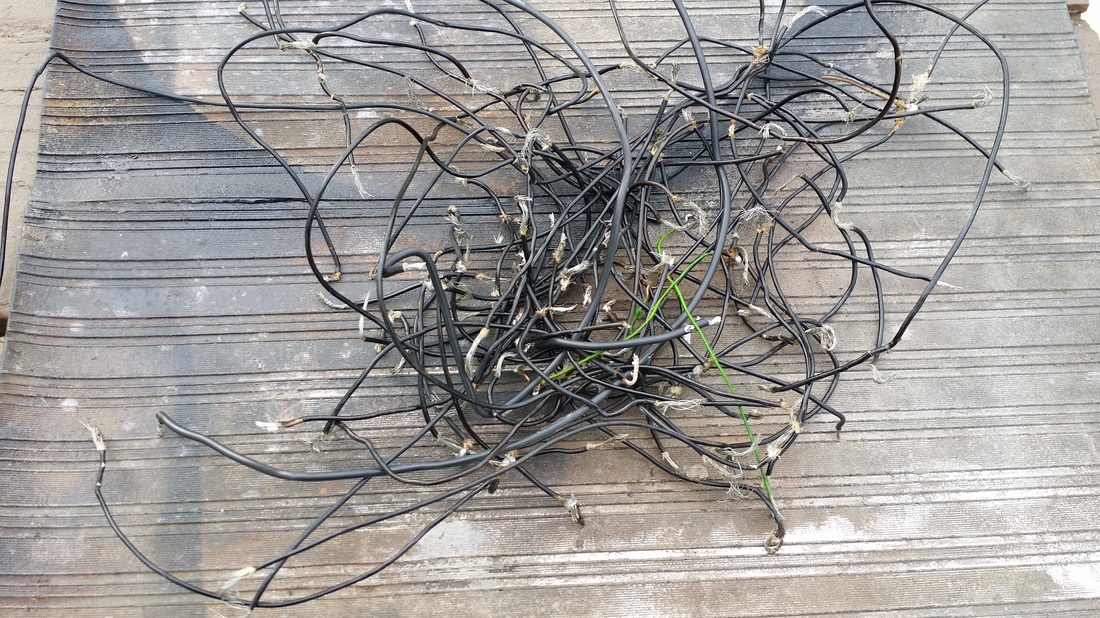
When I got this radio it was a mess. It had been wired with rubber insulated wire in a haphazard fashion, It had 4 of the little fixed resistors/holders controlling 4 separate tubes, only he used the wrong values. Two were for UV-201 (1 Amp) tubes. Then he had 1 correct rheostat and one that was 800 ohms which was not hooked to anything. He was also in the process of adding a 9th tube - not wired. Also, he had picked an oscillator coil that was a plug in variety, as recommended in the build documents. Only it wasn't an oscillator coil. It only had 4 contacts - two windings. It was missing the inner choke winding.
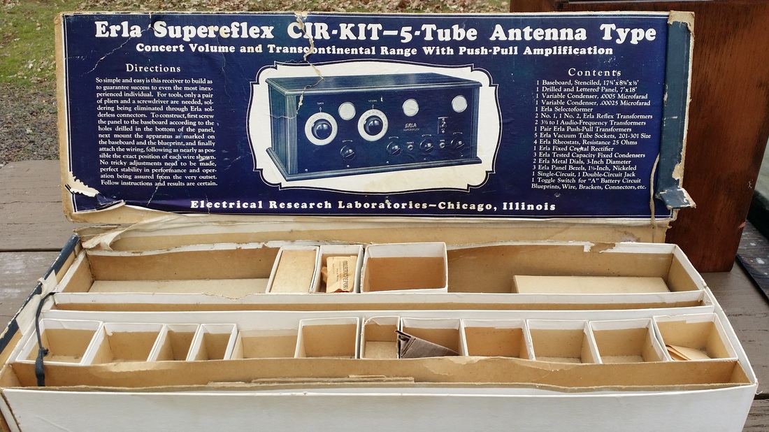
It makes you wonder: How many of these expensive projects ever really worked (see other examples below). But does illustrate the dedication and determination of the builder to succeed. To bad there was no e-Pay or Amazon back in those days. He could have just returned it!
First of all this is not the best Remler Superheterodyne. It seems that "Best" is the fellow that designed and marketed this particular adaption of the Remler Super. It is distinctive because of the use of the fixed value dropping resistors for the audio tubes and the use of only 3 UV 299s in the IF section. The resistors look like a big fuse and are rated to drop 6V to 5V for a particular tube which is marked on the case/paper cover. Cool right? Well sort-of. The rest of the tube filaments are controlled by 2 variables. One must be used for the 3.3V UV299s and the other for the remaining tubes.
When I got this radio it was a mess. It had been wired with rubber insulated wire in a haphazard fashion, It had 4 of the little fixed resistors/holders controlling 4 separate tubes, only he used the wrong values. Two were for UV-201 (1 Amp) tubes. Then he had 1 correct rheostat and one that was 800 ohms which was not hooked to anything. He was also in the process of adding a 9th tube - not wired. Also, he had picked an oscillator coil that was a plug in variety, as recommended in the build documents. Only it wasn't an oscillator coil. It only had 4 contacts - two windings. It was missing the inner choke winding.
It makes you wonder: How many of these expensive projects ever really worked (see other examples below). But does illustrate the dedication and determination of the builder to succeed. To bad there was no e-Pay or Amazon back in those days. He could have just returned it!
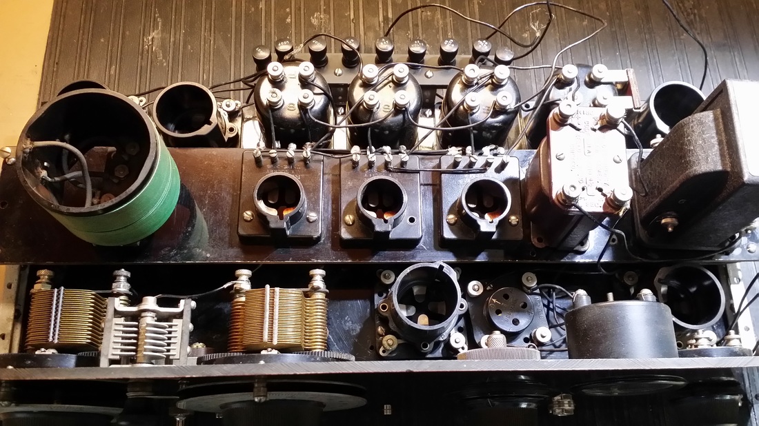
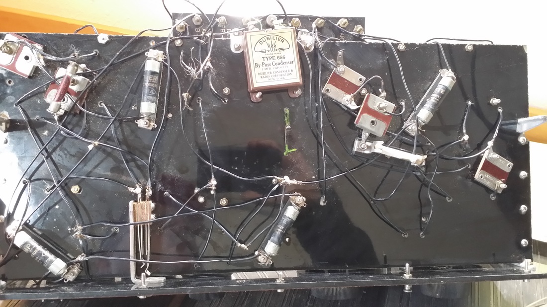
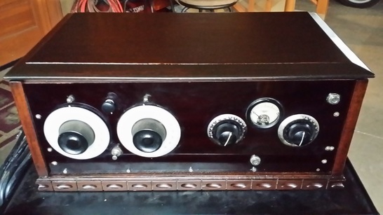
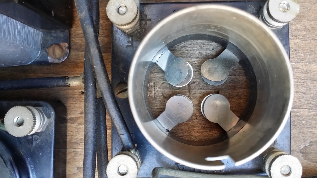
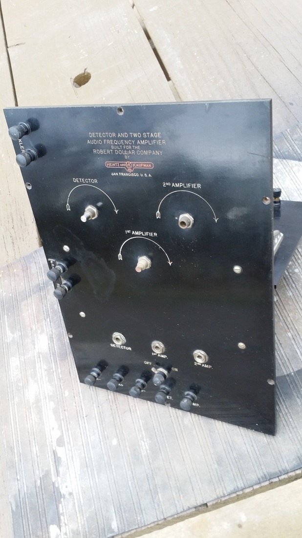
Above and below - As found.
So after examining the rather scarce information of the various versions of this design, which includes some of the early Scott supers, I decided that it most closely resembled the Best Super 8 and proceeded to reconstruct it as such.
Once finished I concluded that the moniker "best" was probably inaccurate for a very simple reason. Trying to regulate the RF, Oscillator and Detector tubes with only one filament control makes the radio nearly impossible to use. Certainly it has a poor performance in receiving all but strong local stations. It could easily be fixed by adding 2 more filament controls. Then you could even use a gaseous detector like the UV-200 (A). But no. it was not designed that way. The result was one stage either starving or swamping the next. Also the oscillator tended to stop. Turning up the filament voltage and then back down restarted it with a noticeable click.
Once finished I concluded that the moniker "best" was probably inaccurate for a very simple reason. Trying to regulate the RF, Oscillator and Detector tubes with only one filament control makes the radio nearly impossible to use. Certainly it has a poor performance in receiving all but strong local stations. It could easily be fixed by adding 2 more filament controls. Then you could even use a gaseous detector like the UV-200 (A). But no. it was not designed that way. The result was one stage either starving or swamping the next. Also the oscillator tended to stop. Turning up the filament voltage and then back down restarted it with a noticeable click.
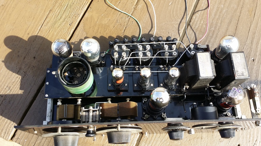
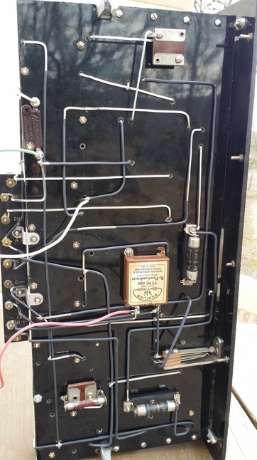
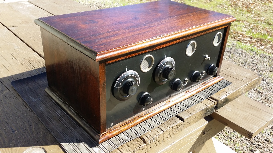
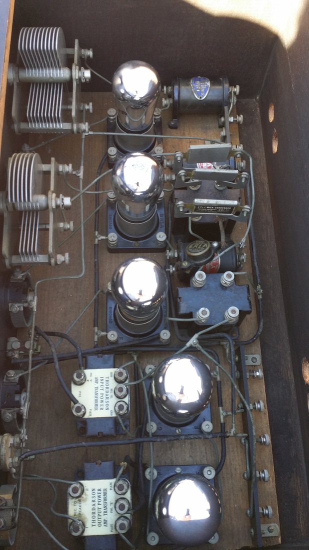
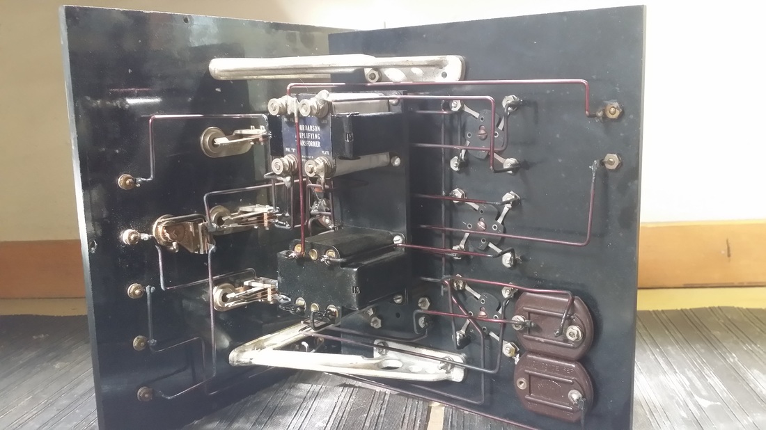
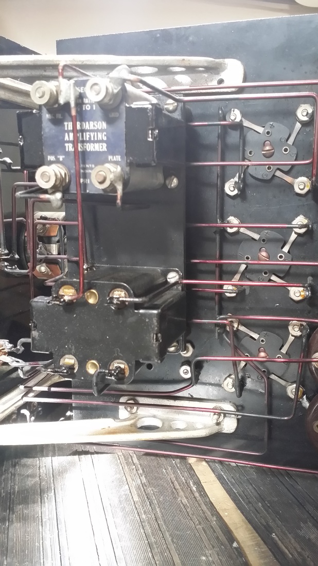
The "after" shots - Wired with square buss wire, avoiding the use of heat-shrink on the top side of the chassis. The colored wires are for the 3 "C" voltages.
I would not have wired it in this way. I would have used different routing for the conductors but in this case, I wanted to use the holes that the original builder drilled rather than adding a bunch of new ones. So I did the bet I could with what I had. I think I only added 2 new holes to the Bakelite panel.
I would not have wired it in this way. I would have used different routing for the conductors but in this case, I wanted to use the holes that the original builder drilled rather than adding a bunch of new ones. So I did the bet I could with what I had. I think I only added 2 new holes to the Bakelite panel.
Need some vintage wire?
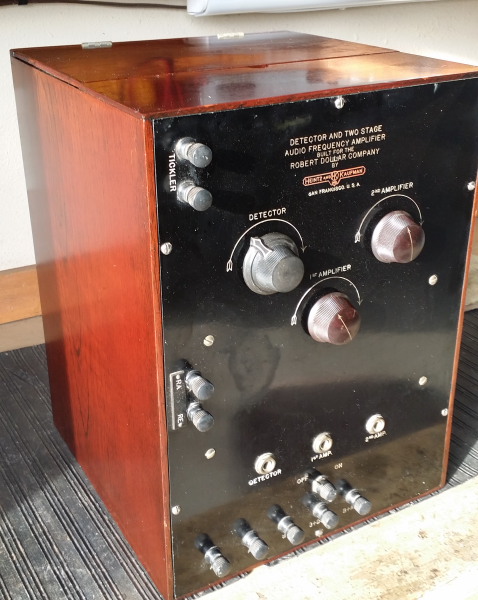
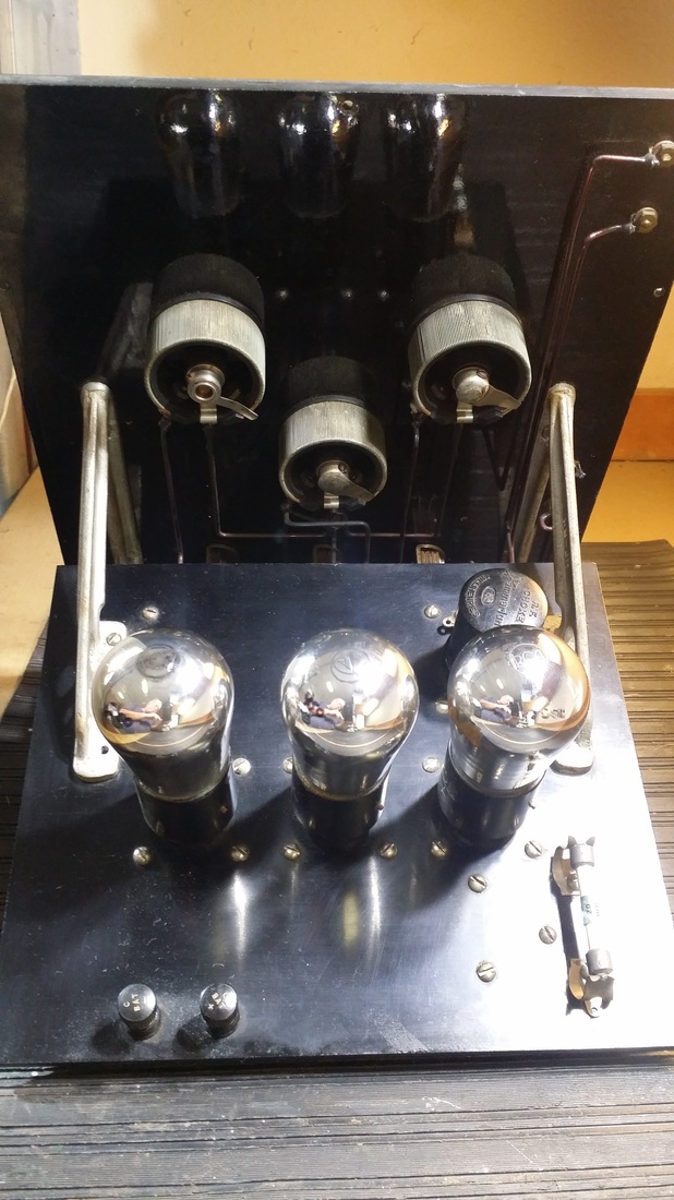
Reinstalled into the cabinet in which it was found.

 RSS Feed