RUSS' OLD RADIOS
  • HOME
  • FOR SALE
    • CURRENTLY AVAILABLE
    • DO IT YOURSELF SPECIALS
    • EXCEPTIONAL DEALS
    • WITH MP3 PORTS
  • RESTORATION
  • BLOG
  • BEFORE/AFTER
  • CONTACT US
  • UNIQUE RADIOS
  • 1920'S Superheterodyne

Remler Infradyne and Tube Substitution

12/19/2017

0 Comments

 
Picture
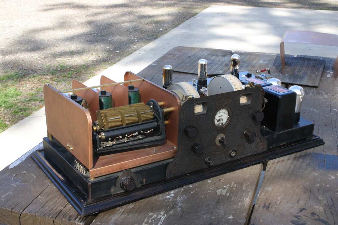
1928 Remler Infradyne, battery powered, 10 tube, superheterodyne, cabinet and shield removed for display

In the previous post the substitute UV 199 tubes are demonstrated in an early 1920s TRF radio. Now I wanted to test the UX 199/UX 120 versions along with another application for the UX 201A version.

I realized that there aren't many - any, small radios using the later UX tube versions in the museum display. There are a couple in storage, not easy to get to. There is the Thompson Minuet, I really did not want to pull it off of the shelf and risk damaging the speaker cone that Buford Chidester made for it. And then there is this really big  Remler super. Well at least the top cover was already removed for display.
Picture
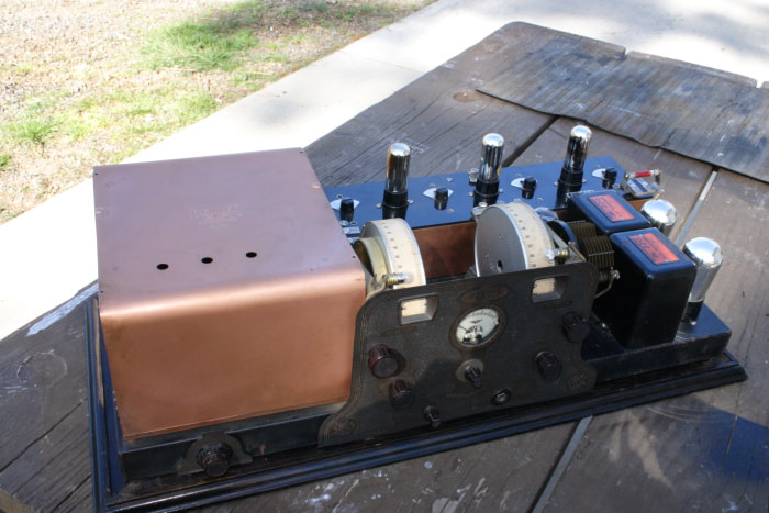
Shown with shield installed on the TRF portion

The Remler is a cool radio!

I had purchased it about 5 years ago along with about a dozen other radios at an auction near Portland. It always seems that radios come in bunches and I am always in a hurry to clean them up. I do test them, but, generally move on to the next one after as quickly as possible.

Now I had a little time to explore and the first thing I needed to do was verify that the unit was functioning normally. It Wasn't. The second RF section in the TRF wasn't contributing at all.


Picture
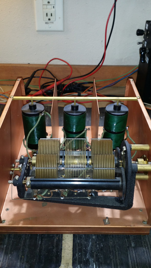
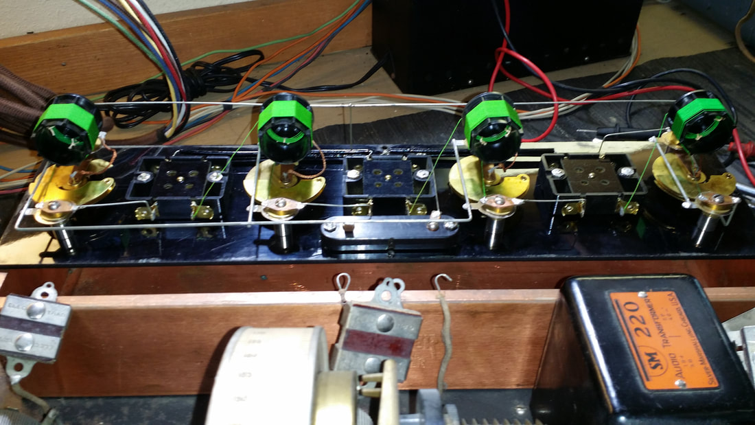
TRF section, tubes removed

It did not take long to find the problem which was a relief since there are a lot of moving parts and the potential for broken wires, but that was not it,

The second section of the tuning cap was shorted. This was not from broken parts but because of a wiring issue. The 3 sections of the ganged cap are isolated from each other until that little wire, seen near the bottom of the picture above is installed. On most tuning cap assemblies the moving plates (rotor) are all grounded to the shaft that moves them leaving the stationary plates (stator) to be connected in the grid circuit. On this assembly Remler had wanted to stagger the grounded plates - in other words the moving plates (rotors) in the center section were grounded. This must have confused somebody WHO grounded the stator as well as the rotor. I could tell from the obviously factory connections on the trimmer what the design configuration was.

Picture
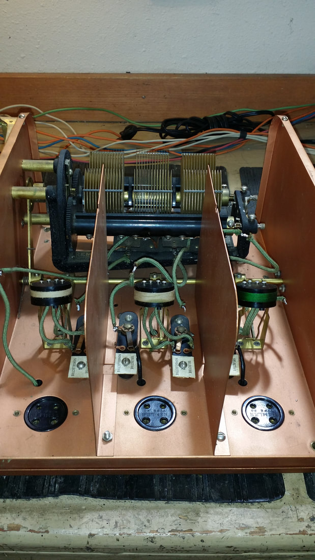
Primary windings removed from the coupling transformers to revel the moving secondary windings who's pitch is automatically adjusted as the tuning cap is turned.
The fix resulted in better gain from the TRF section.

I suppose that at This point I should explain that unlike any other early super that I have seen, This radio will operate as a superheterodyne OR as a TRF. And that is one of the reasons that I think it is so cool. With a "normal" super from this time you would tune and tune listening for a squeal and then tweak the IF and oscillator until you had a station. OR you would just have some noise - start over. On this radio you can turn up the TRF filament rheostat and get the same functionality as a 5 tube TRF, which is what it is in that setting. When a station is found turn down the TRF (you don't need that much input to the IF section) and adjust the super for the best audio. It really is much easier.

If you want to understand the other cool functions, like the IF that uses the sum of the freq. and local osc. there are a few good sites. Start at this one:

http://www.duanesradios.info/html/infradyne_superheterodyne.html

Now on to the tube substitution.

Below is a demonstration of the Infradyne:

Below, the 01A (201A) substitute is used in the 1st audio socket.
In the video below the 01A sub is used in the 2nd detector position with the superheterodyne section running.
During the testing process I decided to inspect the IF assembly. Below is the IF, removed and flipped over. IMO these non-potted IF transformers are so much easier to deal with than other manufactures units.
Picture
Inside of the Infradyne IF section
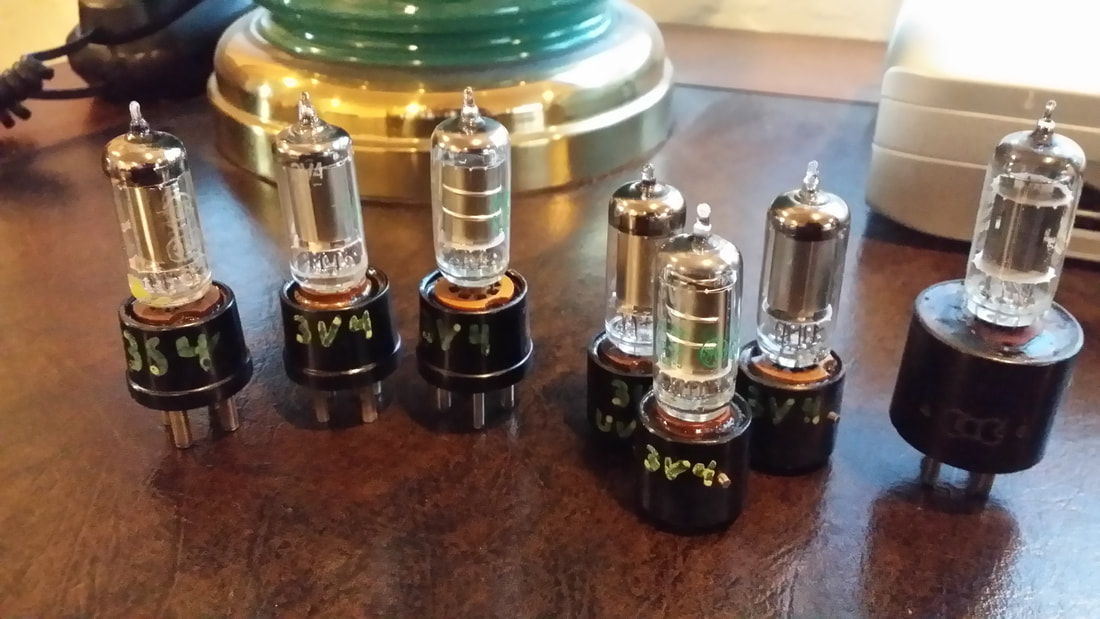
I decided to just go-for-it and replace all 3 of the UX 199s in the IF section. I believed that this was probably not going to work - but it did.  The higher gain of the substitute tubes along with other differences required retuning the IF.

Using the tree tubes there is a savings of 1/3A in the filament supply.
As one last note, I never did show or sub the UX 199 used as the oscillator since it is stuffed in behind the meter so close that it is almost impossible to get out.

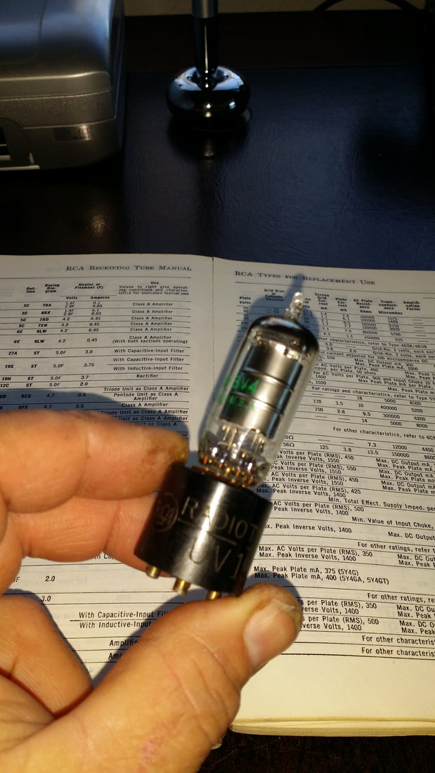
I used a 3S4 just to see if it would work, it does, but the 3V4 is probably better. In the case of the 3S4 the jumper between the plate and screen could be replaced by a resistor to reduce the screen voltage which is not required in the 3V4.

Well, this concludes this project, at least for now. I have another chrome plated monster to work on.

Russ

P.S. Don't miss Part I below.
0 Comments

No Substitute -

12/7/2017

5 Comments

 
OR is there - -
I just looked up 201/01A postings on E-Pay. It looks like prices are up since the low around 4 years ago. Then it was not uncommon to be able to buy these for $10 - $15. Looks like it is $20 - $25 now. One thing you can be sure of - they aren't making new ones.

There is plenty of history on the 201 online so some research should be done, if you are interested.

I have more than enough UX201s to last a long time, especially considering that the plastic base, long pin tube was really only original equipment for about a year with the previous versions running back to about 1920. And since I try to put the original brand/type of tube in my restorations - well, that is why I have plenty.

But, many people only care about the radio working - and being cheap (me too).

I have thought about this for a while and it is a sure thing that I am not the first. Here is how it goes - build a replacement for the UX201/01A for less than $2.50.

You are gonna' need a 4 pin base like off of an 80. Depending on your radio, this base may or may not need to have the side pin for the Bayonet/UV base - depends on how old your radio is. Then, a standard 7-pin miniature socket. These should both be available from your junk drawer.

Then look in your tube stash for a 6C4. I picked this tube for it's characteristics - basically it is 1/2 of a 12AU7.  It is called a power triode by RCA. If you don't have one, E-Pay has some for about $1, some NOS. I just bought 15, about half of them NOS for an average of $1.10 - Sorry, there will be more.

Then 4 wires and a jumper will connect the 2 sockets/plugs. Connect the 7 pin socket, pins 3 and 4 to the big pins, pin 6 goes to the small pin on the right (Pins up, big pins closest to you) and the plate to the remaining small pin. Then place a jumper between pin 3 (fil) and pin 7 on the 7 pin socket. This is the cathode connection.

To test as a 201 use the same settings as an 01A but you will need to lower the bias from about 48 to near 0.

In testing this tube works great as an audio amp including a 112 . I tested it in my AK 20 in all positions with setting as they were for the 201s and it worked great as a detector and audio amp improving tone and level some and about the same as the 201 in the RF amp sockets.

BUT, BUT it is a 6V tube. Yeah, it doesn't matter. It takes about 10 seconds to warm up. BUT, BUT, BUT the cathode will be damaged - well if it goes to "sleep", just run it at 6V in your tube tester for a while. In reality these tubes were often run at low filament voltages to keep noise down in audio circuits and as a way to get bias for finals - look up some of the Fisher amps using the 12AU7 and 12AX7. It will be fine.

Also it only draws .15A of filament current. This will make your power supply/battery happy.
Picture
The video, above, is of my AK 20C a 5 tube TRF.  At the beginning the radio is in operation with the original  201A/200A tubes - NOTE  the audio level. While it is running I sub in the 6C4. Necessary for the demo, don't do this unless you are very confident of your interstage trans. The sub takes a few seconds to warm up. Note the audio level - and hum. The higher gain is producing both. Turning down the vol/fil voltage will eliminate the hum.

This is both good and bad. The higher gain gets you higher volume, but may introduce some tuning issues. See the Wurlitzer C-3 demo below.


So a UX 201/01A sub is cool but what makes me nervous is testing with UV-199s and other more expensive/temperamental tubes.

I say temperamental since it seams that a UV or UX-199 can go to sleep just setting in it's box. Sure they can be rejuvenated, at the risk of destroying them. During the restoration process it sure would be nice to have a sub that doesn't cost $50 and up (metal base UV), then put in the correct tubes for display.

Again, looking in the inventory under cheap and plentiful I find the 3V4 miniature 7 pin tube. I have 12 of them. This tube is a pentode but don't let that bother you. The filament is a center tapped common cathode with the tap already jumpered to the suppressor grid. So one more jumper between the plate and screen and you have a triode.

https://www.radiomuseum.org/tubes/tube_3v4.html

The filament is 2.8V but running it at 3V should be no problem. The current draw is .05A. This is just perfect to replace both the UV and UX 199. COST?? - About $5 on Pay-Bay.
Picture
Go back to your parts box - assuming it is not still dumped out on the floor - and find another 7-pin mini base. Now, the UX-199 base is a little harder to find than the one for a UX-201. It has the same pin spacing and sizes but is over-all smaller in diameter. Good/bad news is that there are a lot of bad ones around. The UV-199 is harder to come by, even bad ones. Your are going to have to search for "display tubes" which should be priced at $1 or $2.
OK! this is as good a place as any to post:
THE PIN OUT ON A UV199 IS NOT THE SAME AS A UX199!!!!
Anybody trying to test one without knowing this will be fine until they hook up a UV199 and push the "TEST" button - and - BOOM goes the filament, since you just put plate voltage on it.

Examine the pin-out, courtesy of RM:

https://www.radiomuseum.org/tubes/tube_3v4.html
Picture
3V4 adapted to a UX-199 base
Picture
3V4 in a UV-199 Base. Sorry tar, resin and such are tough on fingers - -
On your tube tester, use an ADAPTOR for the UV based tube. Both should give you about 1500 GM on the settings for a 199 (or a 99 on most Hickok tube testers).
My Wurlitzer C-3 is demonstrated in the video above using the stock UV199 metal -based tubes. These test with a GM of 500-600 (good). These 3 tubes are worth about $150 if you can find them at all.

All 3 of the UV tubes are swapped out for the 3V4 sub with a Gm of 1500 - 2000.  The radio works well with more volume and sensitivity.  The demo continues with a station at the high end of the dial ~ 1300 kHz.

Later, on a station at 620khz there are more issues with oscillation. The higher gain of the sub tubes is causing both better sensitivity and oscillation. Decreasing the coupling (moving the coil)  reduces the osc. squeal, but the tuning becomes critical. The coupling adjustment is not fine enough to make tuning this part of the band practical. The radio could be modified to eliminate this issue, but that is not something I would want to do.

So there may be issues relating to the higher gain of the substitute tubes. These problems will increase with the number of sub. tubes employed. To this I should add that radios using a single or two tubes perform very well. I could not demo one of these for you since they don't produce enough audio to drive my RCA 103 speaker. Additionaly, it is safe to predict that 4 and 5 tube radios would need some modification to prevent the excessive gain from causing increasing problems with operation.

Keeping in mind that the objective was to produce a substitute tube for restoration/testing so as not to risk expensive UV type tubes, I think that this is a success.


OK, OK, just one more - for now.

How about the UX-120. This is the "power" triode output on many radios that use the 199s. The adaptor above is going to work in that socket but the B+ needs to be kept to 90V. How about using a 3S4 instead? It has about the same configuration s the 3V4 but a different pin-out.

I need to do more testing on the UX199 and UX120 subs. I will post further as results become available

If you find these posts useful, don't forget to check the "like" below. Thanks

Russ
Picture
P.S. ;-) Tube abuse

5 Comments

    Author

                         Russ Webb

    Picture
    Russ Webb & Fuzzy

    Best Buddy, Radio fixer


    Categories

    All
    All
    Antiques
    Electronics
    Radios
    Repair
    Restoration
    Travels
    Vintage

    RSS Feed

    Archives

    March 2023
    November 2022
    October 2022
    July 2022
    January 2022
    December 2021
    September 2021
    June 2021
    April 2021
    February 2021
    January 2021
    November 2020
    July 2020
    June 2020
    April 2020
    March 2020
    December 2019
    October 2019
    May 2019
    April 2019
    March 2019
    February 2019
    January 2019
    December 2018
    November 2018
    October 2018
    September 2018
    June 2018
    April 2018
    March 2018
    February 2018
    January 2018
    December 2017
    November 2017
    September 2017
    June 2017
    May 2017
    April 2017
    February 2017
    December 2016
    November 2016
    October 2016
    September 2016
    August 2016
    July 2016
    June 2016
    May 2016
    April 2016
    March 2016
    February 2016
    January 2016
    December 2015
    November 2015
    August 2015
    June 2015
    May 2015
    April 2015
    March 2015
    February 2015
    January 2015
    December 2014
    November 2014
    October 2014
    September 2014
    August 2014
    July 2014
    June 2014
    May 2014
    April 2014
    March 2014
    February 2014
    January 2014
    December 2013

CUSTOM DESIGN BY SUE WEBB  06/2013       Redesigned by Russ Webb     Approved by Fuzzy   Updated:  Pretty much all the time, but I forget to change this date
Proudly powered by Weebly
Photos used under Creative Commons from valart2008, rafeejewell