RUSS' OLD RADIOS
  • HOME
  • FOR SALE
    • CURRENTLY AVAILABLE
    • DO IT YOURSELF SPECIALS
    • EXCEPTIONAL DEALS
    • WITH MP3 PORTS
  • RESTORATION
  • BLOG
  • BEFORE/AFTER
  • CONTACT US
  • UNIQUE RADIOS
  • 1920'S Superheterodyne

What's the Worst That Can Happen?

11/18/2016

4 Comments

 
Picture
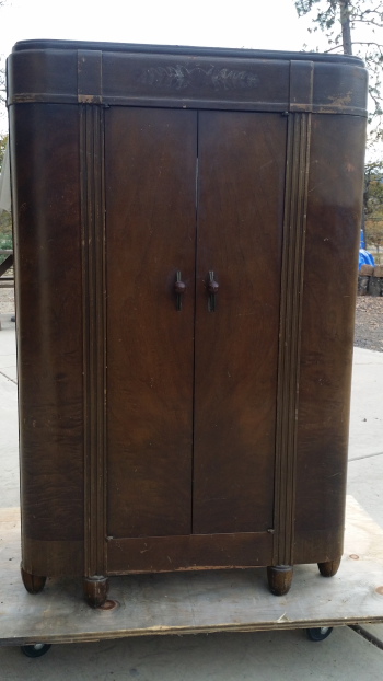
So you've started work on a radio project. You have a plan for the radio and the cabinet. Not much rust and the cabinet is only falling apart - a little. So what's the worst that can happen? Burn out an expensive tube?

How about a power transformer failure? These things happen, even if it seemed to be OK. Still the HV winding just goes up in smoke. No that's not it either. You can find a transformer and they're not that hard to replace.

No, the worst thing that could happen almost always sneaks up on you, since you seldom spot a defect until all the work is done (you think!?) Because, even if you've been nice, you haven't pulled on it's wires or twisted it's shaft - with a pair of pliers, a broken band switch is the worst thing that can happen. Or at least most people think so.

If you look and see a broken contact at least you know what is wrong. You know finding another one is unlikely. Though not absolutely true, it seems that the one in every radio is different. And if you were to find one, aren't there about a hundred wires and components hooked to one of those? Even then,  the replacement has to survive the operation.

Picture
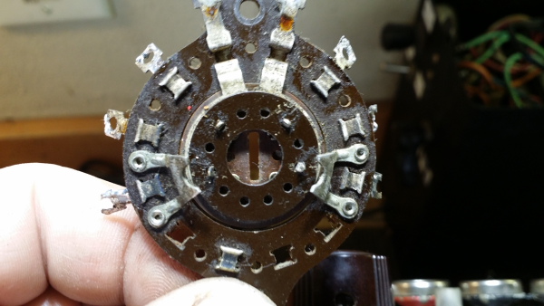
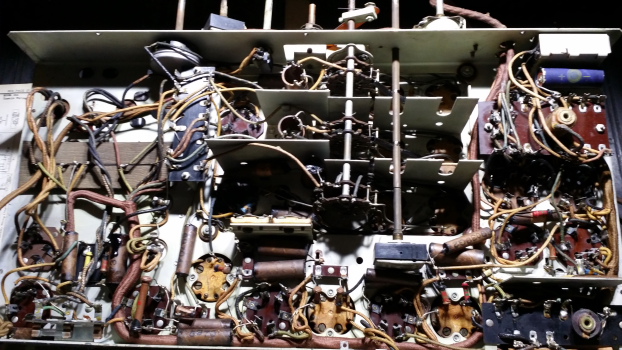
Wafer Switch Section Shares a Common Shaft with 4 or 6 or More Others
These things are tougher than they look. I'll bet that you have super glued one of these back together? If the wafer is broken, it is tough to fix. Like I said these are tough, cause they have to be. All those connections put a load on the structure. Then somebody gives it a twist, end to end like they were trying to start a fire, and it will survive. But super glue and epoxy often won't stick or be strong enough to hold a repair.

Just the idea of taking a band switch apart is enough to put a radio into the "parts" category. But it's not really that hard ;-)  Well, OK, it is hard, but I got a lot of experience while rebuilding the band switch on the 1000Z. I had thought that the wafers on that assembly exhibited bilateral-symmetry (meaning the left is the same as the right or in other words, you can't put it in upside down). I learned the hard way that both of the wafers in the center of the switch could be installed wrong.

So having learned the hard way, it is my conclusion that prior to disassembly a careful study of the switch and the schematic should be undertaken. This will take a while. It is time well spent since you have to identify the problem in the first place.

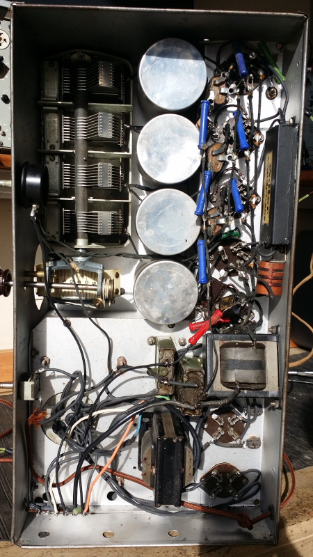
Most band switches are similar. Basically these allow an operator to switch coils needed for each band all at once. Before these switches a multi band radio had sets of coils that needed to be installed in plug-in sockets. This was OK for a Amateur (ham) operator but a bit much for the general public.

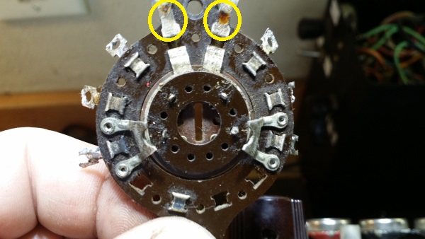
The fixed contacts around the perimeter usually go to the coils and associated components. Below, the 2 contacts circled in yellow are also fixed. BUT there is a hidden contact that slides along under the circular center wafer.
Picture
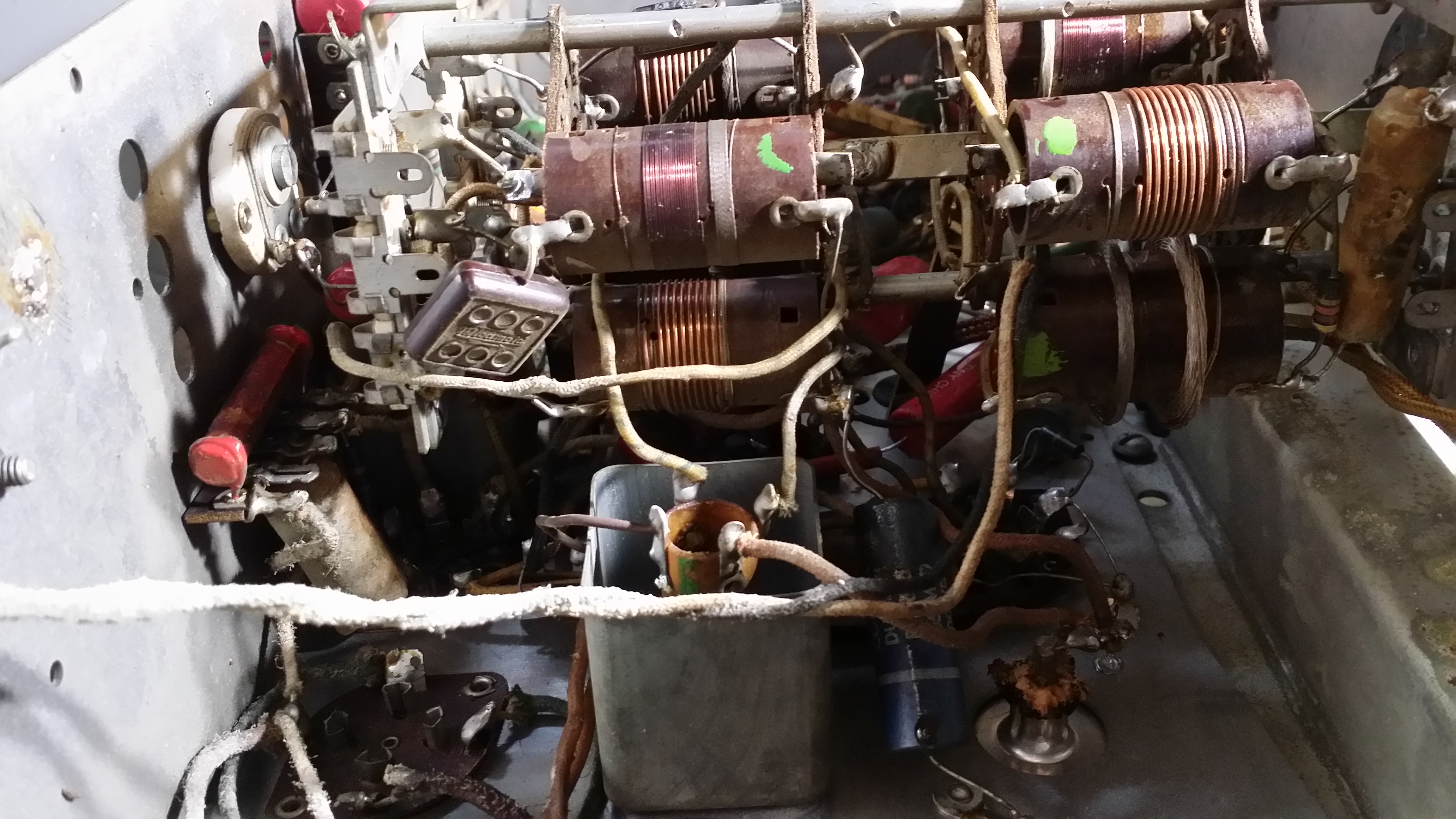
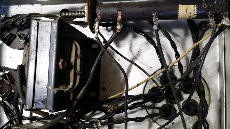
Band switch in Grunow radio chassis
Picture
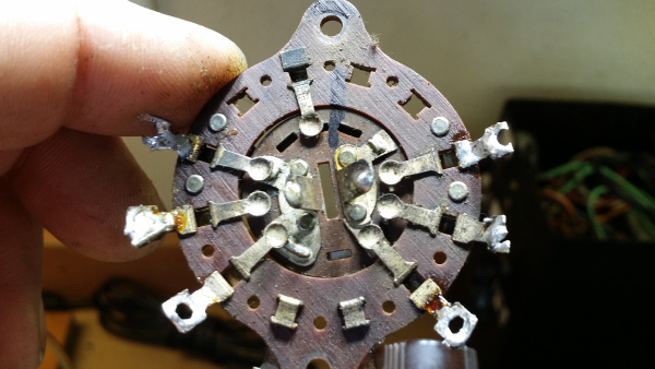
Above: the wafer that holds the sliding contacts in place is in the center. I have bent the retainers outward so that it can be removed.
Picture
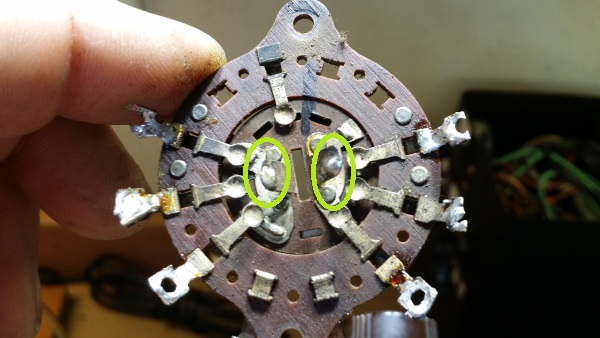
The other set of moving contacts. These are unusual and could have been replaced by adding another wafer to the assembly. They were used here with very flexible wire. shown below. View above is the reverse side of the assembly.

NOTE the index mark at the top! If you want to get these reassembled, index the parts.

Picture
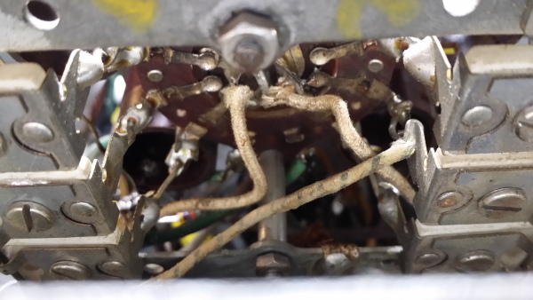
Above - The flexible wire connections
Picture
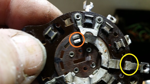
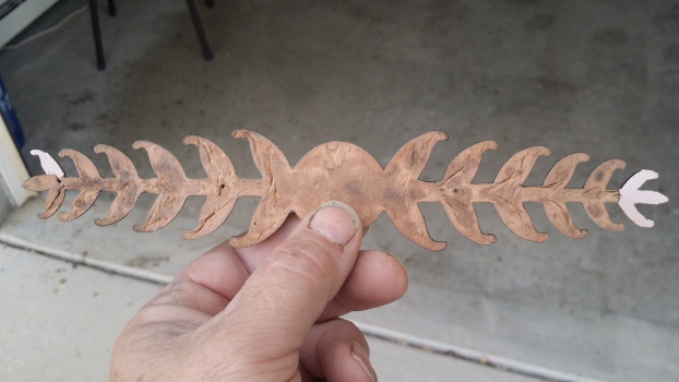
Above: The hidden contact (orange) that slides under the fixed connection (yellow) that allows contact with the connections along the perimeter.
The little sliding contact, above, was the problem in my switch. It had been pulled loose, probably by twisting the whole assembly beyond it's stops. I had noticed that the oscillator coils were not being switched. Fortunately, the little piece had been trapped under the center wafer or I would have had to borrow one from another switch. Unfortunately there was a similar failure on a second segment of the switch.

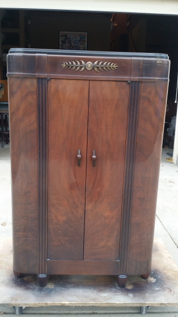
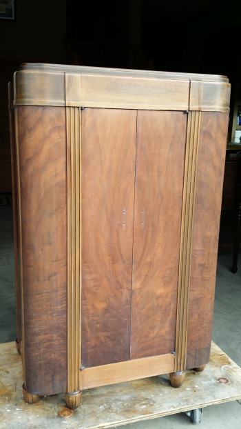
The 12 tube Grunow is now working as it should. I will add pictures of the radio when the cabinet is finished.


Notes about band switch failure:

When de-soldering never overheat the joint or pull hard on a component. The wafer can burn or char resulting in a carbon path (short) or worse a broken wafer or contact. It is often best to cut the component lead and then clean up the eyelet which will help avoid both of these issues.

As mentioned, these switches are designed to travel in a portion of 360 degrees. A five band switch will have more travel than a two band switch. If the switch is forced to move beyond the stops, contacts may be damaged. Look to see that the switch is moving as designed.

Contacts can become oxidized. I use De-oxit (black label) to clean and lubricate. Sometimes a bit of oil on the shaft where it passes through the chassis is needed.

Contacts can become bent. Watch to make sure that the contacts move - just a little - as the switch engages. This will indicate proper contact.

Switches that use flexible wire connections (rare) need to be inspected for broken wire.

Switch position is indicated and maintained by a ball/spring or just a spring/detent. This gives you the click, click as you turn the switch. These can be broken or, in the case of the small ball bearing, it can be lost.

Pressure or twist can put a load on the wafer causing it to warp over time. This may make the switch hard to move or even damage a contact.

Take pictures prior to disassembly and mark parts so that they can be reassembled properly.

Save band switches from "parts sets".

Watch contacts for arcing. Arcing is generally unacceptable in this type of switch and can cause a great deal of damage in a short time. Arcing generally indicates a problem either in the switch or the associated circuit.

A signal "sniffer" can help identify connection problems assuming that the radio is in good enough condition to be operated safely.

Most of all - have patience and good luck..
4 Comments

Top of the Line 1935 M-125 from GE

11/12/2016

1 Comment

 
Good news! The project pile is becoming much smaller.

Since restoring a similar model for a customer, years ago, I have always wanted one of these 12 tube consoles. It was the top of the line for GE. It seems to have been offered in 1934 as well as 35 maybe into 1936.
Picture
Very impressive cabinet
The finish had turned very dark but the cabinet was otherwise in good shape.
Picture
As found - except I had removed the upper trim
Under all of that yellowed finish were some very nice veneers. There was no delamination and very few dings and scrapes.
Picture
Stripped the old finish
They used what looks like "West Indian Laurel" at the base of the cabinet but did not carry  through from the sides to the front. Instead using a piece of mahogany that must be tinted to match.
Picture
Chassis "before" with only a couple of replacement parts
eThe 12 tube chassis has a tuning range that includes X Band, 140 kHz - 400 kHz,  and four more bands up to about 37mhz. It does not use an eye-tube. Push pull 42s are the audio output and a 6D6 is used as an RF amp. A search for the schematic will be more productive if it includes the RCA 281 which used the same chassis.

With a 20 ft. long wire antenna, this radio is sensitive and selective and compares well with more expensive, higher tube count, radios in everything except audio output. Thought it does have separate bass and treble controls, the lack of a tweeter is noticeable.

All of the electrolytic and paper caps were restuffed as well as most of the resistors. The dog-bone resistors were replace with replica units at a higher wattage.

The most significant problem was the failure of the interstage transformer that drives the pair of 42s. Fortunately I had an exact replacement on a parts chassis. I wish that they had used nuts and bolts, Instead these used bent tabs. It is easier to unbend them than rebending when putting them back.

The output transformer had also failed. I had several to choose from so that wasn't a problem either.
Picture
Backside of trim revels my repair/sculpting. Hoping it is not noticeable from the front
I have yet to see one  of these that did not have some damage to the repwood trim especially in the grill area. The center piece of trim over the speaker is unsupported at it's thickest point and subject to the vibration from the speaker. This lower portion is often missing. Thankfully not so on this unit. (See bottom picture)
Picture
Toned and finished, just needs to be rubbed out
Reassembled just in front of it's new home. This is a heavy sucker so moving it in pieces is a good plan.

I find it a bit odd that GE used such a small dial. Though this was the style for this model year, It is still considerably larger than on it's smaller siblings such as the M-51 or M-61.

All of the 7 control knobs actually have significant functions - sensitivity - bass - on/off - tuning (large knob) - band - treble - volume. Though they could have combined the on/off volume.
Picture
Just barely fit
1 Comment

1929 Northland Console with Shortwave and the B-1B Bomber

11/9/2016

4 Comments

 
Here is another VERY UNIQUE radio from the collection that Jerry gave me and very special history.

This one, possibly more so than the other rare radios already discussed, is a possible one-of-a kind.

Northland  was a radio company in  Minneapolis MN .that was in business from the mid/late 1920s to the early 1930s. All of the radios that exist seem to be rare, especially on the west coast. So it is rather unusual that we have two models on display, the latest being this high-boy console.

Even the design of this console is a bit unusual for 1929 since it incorporates a shortwave receiver. Shortwave listening in the US did not really catch on until later in the mid 1930s. Further indications of the rarity of this model are the complete lack of any pictures/info or even a schematic anywhere. For that mater, I don't even know if it had a model number. It has a nice brass plate stating the manufactures name and a ser. number but that is  all.
Picture
Cabinet in nice shape with original finish
The main chassis is a TRF receiver that will tune most of the modern broadcast band. It has three 224 tubes used as TRF amps, a 227 detector, a 227 first audio and two 245s arranged as a push-pull pair. What is interesting about this receiver is it is seemingly over-built.

Have you ever wondered why a manufacture did not add a little more gain - say one more stage of RF or audio amplification? Cost, is probably the answer, but I assure you that this chassis needs no more gain. The first 224 is directly coupled to the antenna - no antenna coil. By the time you get to the detector the signal is SO STRONG- well just let me say that one foot of wire antenna is more than adequate and that a local distance switch would have been nice. Then there one two stages of audio amplification ending in the 245s, PP through an output transformer that is just used as a choke - meaning that B+ is on the center tap of the primary and each plate is hooked to the ends as well as a high-impedance speaker. Interestingly enough, the transformer/choke does have a secondary that could drive a dynamic speaker, which had become more common by the time this radio was built.
Picture
OP Transformer showing the unused secondary/potted power supply wiring/voltage devider and taped-up repair work (not mine, as found)
That big resistor (above) had two open segments and though I first thought it was a replacement part, I now believe that it was original equipment.

At some point repairs had been made. In the process the cable to the shortwave receiver was completely removed. OH GREAT, and no schematic exists!

The first step was to rebuild the power supply which was potted in cans and then, just to make it harder to rebuild ;-) was enclosed in another enclosed section of the chassis with just the black, yes ALL black, wiring emerging.
Picture
Rewired and repotted supply that includes the power transformer and to large chokes - which fit in the box tightly.
Picture
Picture
Rebuilt/repotted filter cap can. The label does state the total capacitance but not the number of caps inside or the individual values. Being able to test a couple of the originals allowed me to guess at the values of the failed caps.
Picture
Rebuilt power supply ready to reinstall. The PP audio transformer needed to be mounted prior to inserting it back into the outer box or the mounting nuts/bolts could not be accessed.
Picture
Main chassis ready to install - sort of. There is still the issue of the missing cable to the SW section.
Picture
Globe tubes installed . A few areas of paint loss, but I decided to leave it with the original paint.
Video of broadcast receiver section in operation
OK, moving on to the shortwave receiver chassis. Now, I have already noted that the cable was missing, removed in a prior repair. Later I realized why the owner probably did not miss this loss of functionality - much. What I have not mentioned is the failure of both tuning mechanisms in both chassis. As was often the case in radios from this period, there were pot metal castings. Not the tuning caps, thankfully. These were high-quality. It was the dial indicator which is a hub and axil affair. It was built from two pot metal parts that fit into each other with the shaft from the tuning cap passing through the whole assembly.

SO, not only could the outer part (hub) swell up and freeze the assembly but the axil passing through it could also swell. GREAT. Had there not been some wear on the parts used in the main chassis I would have never gotten them apart. But after some lube and careful twisting - I did free this assembly. NOT SO LUCKY on the shortwave section.

NOW, a lot of old pot metal swells, splits, explodes (flings off pieces) and generally has the strength of hard mud. So, as much as I wanted to pry, heat it up or hit it with a hammer, I knew this was not going to help.

To make a long story short, I ended up cutting the dial wheel free from the hub and using the shaft of the nice tuning cap as the axil. Why could they not have built it this way to start with? It certainly moves smoother than the original design.
Shortwave tuner section
Now I needed to figure out how the missing cable was hooked up. There were several manufactures at the time offering SW adaptors but I could not find an example of a similar, factory installed, 1 tube receiver of this vintage. Many of the adaptors allowed the user to remove the first RF amp tube and insert a plug that would power the adaptor and provide a signal into the main chassis. That is not what we have here.

I analyzed the function of the on/off switch. It had the ability to switch off the filament of the single 227 tube used in this section and a lead out that was switched on when this section was off. Well it became apparent that this simple regen receiver was to be inserted after to the broadcast detector and the first 4 tubes on the main chassis were switched off while it was in use. So there goes all of that RF gain used for broadcast reception.  Yep, that is the way it worked and the reason that the original owner probably did not miss it much.

At first I thought that I would combine the antenna connections into one. That was not going to work. Loss was not a problem. the problem was that the main chassis got by swell on a foot or two of antenna wire while the SW section needed a LOOONG wire. Hooking the two together resulted in audio levels from the broadcast receiver that could not be attenuated below VERY LOUD!
Caution! regen squeal
So, the shortwave section worked - works, just not up to the performance of the broadcast receiver.

Tuning, as with most receivers of this type is a two fisted affair requiring back an forth between the tuning control and the regen control.  it does use plug in coils, of which I have three. The testing I have done seems to indicate a tuning range inside of the "police band" or about 1.4mhz to 3 MHz, possibly higher.
The only concrete information I have about this radio came from the guy that built it.

"Walter" signed both chassis with his full name and the date. I am not sure of the spelling of his last name but I think I will try an internet search with a few possibilities.

Thanks, Walter.
Picture
I moved this quote from Bob out of the comments so that nobody would miss it. VERY COOL thanks Bob!

11/9/2016 01:30:40 pmRuss,
Walter Albert Spivak was born 12 Aug 1909 in Minneapolis, Hennepin Co., Minnesota and died 29 June 2001 in Littlerock, Los Angeles Co., California. He was a white, male whose father was Jerome Spivak and mother was Ida Miller. His Social Security number was 548-09-7971. [Ancestry.com. U.S., Social Security Applications and Claims Index, 1936-2007 [database on-line]. Provo, UT, USA: Ancestry.com Operations, Inc., 2015.] [Ancestry.com. Web: Minnesota, Birth Index, 1900-1934 [database on-line]. Provo, UT, USA: Ancestry.com Operations, Inc., 2015] [Ancestry.com. U.S., Social Security Death Index, 1935-2014 [database on-line]. Provo, UT, USA: Ancestry.com Operations Inc, 2011]
In the 1920 Census, he was living at 2022, 2 ½ Street, Minneapolis City, Minnesota and was 10 years old. He was living with his:
father, A. Jerome Spivak, age 39, born in Minnesota. (Jermome’s father & mother were born in Bohemia), his occupation was a packer in a flour mill.
mother, A. Ida Spivak, age 40, born in New York, (Ida’s father was born in Germany and mother in New York)
brother, W. Edmund Spivak, age 14, born in Minnesota
sister, M. Edith Spivak, age 12, born in Minnesota
brother, L. Jermone Spivak, age 6, born in Minnesota
brother, W. Frank, age 3 and 9/12, born in Minnesota
sister, A. Liberty Spivak, age 1 and 2/12, born in Minnesota
[1920; Census Place: Minneapolis Ward 6, Hennepin, Minnesota; Roll: T625_834; Page: 20B; Enumeration District: 110; Image: 964]
In the 1930 Census, the family was at 2111 ½, 2 ½ Street South, Minneapolis City although it appears Edith had moved out, probably married. The father, Jerome was now a baker and there was no occupation listed for Walter. [1930; Census Place: Minneapolis, Hennepin, Minnesota; Roll: 1091; Page: 19A; Enumeration District: 0108; Image: 997.0; FHL microfilm: 2340826]
In 1930, Walter was a member of the Minnesota Society of Aeraunatical[sic] Engineers at the University of Minnesota. [Ancestry.com. U.S., School Yearbooks, 1880-2012 [database on-line]. Provo, UT, USA: Ancestry.com Operations, Inc., 2010.]
He appears in a city record in Bonner Springs, Kansas on 1 March 1945 with a household of 2 people. [Kansas State Historical Society; Topeka, Kansas; Collection Name: Population Schedules and Statistical Rolls: Cities (1919-1961); Reel Number: 16-664]
In 1952, Walter A. and Anna B. Spivak are living Santa Monica, California. [Ancestry.com. U.S. City Directories, 1822-1995 [database on-line]. Provo, UT, USA: Ancestry.com Operations, Inc., 2011.]
He and his wife appear to stay in California for the remainder of their lives.
(genealogy is my ‘other’ hobby)..
Cheers Bob

It turns out he became the Chief Engineer for North American and was involved with production of the XB-70 bomber (and probably quite a few other things.) In 1928-29 he was at the University of Minnesota and in August was probably working a summer job at the Northland radio plant in Minneapolis.

This URL takes you to an article about the plane and Spivak:
http://www.collectorsweekly.com/articles/capturing-a-generation-of-aviation-geniuses-and-their-incredible-flying-machines/


Picture
Walter Spivak, , is shown here in 1988 at the Rockwell facility in Palmdale, California, with his B-1B bomber.

Photo by: © Bob Seidemann
Used with permission:

4 Comments

    Author

                         Russ Webb

    Picture
    Russ Webb & Fuzzy

    Best Buddy, Radio fixer


    Categories

    All
    All
    Antiques
    Electronics
    Radios
    Repair
    Restoration
    Travels
    Vintage

    RSS Feed

    Archives

    March 2025
    November 2024
    December 2023
    March 2023
    November 2022
    October 2022
    July 2022
    January 2022
    December 2021
    September 2021
    June 2021
    April 2021
    February 2021
    January 2021
    November 2020
    July 2020
    June 2020
    April 2020
    March 2020
    December 2019
    October 2019
    May 2019
    April 2019
    March 2019
    February 2019
    January 2019
    December 2018
    November 2018
    October 2018
    September 2018
    June 2018
    April 2018
    March 2018
    February 2018
    January 2018
    December 2017
    November 2017
    September 2017
    June 2017
    May 2017
    April 2017
    February 2017
    December 2016
    November 2016
    October 2016
    September 2016
    August 2016
    July 2016
    June 2016
    May 2016
    April 2016
    March 2016
    February 2016
    January 2016
    December 2015
    November 2015
    August 2015
    June 2015
    May 2015
    April 2015
    March 2015
    February 2015
    January 2015
    December 2014
    November 2014
    October 2014
    September 2014
    August 2014
    July 2014
    June 2014
    May 2014
    April 2014
    March 2014
    February 2014
    January 2014
    December 2013

CUSTOM DESIGN BY SUE WEBB  06/2013       Redesigned by Russ Webb     Approved by Fuzzy   Updated:  Pretty much all the time, but I forget to change this date
Proudly powered by Weebly
Photos from valart2008, rafeejewell