RUSS' OLD RADIOS
  • HOME
  • FOR SALE
    • CURRENTLY AVAILABLE
    • DO IT YOURSELF SPECIALS
    • EXCEPTIONAL DEALS
    • WITH MP3 PORTS
  • RESTORATION
  • BLOG
  • BEFORE/AFTER
  • CONTACT US
  • UNIQUE RADIOS
  • 1920'S Superheterodyne

What's the Worst That Can Happen?

11/18/2016

4 Comments

 
Picture
So you've started work on a radio project. You have a plan for the radio and the cabinet. Not much rust and the cabinet is only falling apart - a little. So what's the worst that can happen? Burn out an expensive tube?

How about a power transformer failure? These things happen, even if it seemed to be OK. Still the HV winding just goes up in smoke. No that's not it either. You can find a transformer and they're not that hard to replace.

No, the worst thing that could happen almost always sneaks up on you, since you seldom spot a defect until all the work is done (you think!?) Because, even if you've been nice, you haven't pulled on it's wires or twisted it's shaft - with a pair of pliers, a broken band switch is the worst thing that can happen. Or at least most people think so.

If you look and see a broken contact at least you know what is wrong. You know finding another one is unlikely. Though not absolutely true, it seems that the one in every radio is different. And if you were to find one, aren't there about a hundred wires and components hooked to one of those? Even then,  the replacement has to survive the operation.

Picture
Wafer Switch Section Shares a Common Shaft with 4 or 6 or More Others
These things are tougher than they look. I'll bet that you have super glued one of these back together? If the wafer is broken, it is tough to fix. Like I said these are tough, cause they have to be. All those connections put a load on the structure. Then somebody gives it a twist, end to end like they were trying to start a fire, and it will survive. But super glue and epoxy often won't stick or be strong enough to hold a repair.

Just the idea of taking a band switch apart is enough to put a radio into the "parts" category. But it's not really that hard ;-)  Well, OK, it is hard, but I got a lot of experience while rebuilding the band switch on the 1000Z. I had thought that the wafers on that assembly exhibited bilateral-symmetry (meaning the left is the same as the right or in other words, you can't put it in upside down). I learned the hard way that both of the wafers in the center of the switch could be installed wrong.

So having learned the hard way, it is my conclusion that prior to disassembly a careful study of the switch and the schematic should be undertaken. This will take a while. It is time well spent since you have to identify the problem in the first place.

Most band switches are similar. Basically these allow an operator to switch coils needed for each band all at once. Before these switches a multi band radio had sets of coils that needed to be installed in plug-in sockets. This was OK for a Amateur (ham) operator but a bit much for the general public.

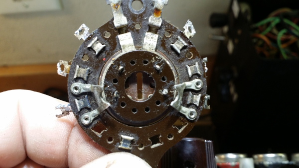
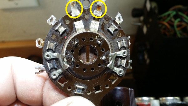
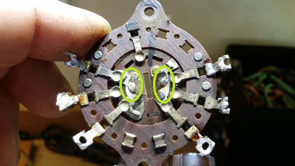
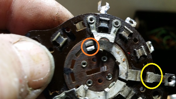
The fixed contacts around the perimeter usually go to the coils and associated components. Below, the 2 contacts circled in yellow are also fixed. BUT there is a hidden contact that slides along under the circular center wafer.
Picture
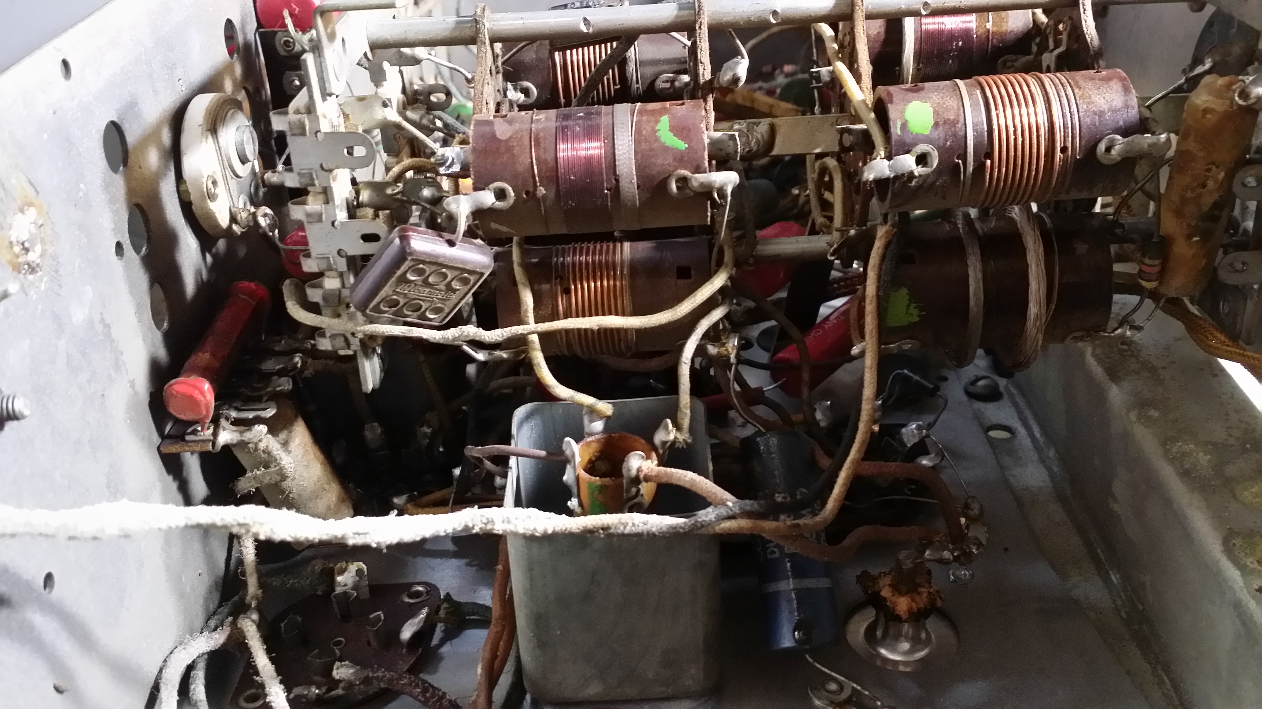
Band switch in Grunow radio chassis
Picture
Above: the wafer that holds the sliding contacts in place is in the center. I have bent the retainers outward so that it can be removed.
Picture
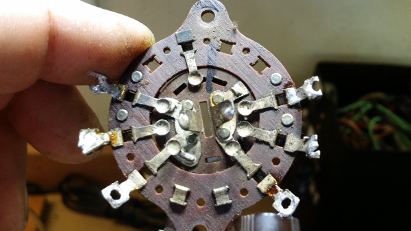
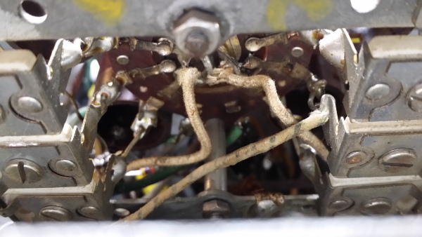
The other set of moving contacts. These are unusual and could have been replaced by adding another wafer to the assembly. They were used here with very flexible wire. shown below. View above is the reverse side of the assembly.

NOTE the index mark at the top! If you want to get these reassembled, index the parts.

Picture
Above - The flexible wire connections
Picture
Above: The hidden contact (orange) that slides under the fixed connection (yellow) that allows contact with the connections along the perimeter.
The little sliding contact, above, was the problem in my switch. It had been pulled loose, probably by twisting the whole assembly beyond it's stops. I had noticed that the oscillator coils were not being switched. Fortunately, the little piece had been trapped under the center wafer or I would have had to borrow one from another switch. Unfortunately there was a similar failure on a second segment of the switch.

The 12 tube Grunow is now working as it should. I will add pictures of the radio when the cabinet is finished.


Notes about band switch failure:

When de-soldering never overheat the joint or pull hard on a component. The wafer can burn or char resulting in a carbon path (short) or worse a broken wafer or contact. It is often best to cut the component lead and then clean up the eyelet which will help avoid both of these issues.

As mentioned, these switches are designed to travel in a portion of 360 degrees. A five band switch will have more travel than a two band switch. If the switch is forced to move beyond the stops, contacts may be damaged. Look to see that the switch is moving as designed.

Contacts can become oxidized. I use De-oxit (black label) to clean and lubricate. Sometimes a bit of oil on the shaft where it passes through the chassis is needed.

Contacts can become bent. Watch to make sure that the contacts move - just a little - as the switch engages. This will indicate proper contact.

Switches that use flexible wire connections (rare) need to be inspected for broken wire.

Switch position is indicated and maintained by a ball/spring or just a spring/detent. This gives you the click, click as you turn the switch. These can be broken or, in the case of the small ball bearing, it can be lost.

Pressure or twist can put a load on the wafer causing it to warp over time. This may make the switch hard to move or even damage a contact.

Take pictures prior to disassembly and mark parts so that they can be reassembled properly.

Save band switches from "parts sets".

Watch contacts for arcing. Arcing is generally unacceptable in this type of switch and can cause a great deal of damage in a short time. Arcing generally indicates a problem either in the switch or the associated circuit.

A signal "sniffer" can help identify connection problems assuming that the radio is in good enough condition to be operated safely.

Most of all - have patience and good luck..
4 Comments
Harry link
12/6/2016 12:46:32 pm

Tried to fix a broken wafer years ago...the super glue traveled down several wafers...everything got frozen...it became a parts set!

Reply
Eddie
10/13/2019 06:25:54 pm

Should warn people not to power up a bandswitch for a week or 2 after cleaning it with DeOxit or any spray with naphtha propellant. I cleaned a Hallicrafters S-40B bandswitch, then turned it on. In a few minutes it had "crackles" in the audio which slowly built up into hash, then I saw arcing in the bandswitch - it burned a track. Luckily I was able to clean it up and interchange a pair of wafers to get a good one where the B+ was. I figured the wetting down "activated" some grime and triggered an arc-track. If you agree - perhaps post a warning.

Reply
Russ
10/15/2019 08:22:42 am

Eddie,

I agree that this is a possibility. I vaguely remember this happening years ago to me, but this would be a very low percentage of the switches that I have cleaned.

A better warning would be to advise a visual inspection of the wafers for burns or other possible conductive traces as part of the cleaning. Additionally, though time consuming, techs might want to be aware of contacts with high voltage on them and be cautious. I have heard of several models that are prone to arcing due to switching considerable voltage and/or currents, These would require additional drying time or possibly a flush with denatured alcohol.

In general, having to wait weeks prior to testing is not something most of us have the patience for.

These comments are visible in the post so people can take note of the issue.

Thanks

Russ

Reply
Peter E Olesen
11/26/2020 08:37:32 pm

Have a Philco 118 with a jammed bandswitch. Will take your advice and be careful in trying to loosen it up. thank you for the blog. Peter Olesen.

Reply


Leave a Reply.

    Author

                         Russ Webb

    Picture
    Russ Webb & Fuzzy

    Best Buddy, Radio fixer


    Categories

    All
    All
    Antiques
    Electronics
    Radios
    Repair
    Restoration
    Travels
    Vintage

    RSS Feed

    Archives

    March 2023
    November 2022
    October 2022
    July 2022
    January 2022
    December 2021
    September 2021
    June 2021
    April 2021
    February 2021
    January 2021
    November 2020
    July 2020
    June 2020
    April 2020
    March 2020
    December 2019
    October 2019
    May 2019
    April 2019
    March 2019
    February 2019
    January 2019
    December 2018
    November 2018
    October 2018
    September 2018
    June 2018
    April 2018
    March 2018
    February 2018
    January 2018
    December 2017
    November 2017
    September 2017
    June 2017
    May 2017
    April 2017
    February 2017
    December 2016
    November 2016
    October 2016
    September 2016
    August 2016
    July 2016
    June 2016
    May 2016
    April 2016
    March 2016
    February 2016
    January 2016
    December 2015
    November 2015
    August 2015
    June 2015
    May 2015
    April 2015
    March 2015
    February 2015
    January 2015
    December 2014
    November 2014
    October 2014
    September 2014
    August 2014
    July 2014
    June 2014
    May 2014
    April 2014
    March 2014
    February 2014
    January 2014
    December 2013

CUSTOM DESIGN BY SUE WEBB  06/2013       Redesigned by Russ Webb     Approved by Fuzzy   Updated:  Pretty much all the time, but I forget to change this date
Proudly powered by Weebly
Photos used under Creative Commons from valart2008, rafeejewell