
OR, What to do with that old desk-top computer tower.
Four or five years ago the hard drive on my HP Media Center desk-top was dying along with Win XP support. It seemed wasteful to throw it out after all it was only 10 years old (ancient). So it sat in the garage until it got in the way.
Surely there must be something useful in all of those drives, memory and processors. Na, not really, except maybe the 300W power supply. These supplies provide 3.3, 5, 12 and -12 volts, well filtered with lots of current available. Do any of these voltages seem familiar? Well for me I quickly realized that this would make a great supply for those old 1920's tube radio filaments. Fifteen amps at 5V. You can run a lot of 01As off of that and a few (dozen) more 199s from the 3.3V. Too bad that the supply is not isolated and has no HV output.
Still it looked like an interesting project so I removed the supply and scrapped the rest. It took about an hour to replace the electrolytic caps which are usually the cause for failure in these devices.
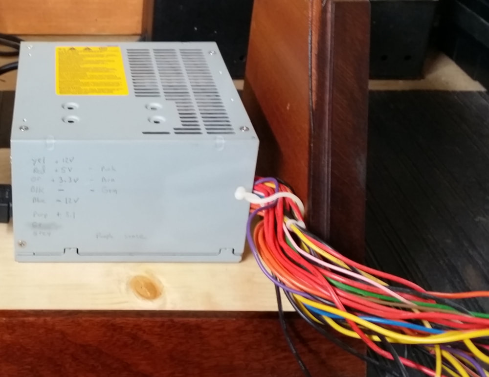
Lotta' wires -
These supplies can be purchased new and are rated/sized by wattage. This one is about 300W but you can get bigger and smaller ones. All of them have a lot of duplicate connections. Besides the output voltages there are several connections for protection circuits that must be connected to prevent the supply from shutting down. But mostly, there is a lot of duplication.
The conductors come out in a wad. I would prefer a bit more order but I was not going to redesign the supply. Since the supply is of the switching variety, you might find as much as 60V on any conductor as measured to ground. This could work - but not well, especially if you wanted to connect your receiver to earth ground.
The conductors come out in a wad. I would prefer a bit more order but I was not going to redesign the supply. Since the supply is of the switching variety, you might find as much as 60V on any conductor as measured to ground. This could work - but not well, especially if you wanted to connect your receiver to earth ground.
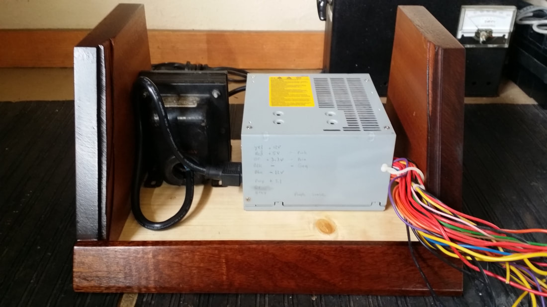
Add Isolation Transformer -
If you traveled to Europe in the 1960's, you might have carried one of these adaptors with you - just to run your US electric shaver. Not so necessary now and likely to put a dent in your airline weight allowance - or anything it crushes in your suitcase - but great to convert to an isolation transformer (left of the PS).
So now I had isolation.
I should mention that both of these parts/assemblies could add a significant cost to this project IF you have to buy them, but, they should be relatively easy to scrounge.
So now I had isolation.
I should mention that both of these parts/assemblies could add a significant cost to this project IF you have to buy them, but, they should be relatively easy to scrounge.
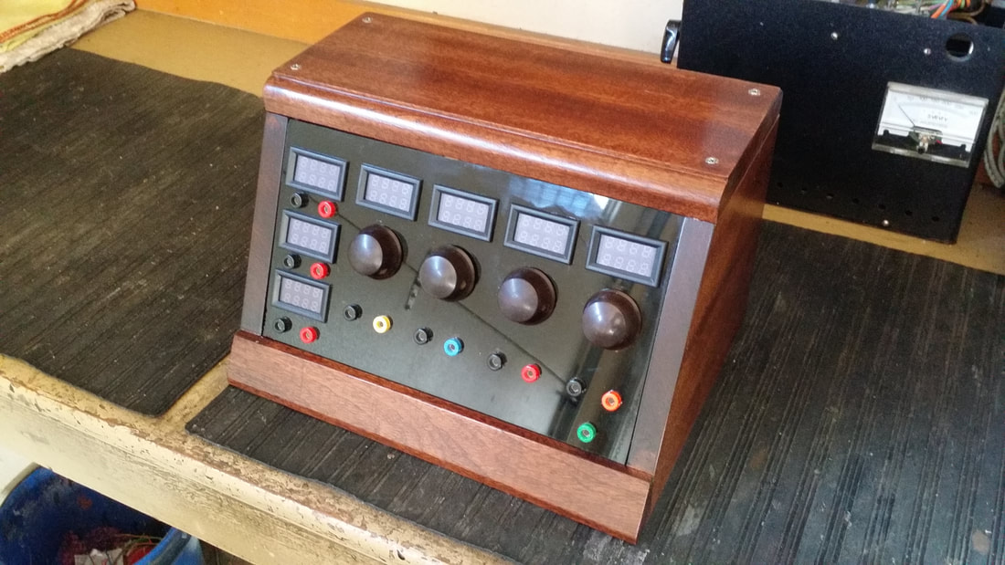
WOW it's almost done -
NOT! Now I needed to hit the internet, since, I could have built the HV supplies and the metering, but why spend a week on a $3 part?
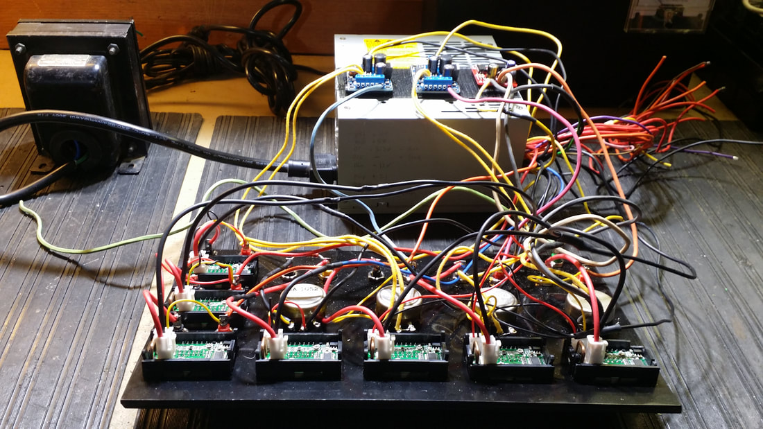
Most of what I needed was available on E-Pay or Mouser and when all was done it is interesting to note that the meters and inverter supplies cost about the same as the connectors. The banana plugs and alligator clips all came from Mouser, quick and easy. Trying to figure out what to buy on E-P was a bit more challenging.
I needed A, B and C voltages. The A and C were already available from my old computer supply but B+ would need inverters. I had plenty of 12V, so an inverter that would give me up to 200V running off of a 12V source was needed. There are plenty of cheap, mostly Chinese, supplies on E-Pay. None of them have schematics or specs beyond absolute ratings. The same can be said for metering.
I needed meters suitable to monitor the B+ (200V). It would be nice if they could be used for the A and C voltages as well. For about $3, inc. shipping, I found these. They also incorporated an amp meter good to 10A.
The 3 inverter supplies I chose could produce about 5W output. So as voltage-out increases current must decrease. At 180V that is about 27ma. Good enough for several 171As and 110ma at 45V, good for a lot of 01As or 199s. Fortunately they can protect themselves from over-current. UNFORTUNATLY both the meters and the inverters are common ground.
The 3 inverter supplies I chose could produce about 5W output. So as voltage-out increases current must decrease. At 180V that is about 27ma. Good enough for several 171As and 110ma at 45V, good for a lot of 01As or 199s. Fortunately they can protect themselves from over-current. UNFORTUNATLY both the meters and the inverters are common ground.
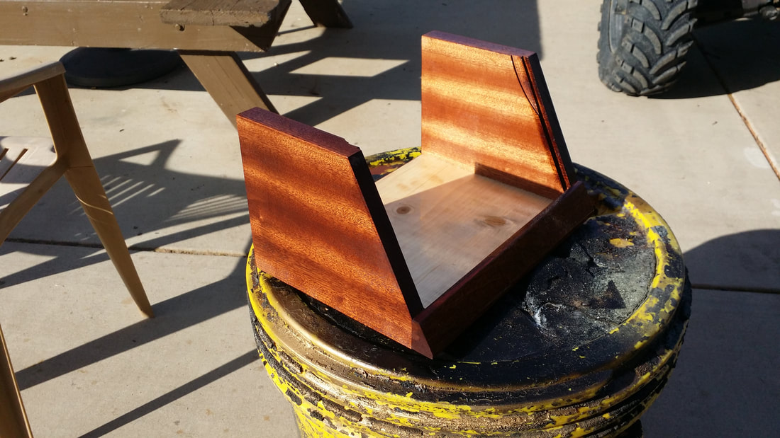
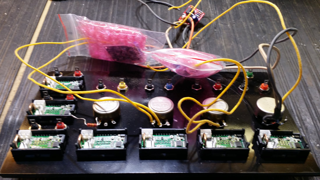
I was also going to need a cabinet. Something resembling a 20's radio would be great. Something with a small footprint would be better. The top is screwed on so it can be removed for service and the front panel is only held by friction/fit so it too can be popped out for service.
I bought a rough, 1' thick mahogany plank. I needed about 2 board feet for this project at a cost of about $6 per BF. I saved the rest. I thought that the slanted panel look would be accommodating on the bench and used a piece of 1/4 inch plastic for the panel with the back side painted black.
Cutting all of the holes in the plastic panel was a pain - probably the hardest part of this project. But, I managed to get it close enough on the first try.
As mentioned, the PS was going to be common ground whether I liked it or not. Really not to big a deal but issues include:
Current metering - since the meters measure amps through a shunt to ground (return), the current must be added if more than one ground is used UNLESS the device has separate isolated return(s). If each A, B or C voltage is being supplied to a separate, isolated, device no problem using each meter to monitor current consumption. SEE the video in which I use the A supply to monitor all current consumption. A meter with the shunt on the + side would have been much better allowing metering on each source. Also, the meters require 4V - 28V for their own supply, which is also common ground.
No output can be arranged in series. For example 100V + 100V = a short since the + can't be wired in series to the next source ground.
Issues for isolation to earth ground. Note that I added a green ground connection, which works for me since the shop is the only building on the ground and electric co's transformer. Performance elsewhere might be noisy - at best. Isolation transformer required.
C voltage is available from the computer supply but care must be observed in wiring. From my supply I can generate up to -12V but the meters will not measure - voltage. This means that the + side of the meter must be to common ground and 4V to 28V must be provided to run the meter without causing a short. An additional C voltage could be added using another variable. No current will be indicated by the meter since the C connection on your old radio draws almost no current. The C source needs a load resistor - about 100K, just to keep the associated rheostat within a reasonable range. My control is 5K to 25K. If your control is 0 - 25K, add a series 5k resistor.
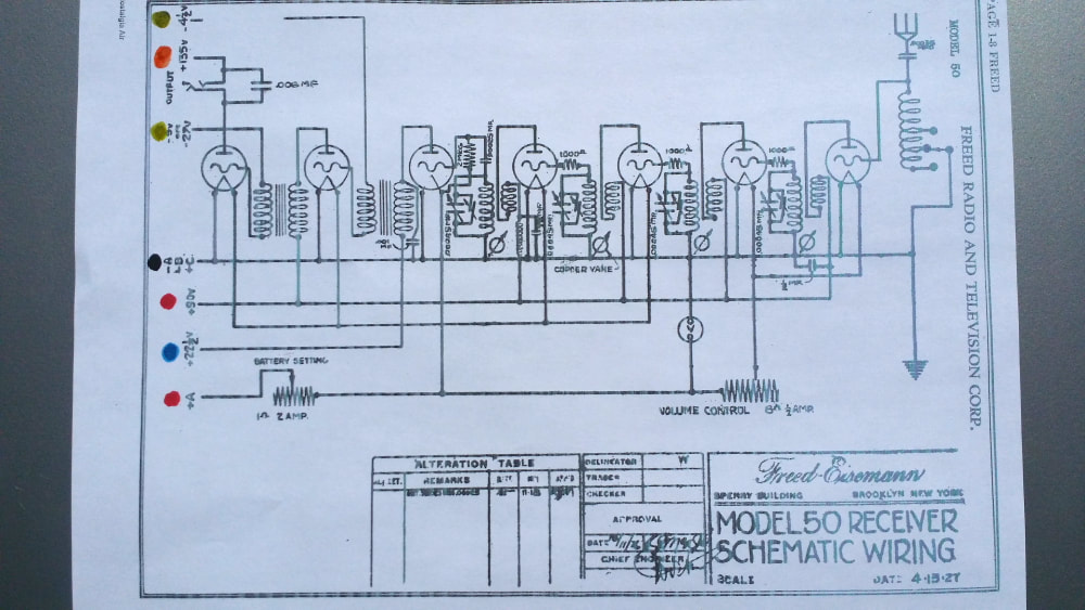
Schematic for the Freed Eisemann test subject showing the power connection color code used on the PS.
The Freed Eisemann 50 is a 6 tube TRF with 01As in all positions except the AF output being a 171A.
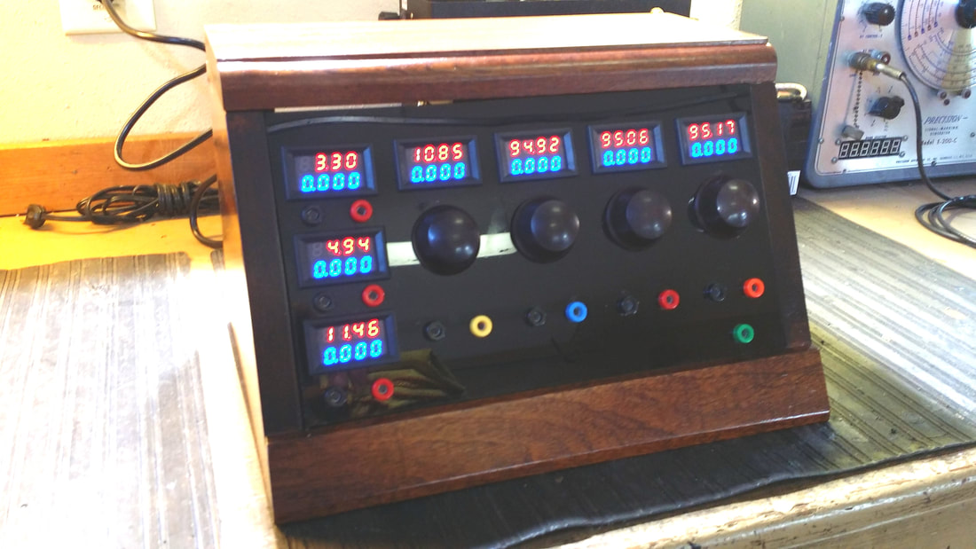
All of the metering really help in trouble-shooting 20's radios.
There is a small amount of hum but it is coming from my part 95 transmitter rather than this supply.
Note that the B+ current indicated on the 5V supply meter is about 15ma (1,242 B+ off to 1.257 B+ on).
ONE MORE NOTE on these meters - One reason that they may be so cheap is that the 3rd decimal point never lights - 99V reads 99.00 but 100V reads 1000.
Also, cool in the dark - see video.
Russ
Russ
UPDATE: In a related discussion on ARF there was some desire to raise the voltage on the 5V supply to near 6V. A simple modification to the 5V metering will raise the 5V supply to 5.6V and the 12V supply to 12.8V. This is accomplished by dropping the voltage on the pink wire by connecting a 2K resistor from that conductor to ground (any of the black wires). It is likely that 6V or higher can be achieved through other modifications, but, using a resistor smaller than 1.5K will cause the supply to shut-down.
5.6V is more than enough to power 01As and the like, allowing for some attenuation through the radio's filament control.
5.6V is more than enough to power 01As and the like, allowing for some attenuation through the radio's filament control.

 RSS Feed