

With the receiver chassis sent off to the chrome shop it's time to move on to the power/amp chassis.
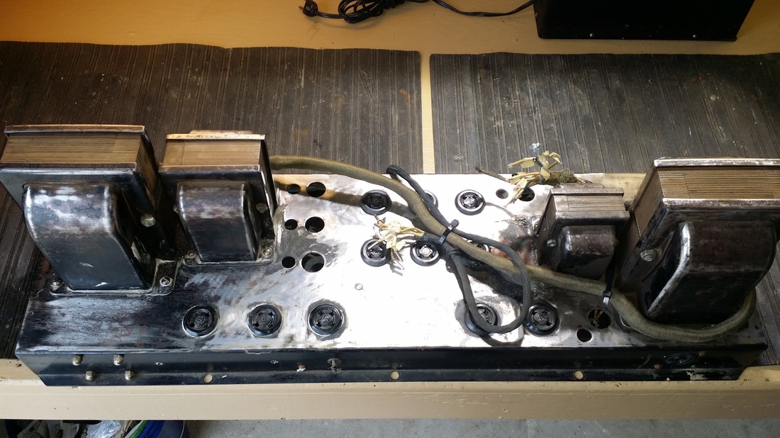
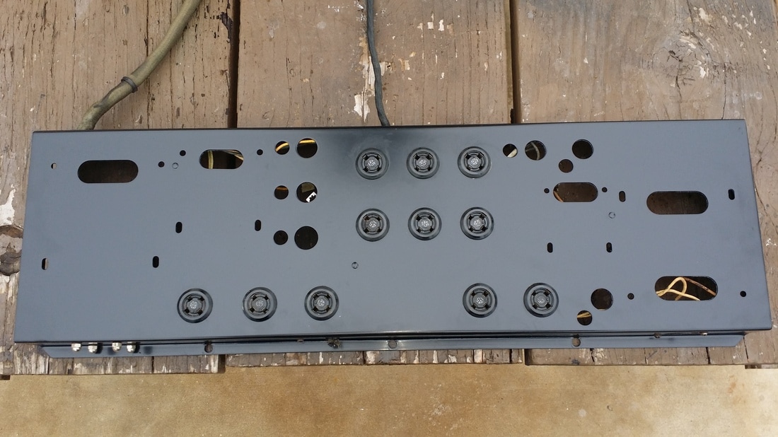
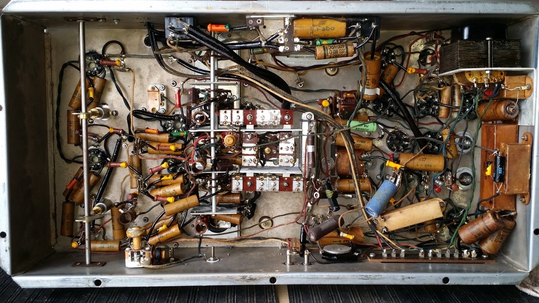
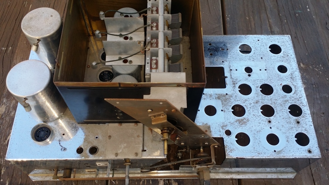
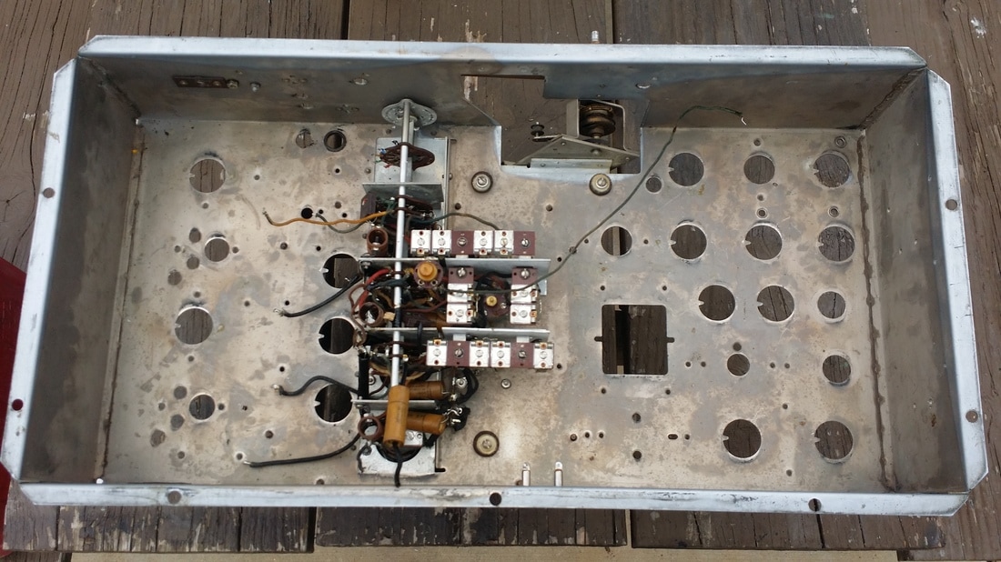
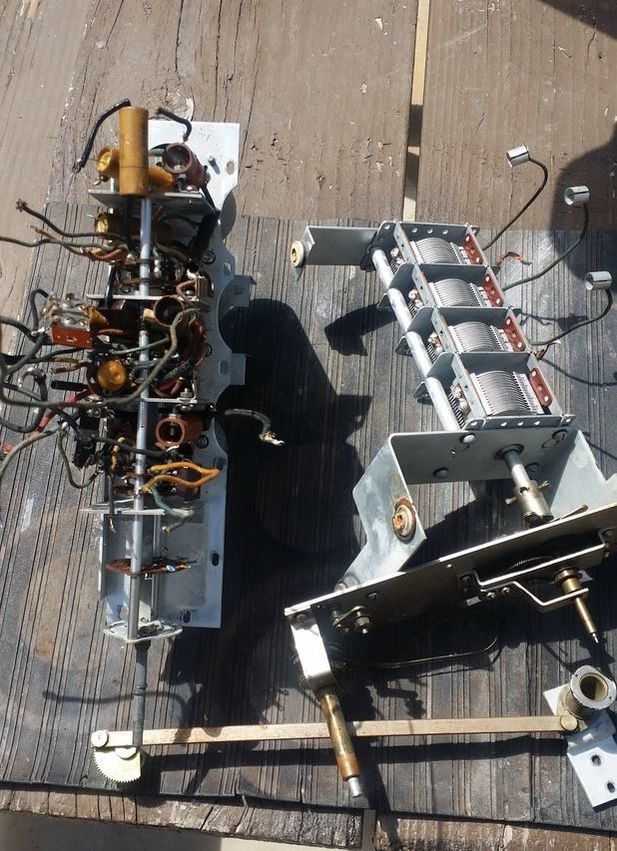
Below is the sort-of before picture. Work was started on this chassis prior to my involvement. It is shiny metal since the paint has been partially removed by wire brush. The filter caps were removed and cut open. The power/signal cable to the receiver chassis has had the connector cut off. Having done one of these before, these issues should be easy to resolve with the objective being reliable operation with an original appearance.
Below is the sort-of before picture. Work was started on this chassis prior to my involvement. It is shiny metal since the paint has been partially removed by wire brush. The filter caps were removed and cut open. The power/signal cable to the receiver chassis has had the connector cut off. Having done one of these before, these issues should be easy to resolve with the objective being reliable operation with an original appearance.
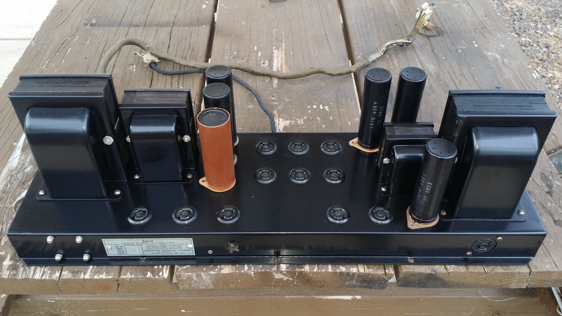
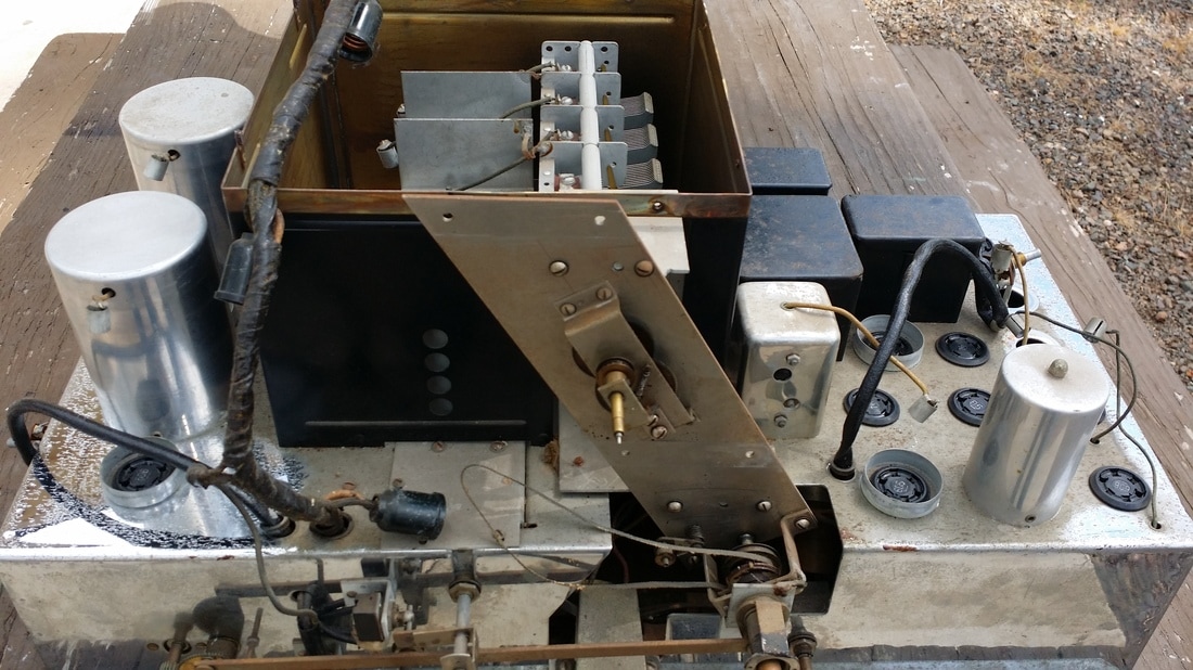
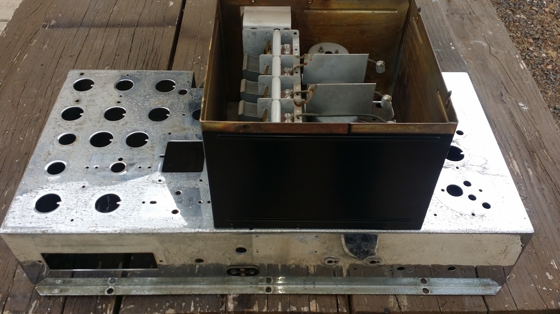
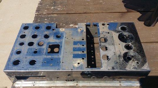
To repaint the chassis and parts correctly all of the iron (transformers/chokes) needs to be removed.
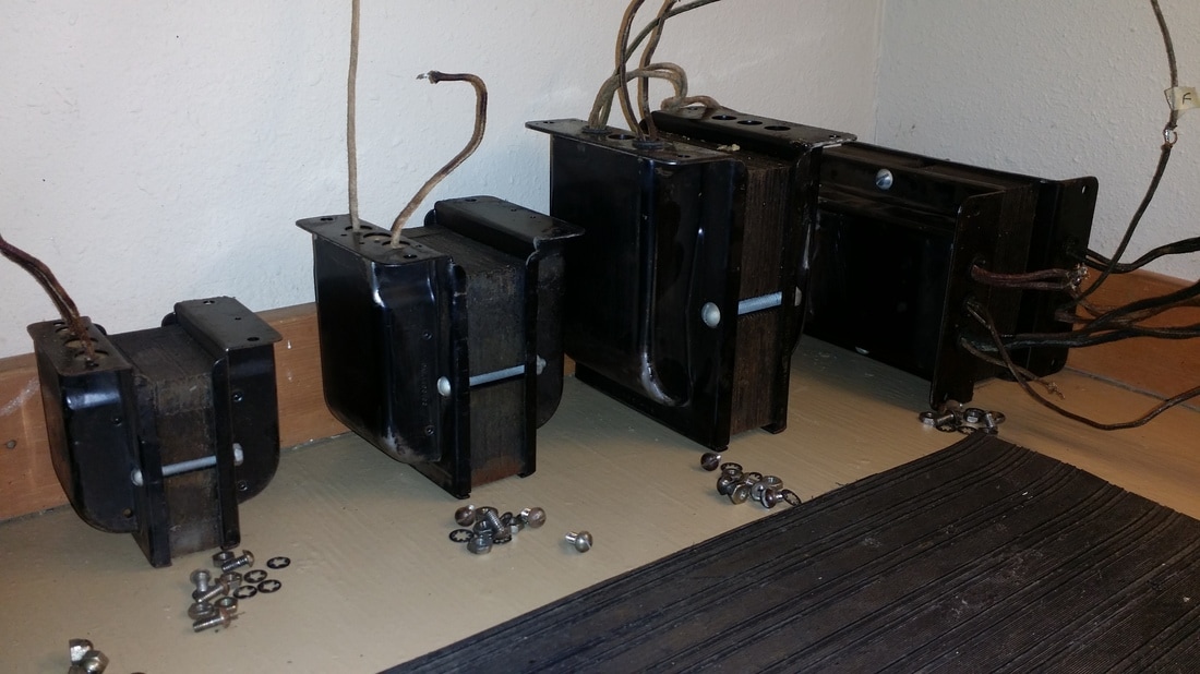
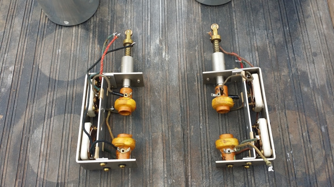
These are the two power transformers (large) and the two chokes.
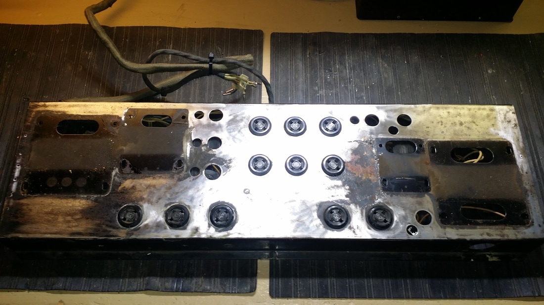
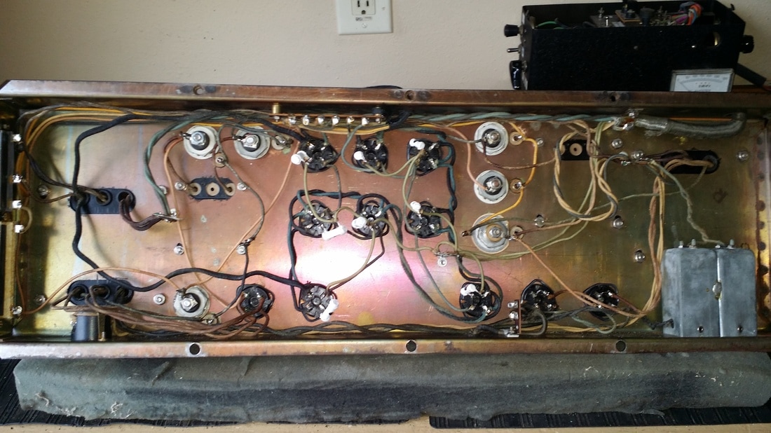
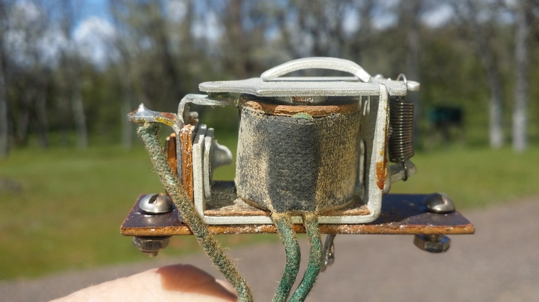
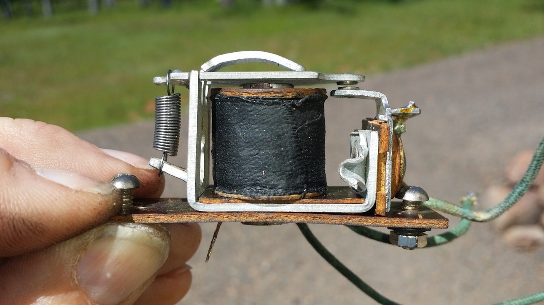
The snap rings on the tube sockets have been removed allowing the sockets to come through the top of the chassis.
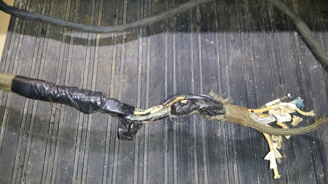
The power and signal cable going to the receiver chassis has been repaired with tape prior to being cut off of the connector. This is likely to need replacing.
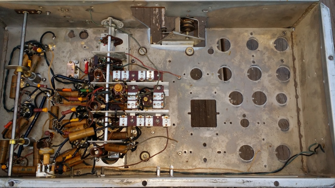
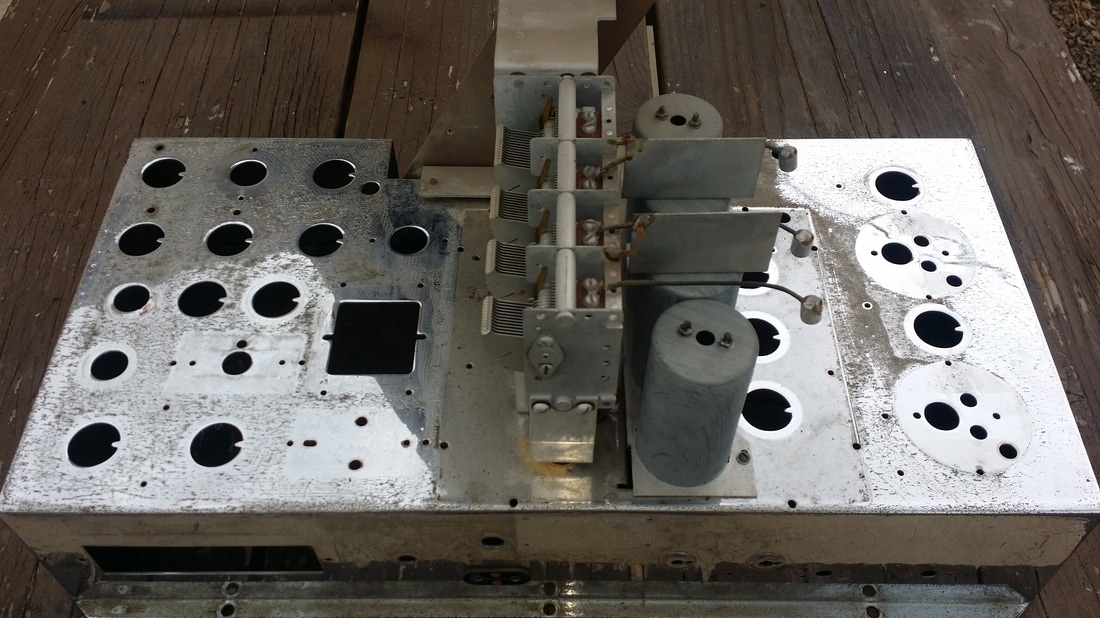
OH yes! Much better.
I am going to replace parts as needed before remounting any of the iron. It is easier to work on the chassis while it is 20lbs lighter.
I am going to replace parts as needed before remounting any of the iron. It is easier to work on the chassis while it is 20lbs lighter.
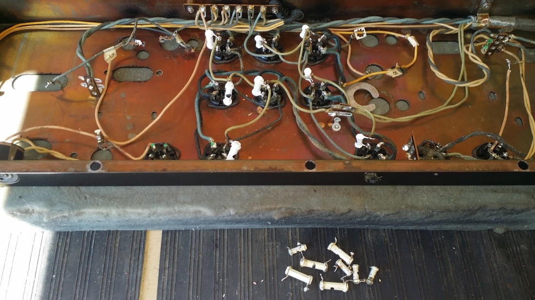
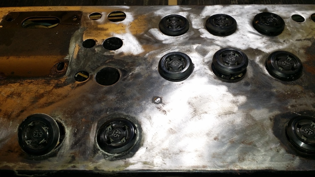
Replacement dog-bone resistors installed.
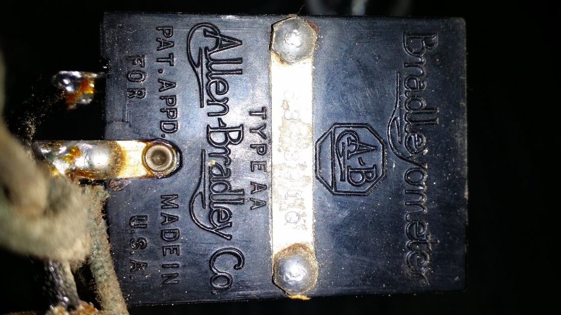
On this chassis these cathode resistors are 2 different sizes (watt rating). On the other chassis I restored they were all 1/2 watt.
It is time to start on the filter caps.
These were all early electrolytics. The design seems to be Sprague's attempt to copy and improve on the Mershon "wet" electrolytic can. There seems to be two or more versions used in the 1000Z. First, a solid copper can with a ground (-) lug incorporated into the isolated base. Then an evolution to the more common aluminum can without a ground lug. The ground lug is accommodated by an additional hole drilled in to the chassis. This extra hole is seen in all of the first 254 power/amp chassis BUT may have been deleted in some of the last 100 chassis produced. The RF/receiver chassis does not have these extra ground lug holes rather using the later version mounting system.
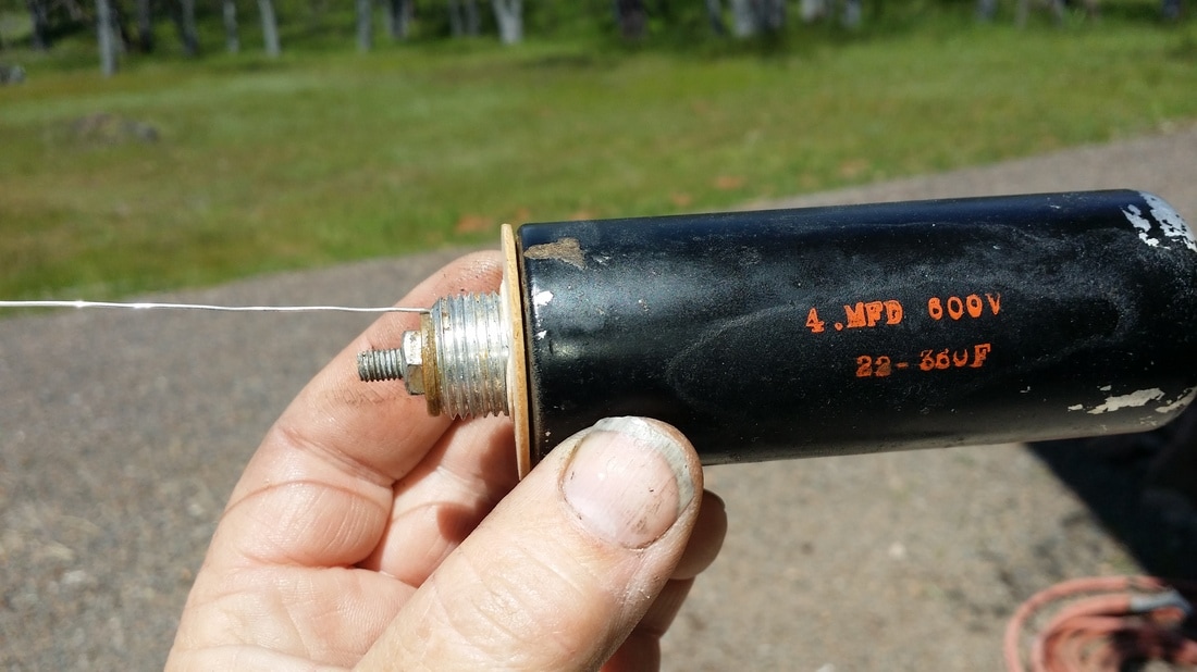
Above: The first filter.
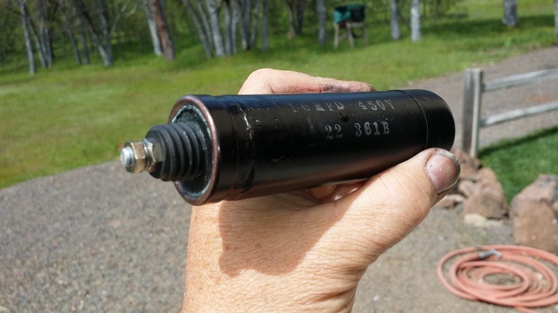
As you can see on the can, It is rated at 600V and 4uf.
The 600V rating poses a challenge for most electrolytic capacitors (even this one failed explosively). Knowing the compromises involved in using electrolytic caps in this position, I chose to use Solen metalized polypropylene instead. These, too, have some disadvantages, size being the most significant. They are, however, rated at 630 volts. I have been using these in place of electrolytics in all applications where they will fit for many years now and have not had a single failure. I anticipate a much longer life as compared to electrolytic caps especially when the electrolytic caps are being operated near their upper voltage rating. An additional advantage is not having to worry about polarity (electrolytic caps are polarized). The other significant disadvantage is cost. The Solens cost about 10 times what a 450V electrolytic cap costs.
The objective in rebuilding these cans is to exceed as much as possible the original voltage rating and to STUFF as much capacity into the can as possible - within the original spec narrowed to about -10% to +150%. So, This 4uf 600V cap is now rated for 6uf 630V (tested).
The larger value filter caps are more of a problem. They have slightly less volume since they were rated for 450V. (The volume of a can is generally larger as the uf rating or the V rating increases. In these caps the 600V rating increases the size more significantly than the lower uf rating decreases it. In other words, the 4uf @ 600V can is slightly larger than the 16uf @ 450V can).
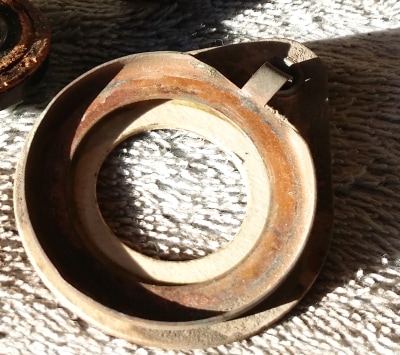
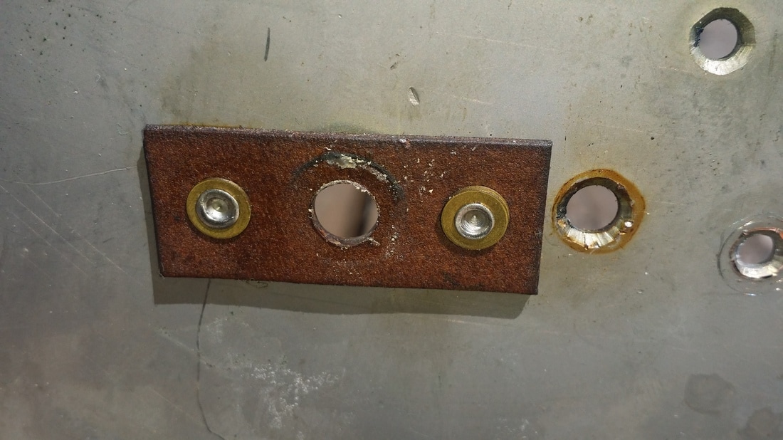
Below: the ground/lug isolation base for the early caps, showing the lead that penetrates the chassis through the 2nd hole. This configuration is not unique to early 1930s radios but this particular part with the dished edges seems unique to the 1000Z.
As you can see on the can, It is rated at 600V and 4uf.
The 600V rating poses a challenge for most electrolytic capacitors (even this one failed explosively). Knowing the compromises involved in using electrolytic caps in this position, I chose to use Solen metalized polypropylene instead. These, too, have some disadvantages, size being the most significant. They are, however, rated at 630 volts. I have been using these in place of electrolytics in all applications where they will fit for many years now and have not had a single failure. I anticipate a much longer life as compared to electrolytic caps especially when the electrolytic caps are being operated near their upper voltage rating. An additional advantage is not having to worry about polarity (electrolytic caps are polarized). The other significant disadvantage is cost. The Solens cost about 10 times what a 450V electrolytic cap costs.
The objective in rebuilding these cans is to exceed as much as possible the original voltage rating and to STUFF as much capacity into the can as possible - within the original spec narrowed to about -10% to +150%. So, This 4uf 600V cap is now rated for 6uf 630V (tested).
The larger value filter caps are more of a problem. They have slightly less volume since they were rated for 450V. (The volume of a can is generally larger as the uf rating or the V rating increases. In these caps the 600V rating increases the size more significantly than the lower uf rating decreases it. In other words, the 4uf @ 600V can is slightly larger than the 16uf @ 450V can).
Below: the ground/lug isolation base for the early caps, showing the lead that penetrates the chassis through the 2nd hole. This configuration is not unique to early 1930s radios but this particular part with the dished edges seems unique to the 1000Z.
I did not disassemble these cap cans. I would have done it slightly differently, but, working with what I had - the replacement cap is attached to the + lug with a tapped screw treated with Never Seize (RT).
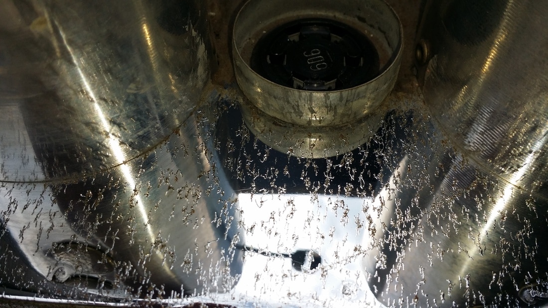
On the copper can, a ground connection is easily made to the can its self. On the Aluminum cans, I feel safest in extending a ground from within the can to the mounting hardware - not trusting an aluminum solder joint. (See picture 2 above)
On the copper can, a ground connection is easily made to the can its self. On the Aluminum cans, I feel safest in extending a ground from within the can to the mounting hardware - not trusting an aluminum solder joint. (See picture 2 above)
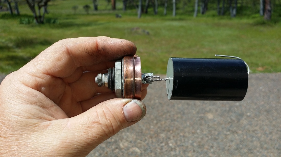
To accommodate the method in which these were disassembled, the can sections are rejoined with solder. Heat must be controlled since there is a new cap inside and excessive heating will destroy it.
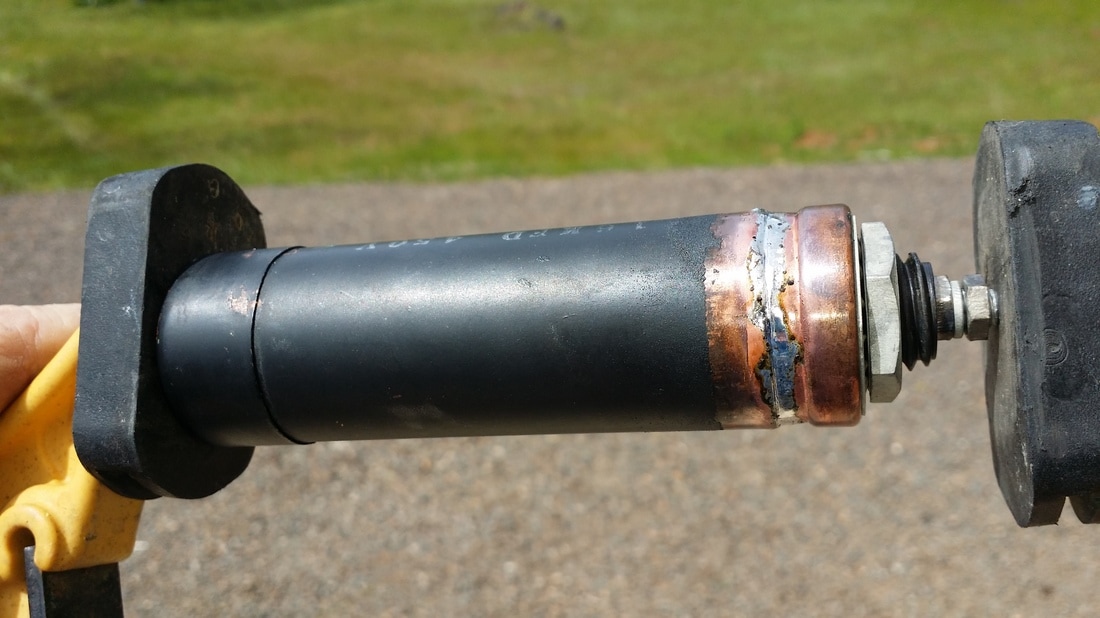
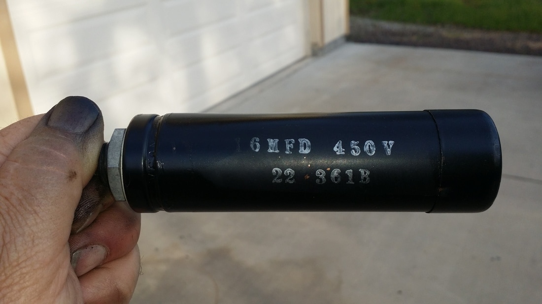
On the can below, I cleaned up the joint and plated the solder with copper. If this was the more common unpainted version it would be finished.
These caps were originally painted black. So the repair needs to be painted.
Do not paint the lower edge/crimp on the can. It needs to make electrical contact with the mounting hardware.
Do not paint the lower edge/crimp on the can. It needs to make electrical contact with the mounting hardware.
I feel, that if at all possible, the original text (value/part number) should be preserved.
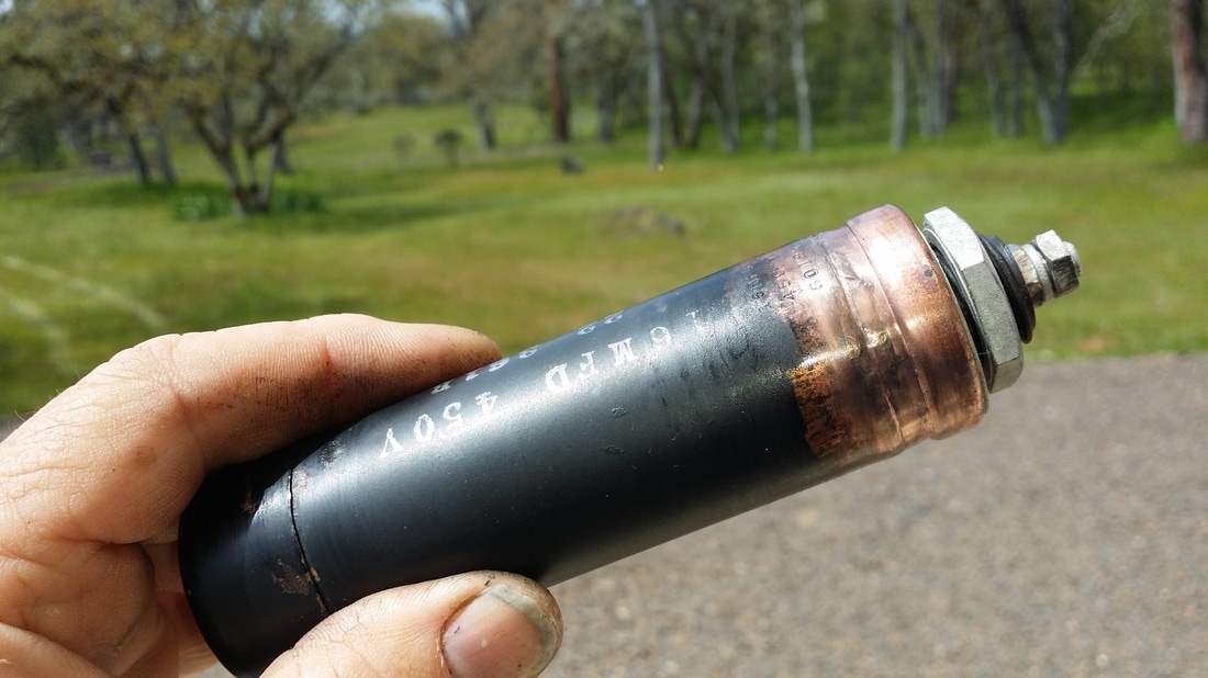
The cap above is now rated for 20uf @ 630V.
Yeah, I painted my thumb too. Nice! ;-)
Yeah, I painted my thumb too. Nice! ;-)
With all of the parts rebuilt, tested, disassembled, painted and reassembled I was able to put the amp back together.
I have decided to rebuild the cable that links the two chassis rather than risk it shorting out.
I have decided to rebuild the cable that links the two chassis rather than risk it shorting out.

 RSS Feed