
So were should I start? Well, this is more about finishing but the story starts over a year ago.
Let's see, find one of the most valuable radios and take it apart, all apart, every component, every wire. Then take the components apart. But don't forget, you have to put it back together again. Not so that it looks like it has not been apart. No, that is going to be obvious. But back together so that it looks like today is 1936 - no, even belter, like it is 1936 with none of the frail parts.
Why would you do this? That's easy. Anything less is just not going to work. Even more important, anything less is going to leave a valuable piece of history in a precarious position. It had to be done. It wasn't going to survive without an investment. It could have been parted out for a profit. It could have been "restored" with considerably less effort, then sold. Either of those options would be OK for another radio but not this one. No, it had to be preserved as true to its original form as possible and in a way that no one would consider anything less than keeping it intact. Besides, I like a challenge.
So, if it had been perfect or even good we would not be having this conversation. Yeah, I know that I am doing all the talking but I have heard all of the comments. Restuffing caps, casting new resistors, new wire, "Why put that kind of effort into any but the rarest radio?" Well, when the right radio comes along it helps to have some experience. Even so, this one was going to require tools, techniques and time like none before.
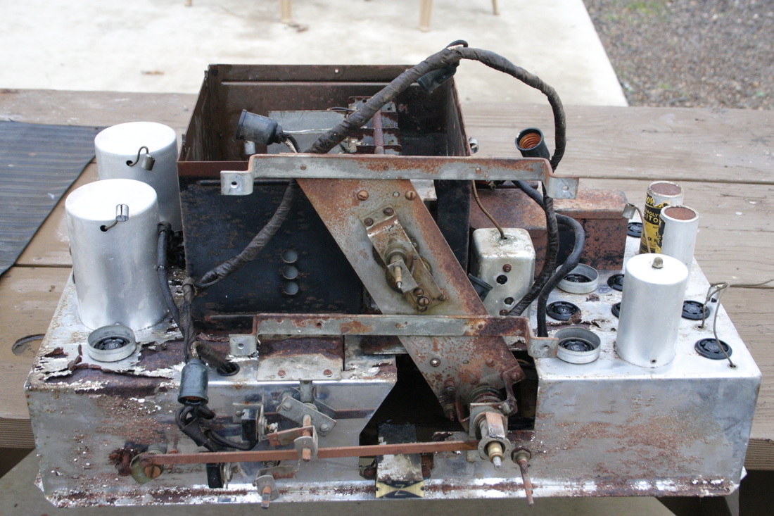
Let's examine the basket:
Let's see, find one of the most valuable radios and take it apart, all apart, every component, every wire. Then take the components apart. But don't forget, you have to put it back together again. Not so that it looks like it has not been apart. No, that is going to be obvious. But back together so that it looks like today is 1936 - no, even belter, like it is 1936 with none of the frail parts.
Why would you do this? That's easy. Anything less is just not going to work. Even more important, anything less is going to leave a valuable piece of history in a precarious position. It had to be done. It wasn't going to survive without an investment. It could have been parted out for a profit. It could have been "restored" with considerably less effort, then sold. Either of those options would be OK for another radio but not this one. No, it had to be preserved as true to its original form as possible and in a way that no one would consider anything less than keeping it intact. Besides, I like a challenge.
So, if it had been perfect or even good we would not be having this conversation. Yeah, I know that I am doing all the talking but I have heard all of the comments. Restuffing caps, casting new resistors, new wire, "Why put that kind of effort into any but the rarest radio?" Well, when the right radio comes along it helps to have some experience. Even so, this one was going to require tools, techniques and time like none before.
Let's examine the basket:
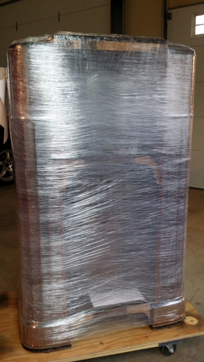
I have to thank my friend Harry for wrapping it up like a ham sandwich.
We unloaded it onto that rolling dolly where it was to reside for over a year. Heavy radio! Even the 2 chassis are heavy.
We unloaded it onto that rolling dolly where it was to reside for over a year. Heavy radio! Even the 2 chassis are heavy.
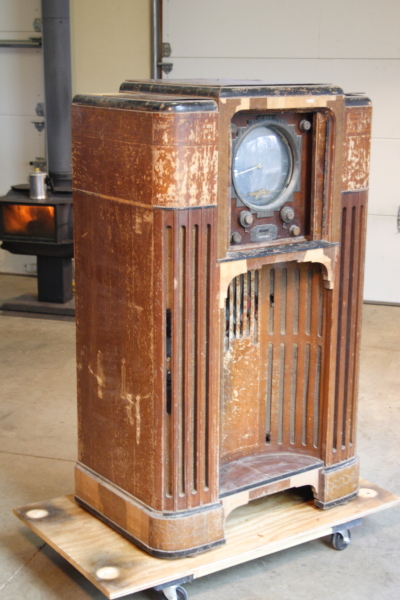
It certainly wasn't in the best shape nor in the worst shape for an "as found" 1000Z. It was actually amazingly intact yet there was no part if it that did not require attention.
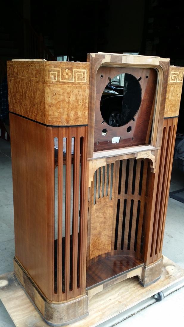
Even prior to disassembly I began to order the veneers for the cabinet restoration. It was missing a lot of the Laurel that made up the dark trim and base. Even in good shape this stuff is brittle and hard to work. 85 years had left very little of the original in salvageable shape. So was it "West Indian" or Australian? Ordering the more exotic veneers can be a real challenge.
It was also going to need walnut for the top. Just avoid the cheap purple-looking stuff with a lot of sap-wood. Less of a challenge than the Laurel.
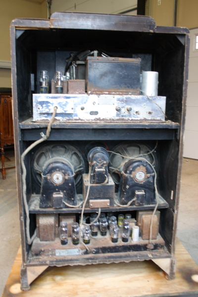
Yeah, it was a little dusty - or was that rusty? Well, as is usually the story, there was some of each. But look at all of those 45s! To bad none of them were Zenith Brand, something I require for this kind of restoration and the last thing I am STILL looking for. I'm still short 2 Zenith "engraved" 45s and 3 5Z3s.
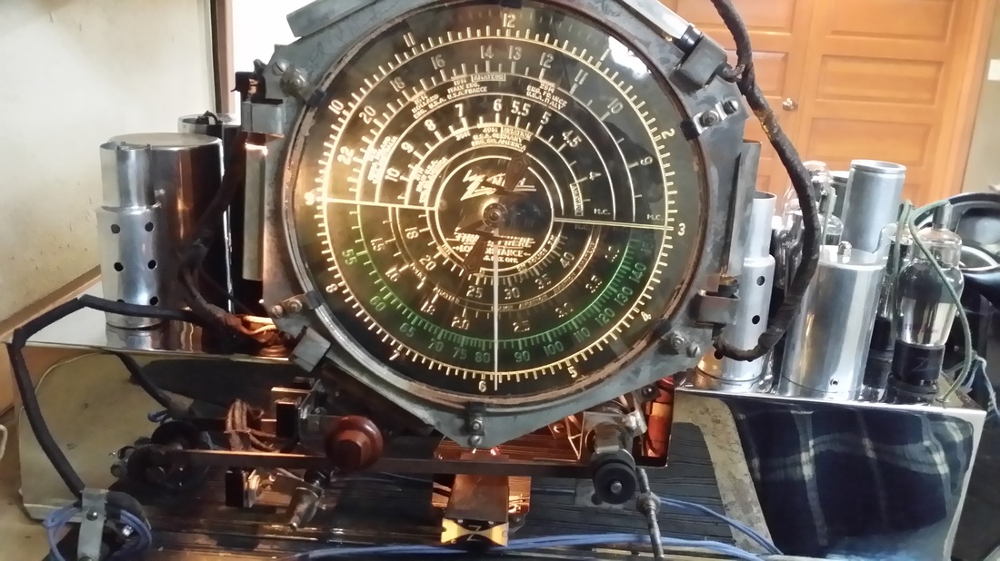
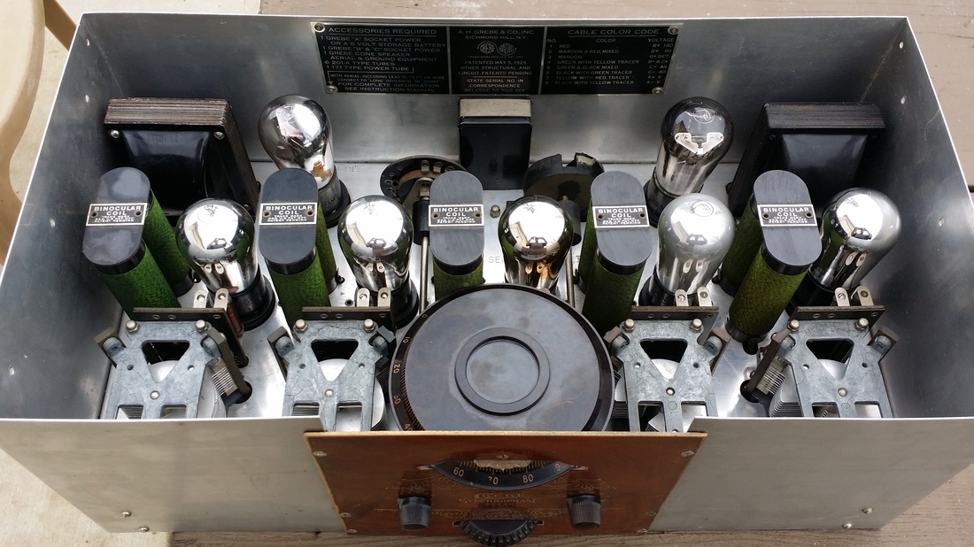
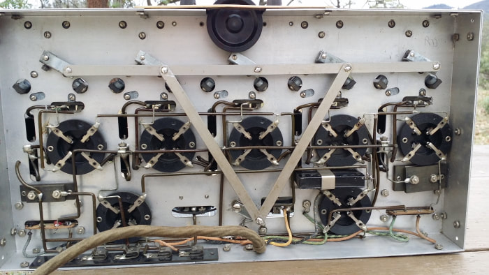
Twenty five tubes with 23 of them doing something in most settings, 24 of them used on the broadcast band and 24 of them used on the upper SW frequencies, but almost no case where all 25 would be used. But more on that later.
This is a second run model with the tweeter and local distance switches and a upper frequency band limited to about 45mhz, give or take how the oscillator feels about running on that 5th band. The schematic and very little else is located in Riders Vol. 10.
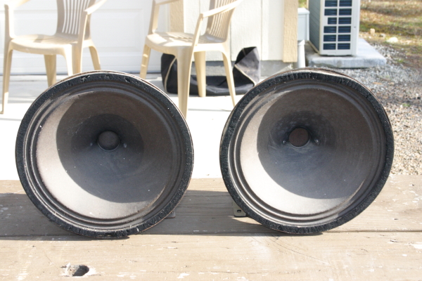
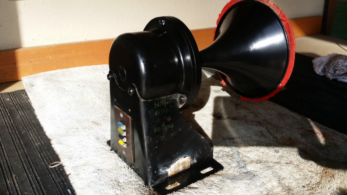
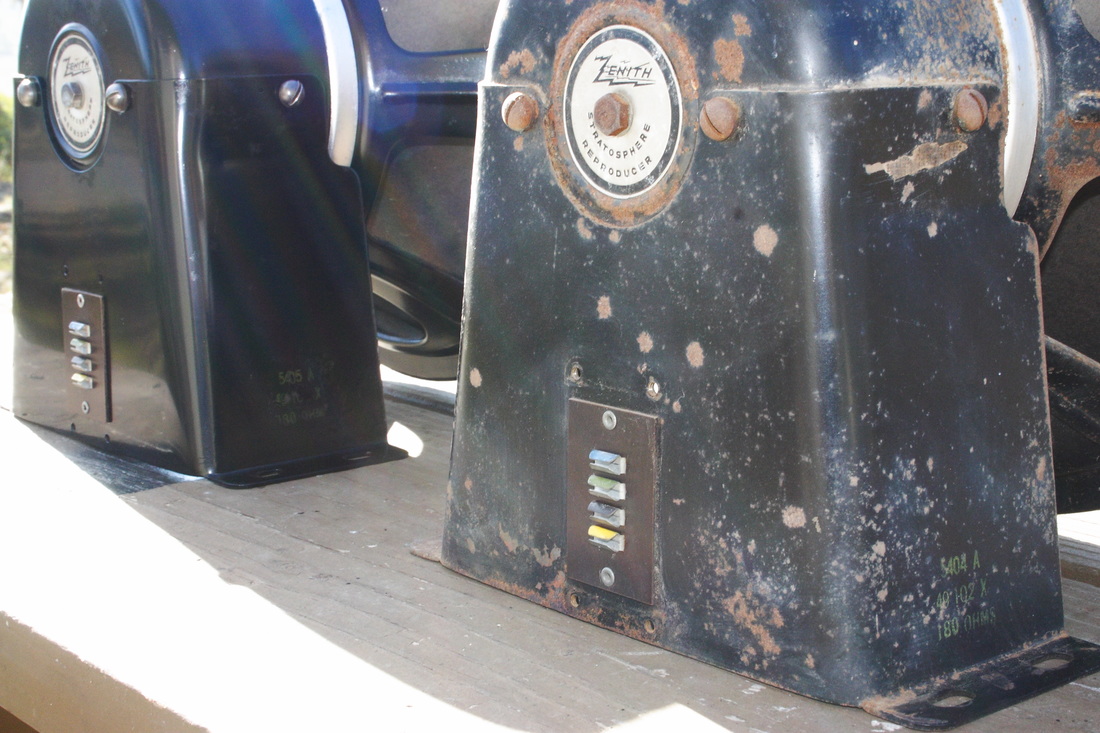
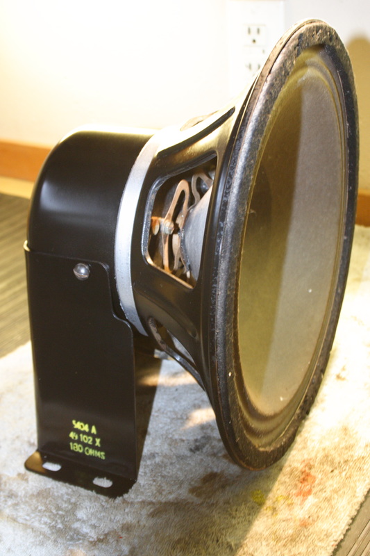
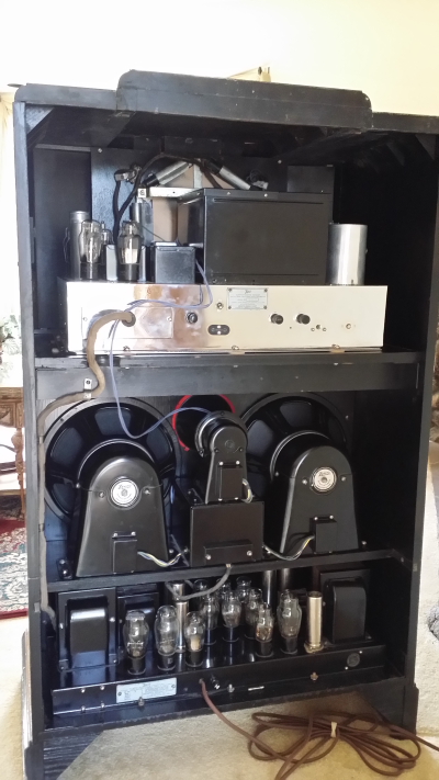
Luckily, all 3 speakers were there and intact, especially the super-rare and very impressive tweeter. Look at the cones on those woofers! That is going to produce some serious base! At least I wasn't going to have those reconed - or so I thought. Note to self: Eight 45s running in Push-pull, parallel is a LOT of power!
So I started cleaning up the cabinet and while waiting., I started working from the middle, out. The crossover/audio OP transformer assembly was first. BUT the schematic doesn't even give values for the caps. just a "special order" part number.
So I started cleaning up the cabinet and while waiting., I started working from the middle, out. The crossover/audio OP transformer assembly was first. BUT the schematic doesn't even give values for the caps. just a "special order" part number.
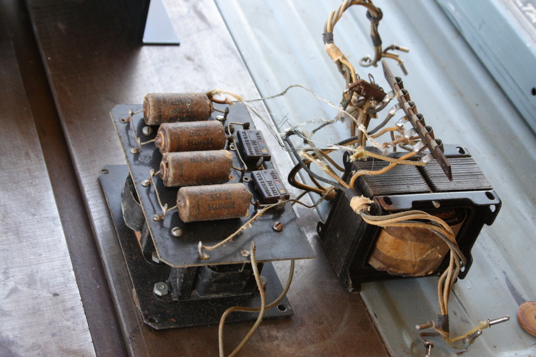
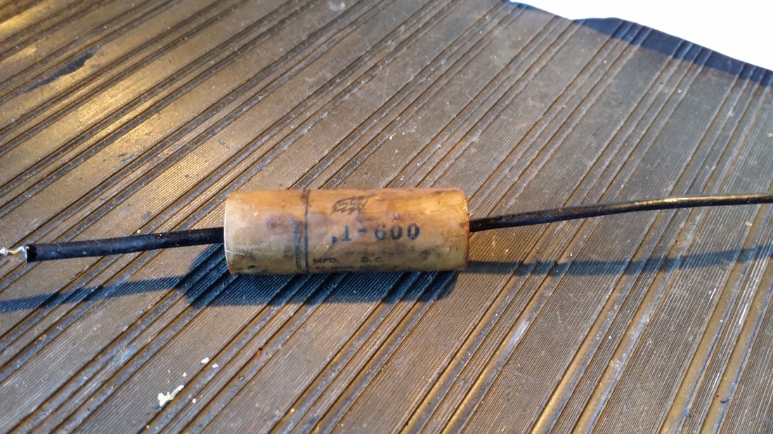
"Caps on a Stick", or so I call the 1935 versions rolled, paper and foil on a real stick. These are a little tough to rebuild and rated at 1000Votlts DC. No wonder they were special order! The two caps that look like micas are also paper, rated at 1000V (in series). Observe the carcasses in the lower right and the rebuilt/recast parts installed on the board. OP Transformer tests good!
It was a good start.
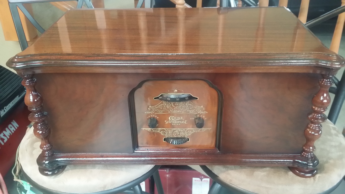
At this point, let me inject a observation. As I mentioned, this project is finished. I have been spending a lot of time playing the radio, listening to shortwave broadcasts and playing MP3s through the "Phono" jack, which has a switch on the back of the chassis to select. That is until I put the fancy screened back on and pushed the radio up against the wall.
So, where was the Zenith QC guy in 1935? If you put the back on, you cant get to the phono/radio switch. And, if you put the radio against the wall, you can't get the back off. So the back lies against the wall behind the radio so I can use the port. Could this be the reason that some of the backs were lost? BTW, the sound from the Strat/MP3 is great, the kind of high fidelity not found again until radios made in the late 1950s.
As a tech note, I am using a center tapped ~3 to 1 transformer to isolate, combine R and L channels and step up the voltage form my phone to the phono input. Works great.
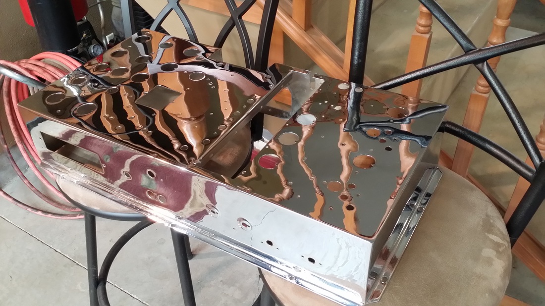
On to the power amp/ supply, a copper plated, 11 tube, split supply incorporating eight 45 tubes arranged in a parallel - push - pull configuration and three 5Z3s for B+ from two power transformers. The 5Z3s are run as a pair and a single on the B+ and "screen" supply, though the "screen supply" is the B+ for the 4 tubes running the shadow meter, AVC and Q AVC circuits. (White leads on the radio chassis)
At this point, let me inject a observation. As I mentioned, this project is finished. I have been spending a lot of time playing the radio, listening to shortwave broadcasts and playing MP3s through the "Phono" jack, which has a switch on the back of the chassis to select. That is until I put the fancy screened back on and pushed the radio up against the wall.
So, where was the Zenith QC guy in 1935? If you put the back on, you cant get to the phono/radio switch. And, if you put the radio against the wall, you can't get the back off. So the back lies against the wall behind the radio so I can use the port. Could this be the reason that some of the backs were lost? BTW, the sound from the Strat/MP3 is great, the kind of high fidelity not found again until radios made in the late 1950s.
As a tech note, I am using a center tapped ~3 to 1 transformer to isolate, combine R and L channels and step up the voltage form my phone to the phono input. Works great.
On to the power amp/ supply, a copper plated, 11 tube, split supply incorporating eight 45 tubes arranged in a parallel - push - pull configuration and three 5Z3s for B+ from two power transformers. The 5Z3s are run as a pair and a single on the B+ and "screen" supply, though the "screen supply" is the B+ for the 4 tubes running the shadow meter, AVC and Q AVC circuits. (White leads on the radio chassis)
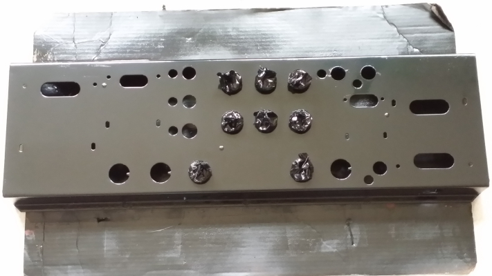
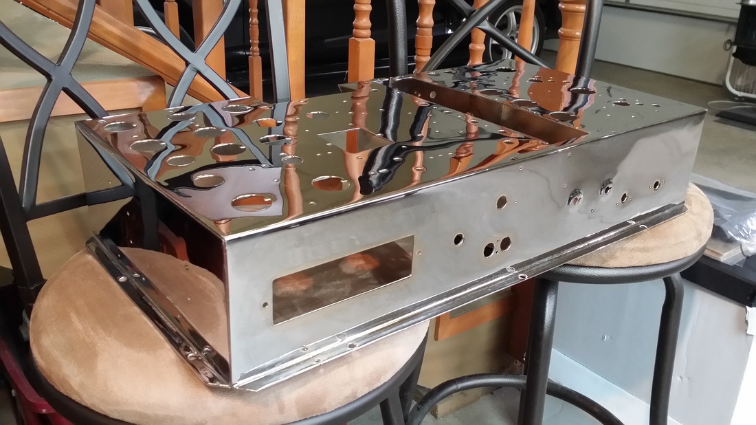
Pictures of the chassis stripped for painting. I used a gloss level between gloss and semi-gloss. It seemed to be a good match to the original.
Even though it did not look so good in the original photo, the chassis was mostly just dirty. Since I had to repaint most of the other black components, I did not want to have a color/gloss mismatch here so it was repainted.
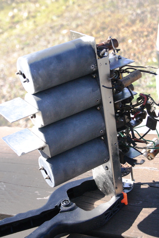
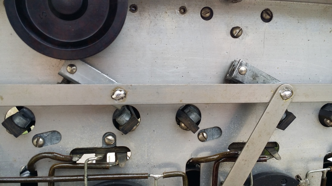
Now, in these pictures I would like you to pay attention to the 6 pairs of holes for the filter caps. The term PAIRS is critical here.
As with every Strat power chassis I have seen the original filters were replace at least once before. This one was no exception. The tech did something a little unexpected in this case, something that was a real gift to me, but maybe a shortcut for him at the time. He left the original ground contacts/cups in place.
Even though it did not look so good in the original photo, the chassis was mostly just dirty. Since I had to repaint most of the other black components, I did not want to have a color/gloss mismatch here so it was repainted.
Now, in these pictures I would like you to pay attention to the 6 pairs of holes for the filter caps. The term PAIRS is critical here.
As with every Strat power chassis I have seen the original filters were replace at least once before. This one was no exception. The tech did something a little unexpected in this case, something that was a real gift to me, but maybe a shortcut for him at the time. He left the original ground contacts/cups in place.
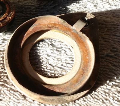
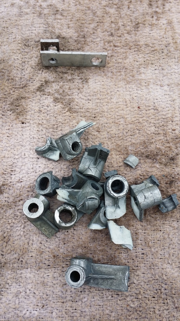
Filter cap mounting cup/ground and insulator as found.
Sorry if this is a little dry, but I put a lot of thought and time into this aspect of the rebuild.
First, it should be known that Zenith purchased the other specially built caps used in the Stratosphere from Sprague (See those in the crossover above and more on the receiver chassis later).
The Mershon company was building a very similar and successful electrolytic capacitor design used in many radios of the late 1920s - 1930. This was the familiar copper, liquid filled electrolytic cap found in Crosley, Philco and other brands of the time. The Mershon Co was purchased in 1930 by Magnavox. It seems that Sprague adopted this design in an almost identical product with the addition of a nickel plating on the copper can. Sprague was also challenged regarding the Mershon patents.
https://en.wikipedia.org/wiki/Ralph_D._Mershon
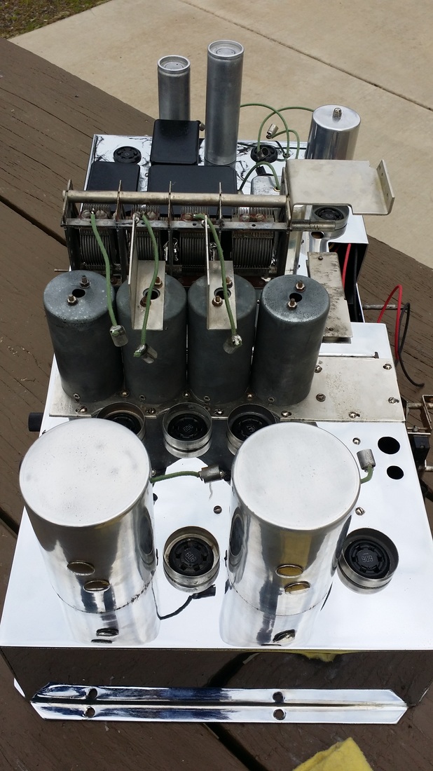
Since Mershon was gone by 1934 and the other very unique caps in this unit were manufactured by Sprague AND Sprague was the other manufacture using this design incorporating the ground lug. And the chassis is drilled for these very unique ground lugs/mounts. AND my chassis has the mounts still in place - - It seemed that a Sprague electrolytic cap of the Mershon design was the only reasonable candidate for an original replacement. Besides, they are polished nickel and very cool. A somewhat hard to find Sprague cap, in at least 3 uf values was being used with a similar base at the time. It was my conclusion that I needed 6 of them in 2 different uf values to build replacements for the Strat power amp chassis. As far as I know, this is the first restoration to use these caps.
Sorry if this is a little dry, but I put a lot of thought and time into this aspect of the rebuild.
First, it should be known that Zenith purchased the other specially built caps used in the Stratosphere from Sprague (See those in the crossover above and more on the receiver chassis later).
The Mershon company was building a very similar and successful electrolytic capacitor design used in many radios of the late 1920s - 1930. This was the familiar copper, liquid filled electrolytic cap found in Crosley, Philco and other brands of the time. The Mershon Co was purchased in 1930 by Magnavox. It seems that Sprague adopted this design in an almost identical product with the addition of a nickel plating on the copper can. Sprague was also challenged regarding the Mershon patents.
https://en.wikipedia.org/wiki/Ralph_D._Mershon
Since Mershon was gone by 1934 and the other very unique caps in this unit were manufactured by Sprague AND Sprague was the other manufacture using this design incorporating the ground lug. And the chassis is drilled for these very unique ground lugs/mounts. AND my chassis has the mounts still in place - - It seemed that a Sprague electrolytic cap of the Mershon design was the only reasonable candidate for an original replacement. Besides, they are polished nickel and very cool. A somewhat hard to find Sprague cap, in at least 3 uf values was being used with a similar base at the time. It was my conclusion that I needed 6 of them in 2 different uf values to build replacements for the Strat power amp chassis. As far as I know, this is the first restoration to use these caps.
Finished chassis showing Sprague filters/mounts.
The filters were rebuilt using 630 volt film caps at, or slightly above, the factory rated capacitance. The caps are metalized polypropylene manufactured by Solen , stacked to achieve the desired values.
By this point the receiver chassis had been stripped of parts and was off to the chrome shop for a very long, aggravating, rechroming.
Here is a picture of the resistor "kit" that I prepared for the project. All of the carbon resistors except 2 very unique specimens that were still in spec, were replaced. The lower resistance units were replaced with wire wound resistors at 3W or more. None of the replacements incorporated modern resistors of less than 2 W. All were cast into the "dog bone" shape and painted.
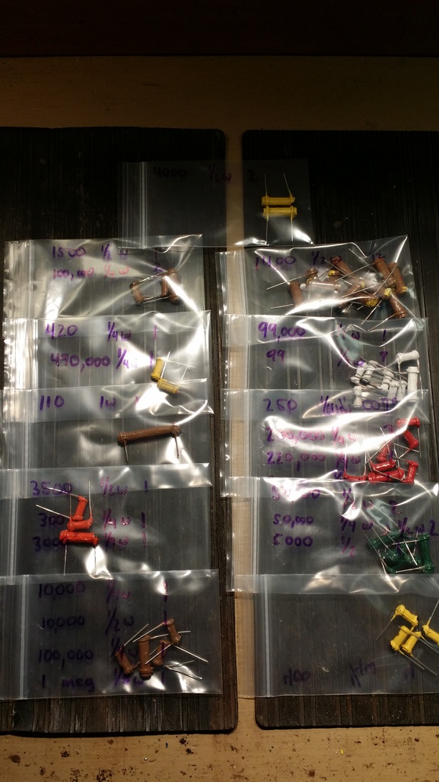
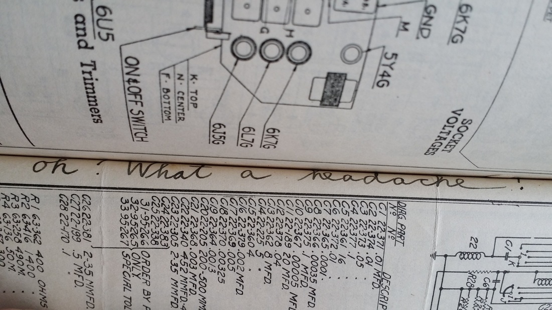
For those of you considering a restoration, or just servicing a 1000Z, here is a note from the margin of my Riders Manual:
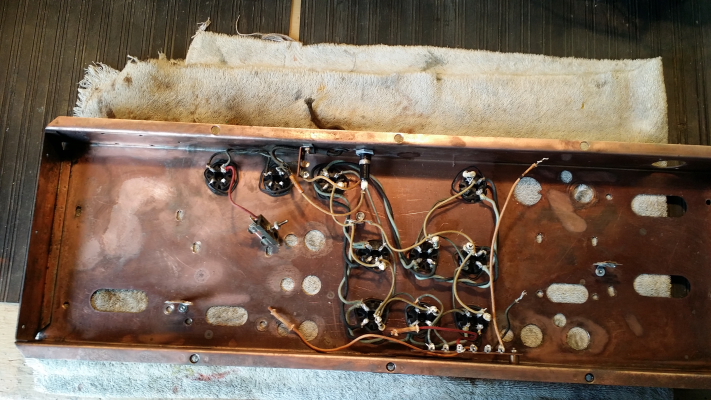
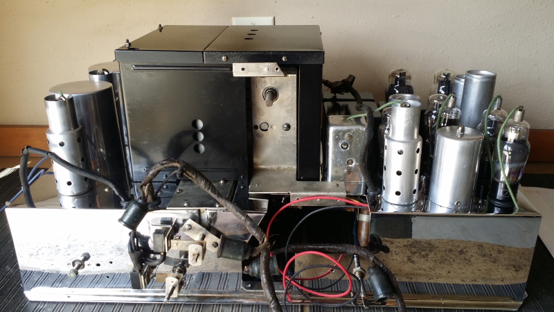
Below: Receiver chassis prior to tear-down:
Sub assemblies would be bagged and tagged prior to rebuilding them. All of the metal parts were derusted and replated, mostly in nickel here at the shop rather than sending them out.
From the beginning I could see that one of the challenges would be determining the original wire color since every wire now was either black or yellow. I was going to eventually replace about 95% of the original wiring. Some special applications like the gimmick capacitor were retained for originality. In some cases the colors were known such as the green/black combination for the filaments. In other cases the color of the control/power cable was a help since the colors were specified on the schematic. Sometimes a wire could be trimmed back with a razor to find the original color. It appears that Zenith did try to stick with a color for a particular application like B+ or screen voltage. But I am getting ahead of myself.
Another challenge at this stage of the process was to preserve or recreate original part numbers and other markings.
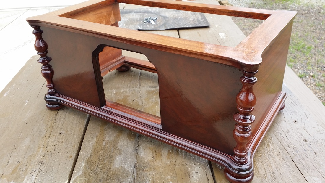
THE VENEER IS HERE!
As I mentioned before, the laurel is a particularly nasty wood to work with. It is brittle, hard to trim and cut and wants to split down the grain. It needed to be book matched end to end to end in about 6 inch sections and be a mirror image on the opposite side of the base.. No problem, only don't forget to add the inlay near the top.
 | 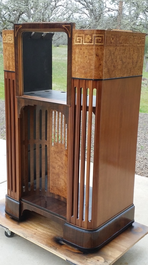 |
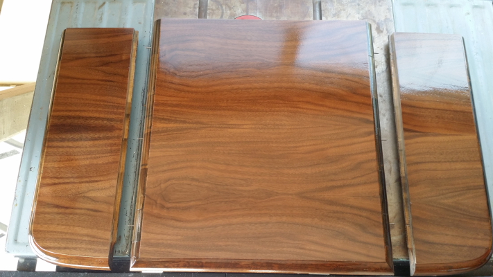
The top needed new book matched walnut, continuous across the 2 levels (three sections).
Now the sliding doors can be a little bit of a challenge, or, a really big problem.
Have you noticed that there are no handles - anywhere? Prying them apart with your fingers (or a screwdriver) is always possible. But if they do not fit perfectly and slide smoothly, getting them closed is nearly impossible. They have to slide easily enough that they can be closed, with no gaps, just by dragging your fingers across their surface. I'll bet a lot of these were opened and stayed that way. In this case, the disassembly allowed for fine-tuning the doors which slide on small felts, new ones in this case., in groves above and below.
Have you noticed that there are no handles - anywhere? Prying them apart with your fingers (or a screwdriver) is always possible. But if they do not fit perfectly and slide smoothly, getting them closed is nearly impossible. They have to slide easily enough that they can be closed, with no gaps, just by dragging your fingers across their surface. I'll bet a lot of these were opened and stayed that way. In this case, the disassembly allowed for fine-tuning the doors which slide on small felts, new ones in this case., in groves above and below.
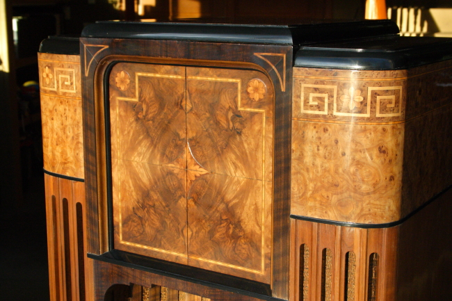
Nice grain pattern. Note that the two ornamental flowers and the central embellishment are not inlayed, rather affixed on top of the door veneer.. It does give your fingers something to push on to close the doors. The trim around the edge is inlayed.
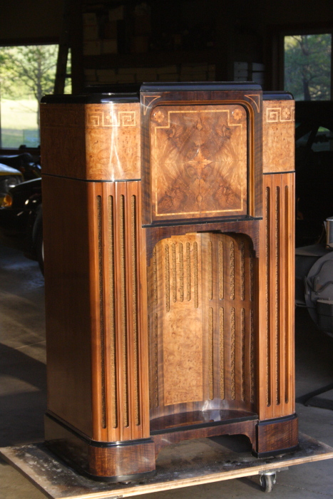
The grill cloth available today has the right pattern but is way too gold. It had to be dyed to a more reddish - brown color.
At this point the upper chassis is still off at the plater's. He is in no rush to finish it and is annoyed by requests for a completion date - great!
But there are a lot of parts to work on and as I mentioned, this inspired me to set up my own plating shop. I can do nickel, copper (acid), and bronze. Bronze! - Did you know that Zenith bronzed the wooden knobs on the Strat. yeah, like baby shoes? And then painted them (too). I'll bet somebody had the great idea to plate the knobs and then didn't like the result so they covered most of the plating with dark brown paint, but that is just a guess.
Finding the correct springs for the shafts on the variable IFs was a challenge. The old springs were broken. The assembly will return to the narrow (IF) position mostly by gravity, the spring helps make sure. If to large of a spring is used the mechanism binds. You don't want to break anything you can't make.
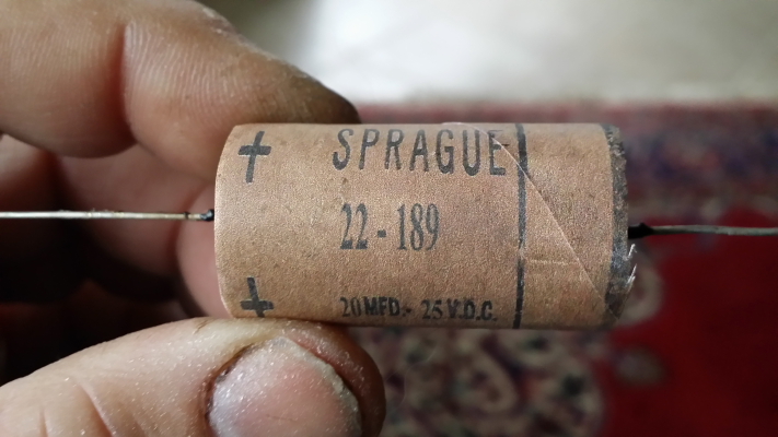
Here was another challenge. Along with the filter caps, the other electrolytics in the receiver were missing. These were low voltage, 20 uf at 25V and were on the cathode of the 76 (tube) audio stages. They were bypassed with a resistor.
These would not have been "wet" caps. No, they would have been "dry" electrolytics that had been in use for several years at this point. The earliest ones were "caps in a box". These boxes were usually large and mounted to the chassis with screws. Keep in mind that there were 3 of these (one slightly smaller). Could they have put them in one large box? How about 3 smaller boxes? No. I could not find a place that either could have been mounted and Zenith would not have left them floating around in the chassis.
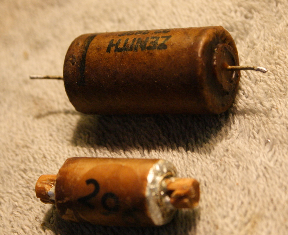
So I decided what must have been used was the new(er) tubular dry electrolytic which was smaller and could be installed like the paper caps (though some had mounting clamps). Sprague was making such a device around this time. I went to my collection of thousands of vintage caps and found a likely specimen. (yes, that is why I have thousands of old caps).
Now, the paper caps in the receiver were all marked Sprague, not Zenith (as in the crossover) but they did have the Zenith part number on them. So making a long story short, I borrowed the artwork off of the Sprague dry electrolytic, added the Zenith part number and sized it to match the tubes I had for the replacement caps. A little glue and - what you see above. This is more of an "artist's concept" of what the cap was likely to have looked like, but a lot better than hanging a bare Nichicon in its place. These are rated at the capacitance spec. and 160V.
These would not have been "wet" caps. No, they would have been "dry" electrolytics that had been in use for several years at this point. The earliest ones were "caps in a box". These boxes were usually large and mounted to the chassis with screws. Keep in mind that there were 3 of these (one slightly smaller). Could they have put them in one large box? How about 3 smaller boxes? No. I could not find a place that either could have been mounted and Zenith would not have left them floating around in the chassis.
So I decided what must have been used was the new(er) tubular dry electrolytic which was smaller and could be installed like the paper caps (though some had mounting clamps). Sprague was making such a device around this time. I went to my collection of thousands of vintage caps and found a likely specimen. (yes, that is why I have thousands of old caps).
Now, the paper caps in the receiver were all marked Sprague, not Zenith (as in the crossover) but they did have the Zenith part number on them. So making a long story short, I borrowed the artwork off of the Sprague dry electrolytic, added the Zenith part number and sized it to match the tubes I had for the replacement caps. A little glue and - what you see above. This is more of an "artist's concept" of what the cap was likely to have looked like, but a lot better than hanging a bare Nichicon in its place. These are rated at the capacitance spec. and 160V.
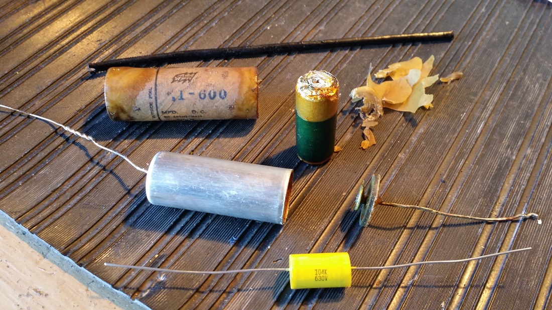
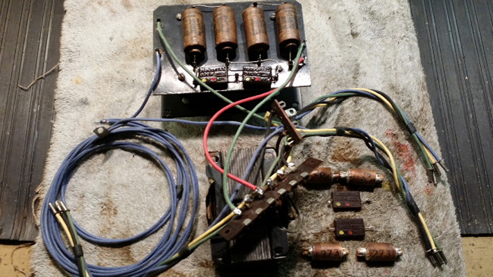
Above is a picture of the caps found in the receiver chassis plus a .5uf version of one of the stick caps. Missing from the picture is the second paper barrel found inside of all of the caps. These are built very much like late paper-in-oil caps only there is no oil. The leads are actually soldered to the endcaps as they pass through an eyelet. It looks like they were trying to build a more reliable cap with much better seals.
In the reconstruction I splice on heavier, longer leads inside of the metal tube and then those are soldered to the endcaps as in the original giving the cap the heavier gauge leads like the original. Some of these were damaged or badly stained so I recreated the artwork for the paper caps as well.
In the reconstruction I splice on heavier, longer leads inside of the metal tube and then those are soldered to the endcaps as in the original giving the cap the heavier gauge leads like the original. Some of these were damaged or badly stained so I recreated the artwork for the paper caps as well.
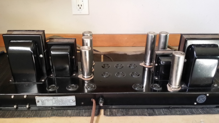
"I don't care if it is not finished, I am coming to get it!"
And, what do you know, all of a sudden the chassis was finished!
I remember in the old days I could take a beat up old part into Portland Chrome and in a week get back something that looked brand new. Those days are gone.
I remember in the old days I could take a beat up old part into Portland Chrome and in a week get back something that looked brand new. Those days are gone.

Well it probably looks as good or better than it ever did.
Now where do all of those parts go - not to mention all of those black and yellow wires?
Now where do all of those parts go - not to mention all of those black and yellow wires?
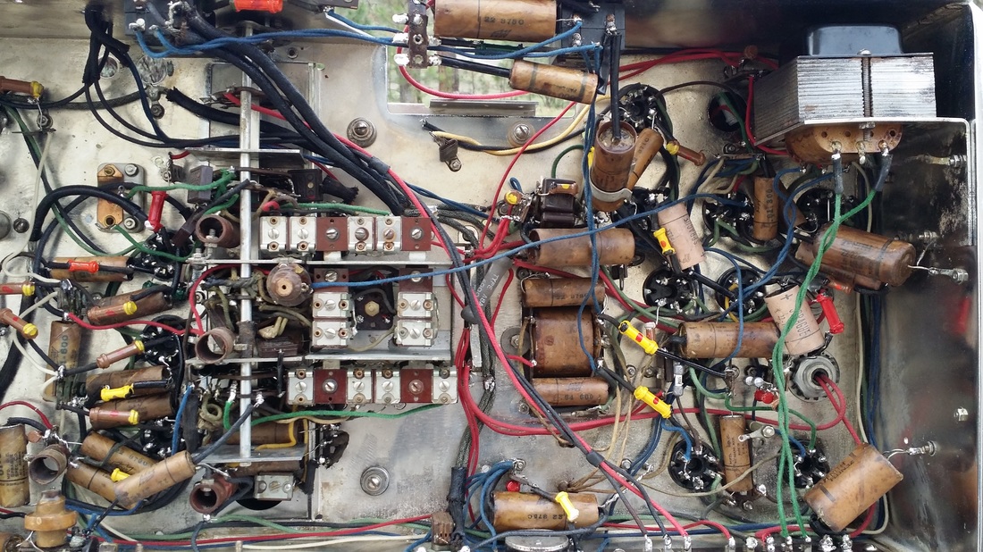
Oh yeah, now I remember!
There is still one foreign part near the center. One 5K ohm section of the cannedohm was bad. Maybe one day I'll find one or try to make one - 10K, 5K and 5K. Finding the wire for the 10K section seems to be the problem.
There is still one foreign part near the center. One 5K ohm section of the cannedohm was bad. Maybe one day I'll find one or try to make one - 10K, 5K and 5K. Finding the wire for the 10K section seems to be the problem.
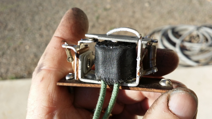
One of the more interesting items top-side of the chassis is this relay, which had an open winding. I remember briefly glancing at the schematics as I was pulling items off of the chassis. It is part of the "Q AVC" circuit. it is basically the third of 3 tubes on the AVC, 4 if you count the tube driving the shadow meter. These get a voltage From an extra winding in the 3rd IF transformer. This signal is amplified by the first 6D6 and delivered to the AVC tube and through a variable to the twin triode 85 tube that is the Q AVC. At a voltage above ~ neg 2V (more positive or closer to 0 )both triodes, in parallel, close the relay which is across the output of the interstage transformer and mutes the audio - it is a squelch circuit. A strong signal opens the relay.
The AVC its self works well. it needs to. If you tune from a weak station to a strong station without it, bad things can happen. Fortunately the AVC is always on, unlike the selectable Q AVC.
At this point I should mention that during one of these transients from low to LOUD I started hearing a buzz from one of the woofers. It got worse. Soon pieces of paper were flying as well as a lot of dust. Eventually both woofers succumbed to the AWSOME power of the amp.
Really, the paper looked good but was as crispy as old newsprint. I am glad I found this out while testing rather than after it was all put back together..
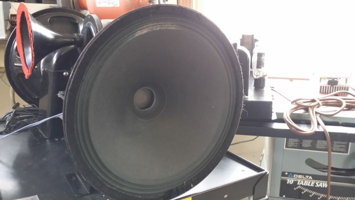
New cones done here at the shop.

Yeah, I had to borrow a knob and that big grommet. After a while my fingers were getting tired. Seems like about 100 turns end to end.

Alignment take a lot of bench space. The power supply/amp is out of the picture on the right.
It would be nice if the broadcast padder was accessible from the bottom.
It would be nice if the broadcast padder was accessible from the bottom.
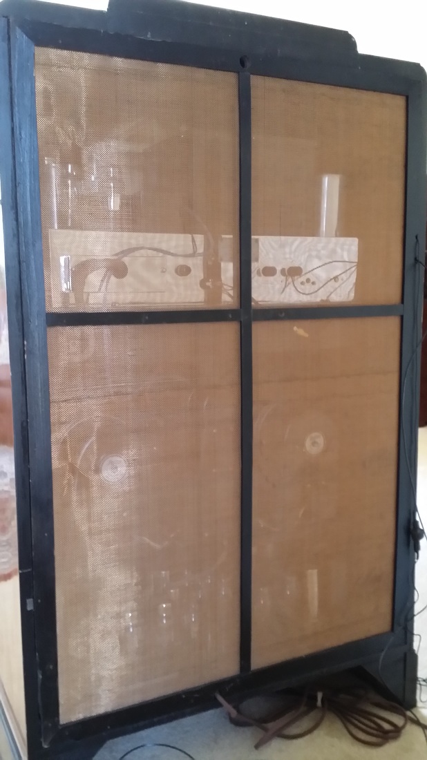
Here is the nice screened back that can't be in place if you want to access the radio/phono switch.
Somebody recommended bronze screen which looks nice and is tough but this back had regular window screen in it when it arrived. Well the bronze is going to look nice if the back has to be set aside anyway.
Somebody recommended bronze screen which looks nice and is tough but this back had regular window screen in it when it arrived. Well the bronze is going to look nice if the back has to be set aside anyway.
I installed a new long-wire antenna,
Video below, demonstrating:
First the Variable IF ( treble increase)
Second the tweeter on/off switch (upper left)
Third Shadow meter
Forth (click) Q AVC on
Fifth Tune off station (Q AVC turns on and mutes audio)
Bass is set at a relatively low level.
Sorry about the political programing- Talk Radio Host interviewing some Ding-a-Ling on the phone - not much else available - good thing for the Q AVC
Some observations about the Strat:
First, as I find things that could be better I have to keep in mind that this radio was designed in 1934. Compared to radios of the time it is clearly at the highest level for quality, performance, options and sound.
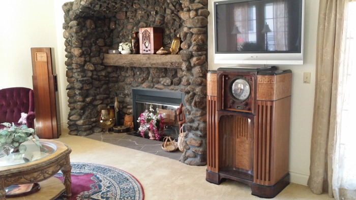
The cabinet is wonderful. It will be months before I can walk through the room without looking at it. It would have been better if they had built the top as a frame rather than letting the end grain of the structural wood exit the routed edge on the right and left resulting in small but unnecessary cracks in the lacquer.
Yes! Put a Radio/phono switch on the local distance switch - or somewhere accessible.
The power supplies are running at about 122V on the primary. It takes a LONG time before the transformers get noticeably warmer than room temperature.
It looks to me like they goofed up the measurements for the radio chassis height/ knob shaft exit points. Their rubber bumpers could have been really tall in the back, but in any case 2 or 3 shorter ones need to be in the front. With the thick bumpers available today, cut two down to 2/3 height with a knife. These will simply sit at the front of the chassis. Then, with the chassis bolts, tighten down the front bolts on the right and left until the shafts are exactly in the center of the holes.
I'll bet that a volume control with a switch rated for 360W was not available so the on/off switch is external and tripped by a lever attached to the volume shaft and secured by a grub screw. The spacing of the switch and the set point for the lever is critical. For one, if the set point is wrong the radio may turn on at a high volume, Secondly if the set point is wrong or the spacing is wrong (adjustable) you may find yourself pulling the radio chassis out just to turn off the radio. Don't ask me how I know this.
There is a lot of interplay between the volume and the bass level, it can be a two handed operation. The best fidelity seems to be in the upper 1/4 of the volume range. There is also less chance for hum/rumble at this setting. When playing a record or MP3 use less input raise the volume and bass level. There can also be a slight hum with the local distance switch set at distance however this setting would probably indicate a higher volume setting as well so it might not be noticed. There might also be some hum/rumble at very high bass settings. There is a lot of bass. It is probably never necessary to turn the bass control up this high.
I had not mentioned this elsewhere but it is necessary to know that there are two stages of RF amplification before the 6A7 Only one of them is used up to band 4. Nether RF amp is used on band 5.
The AVC circuit works very well.
Using a 47 behind the shadow meter is a little dim. A 44 will not help unless the series resistor is removed. Then it might get too hot.
The band/panel light bulbs run at line voltage. Wafer "A" switches line voltage!
The radio would benefit from a better antenna coil, maybe with separate secondarys for each band - yeah I know, it was designed in 1934. Edit: I see that they changed this configuration between the first and second production runs.
Centering the broadcast band between the high end trimmer and the low end padder is difficult.
No, I'm not going to restore another one.
2 Week update:
The quest for a GOOD 6A7 seems successful now. The original died slowly loosing the SW bands. The 2nd tube tested really good but was noisy and drifted. The third tube is good, so far. Realigned radio on living room floor. I can pull the radio chassis in less than 15 minutes now - probably not a valuable skill, but - - .
Statement above amended to: I probably won't restore another one - - for a while.
First, as I find things that could be better I have to keep in mind that this radio was designed in 1934. Compared to radios of the time it is clearly at the highest level for quality, performance, options and sound.
The cabinet is wonderful. It will be months before I can walk through the room without looking at it. It would have been better if they had built the top as a frame rather than letting the end grain of the structural wood exit the routed edge on the right and left resulting in small but unnecessary cracks in the lacquer.
Yes! Put a Radio/phono switch on the local distance switch - or somewhere accessible.
The power supplies are running at about 122V on the primary. It takes a LONG time before the transformers get noticeably warmer than room temperature.
It looks to me like they goofed up the measurements for the radio chassis height/ knob shaft exit points. Their rubber bumpers could have been really tall in the back, but in any case 2 or 3 shorter ones need to be in the front. With the thick bumpers available today, cut two down to 2/3 height with a knife. These will simply sit at the front of the chassis. Then, with the chassis bolts, tighten down the front bolts on the right and left until the shafts are exactly in the center of the holes.
I'll bet that a volume control with a switch rated for 360W was not available so the on/off switch is external and tripped by a lever attached to the volume shaft and secured by a grub screw. The spacing of the switch and the set point for the lever is critical. For one, if the set point is wrong the radio may turn on at a high volume, Secondly if the set point is wrong or the spacing is wrong (adjustable) you may find yourself pulling the radio chassis out just to turn off the radio. Don't ask me how I know this.
There is a lot of interplay between the volume and the bass level, it can be a two handed operation. The best fidelity seems to be in the upper 1/4 of the volume range. There is also less chance for hum/rumble at this setting. When playing a record or MP3 use less input raise the volume and bass level. There can also be a slight hum with the local distance switch set at distance however this setting would probably indicate a higher volume setting as well so it might not be noticed. There might also be some hum/rumble at very high bass settings. There is a lot of bass. It is probably never necessary to turn the bass control up this high.
I had not mentioned this elsewhere but it is necessary to know that there are two stages of RF amplification before the 6A7 Only one of them is used up to band 4. Nether RF amp is used on band 5.
The AVC circuit works very well.
Using a 47 behind the shadow meter is a little dim. A 44 will not help unless the series resistor is removed. Then it might get too hot.
The band/panel light bulbs run at line voltage. Wafer "A" switches line voltage!
The radio would benefit from a better antenna coil, maybe with separate secondarys for each band - yeah I know, it was designed in 1934. Edit: I see that they changed this configuration between the first and second production runs.
Centering the broadcast band between the high end trimmer and the low end padder is difficult.
No, I'm not going to restore another one.
2 Week update:
The quest for a GOOD 6A7 seems successful now. The original died slowly loosing the SW bands. The 2nd tube tested really good but was noisy and drifted. The third tube is good, so far. Realigned radio on living room floor. I can pull the radio chassis in less than 15 minutes now - probably not a valuable skill, but - - .
Statement above amended to: I probably won't restore another one - - for a while.

 RSS Feed