
Say it isn't so!
This is a follow-up to the chassis restorations presented below:
https://www.russoldradios.com/blog/back-on-the-farm-radio-again-zenith-5-f-134
https://www.russoldradios.com/blog/back-on-the-farm-radio-again-zenith-5-f-134
In that post we discussed differences in the 5516 chassis - and replated a couple of them.
Obviously, each cabinet is different and this chassis was placed into 6 different models. Production changes are expected and were not particular to Zenith. Philco was notorious for dozens of changes in some 1930's models as were many smaller manufactures.
What is unusual are the undocumented changes to this chassis in that the published schematic represents a version that had a significant flaw and most radios found do not comply.
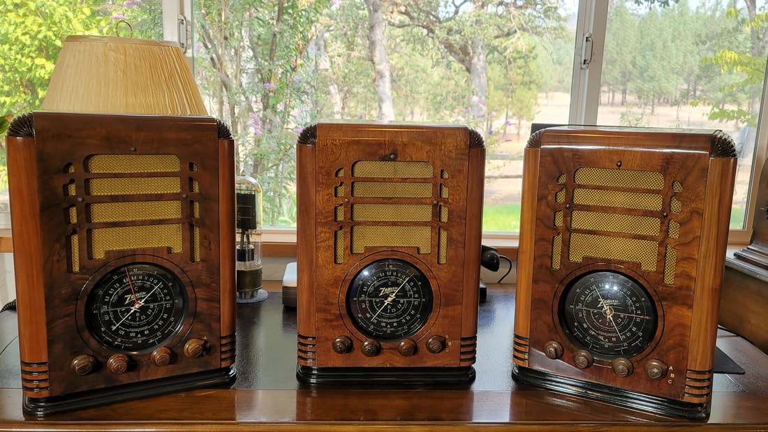
Pictured above is the 5-S-127 chassis that I replated and restored in the previously mentioned post. This layout is what is typically found.
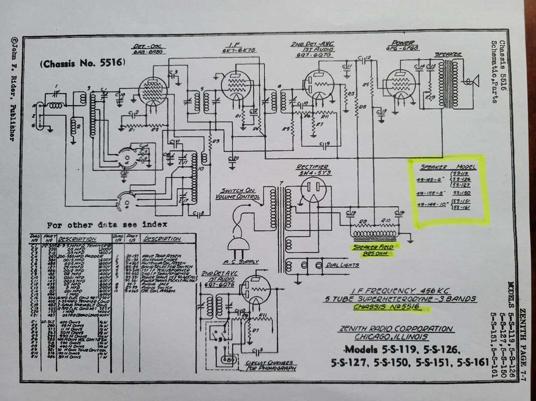
But , take a look at the schematic. Many restorers have come to this point and then spent days trying to figure out why their radio is significantly different. And it appears that the largest fraction of chassis produced DO NOT conform to this schematic or parts list, BUT their radio seems to work fine.
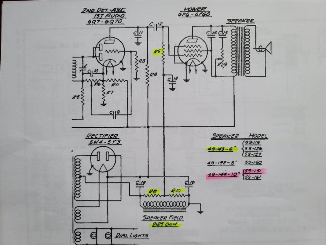
What is worse is that if you try to follow this schematic the result is a radio that works - poorly.
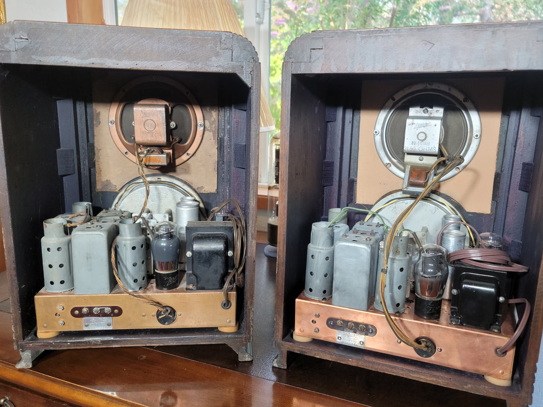
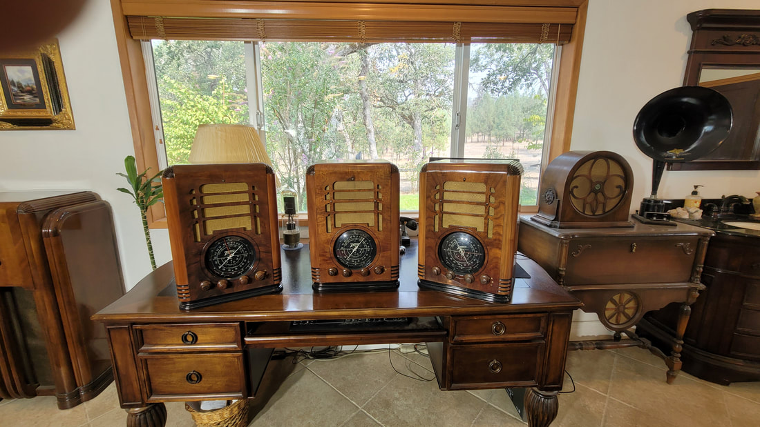
Most noticeable is the difference in the field coil impedance, most as-found with 1000 ohm field coils. In these radios the power transformer is significantly larger. In the second picture (from the top) you can see both the size difference in the PTs and different speakers.
The "spec" field coil is 2125 ohms (or 2150).
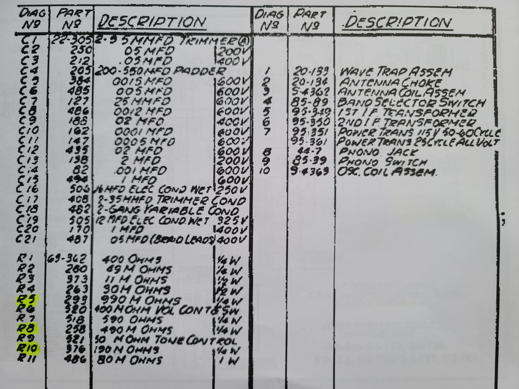
When you dig deeper a person finds that R5 and R10 are way off from spec - not that they drifted, it was built that way! R10 is most often 490k ohms rather than 990k ohms and R5 is 240k ohms rather than 190k ohms.
I have heard it said that these differences were to accommodate the different field coil values and that is probably true since you would need to change these parts to accommodate the larger field coil impedance.
Well, then why doesn't it work? Or, why does the radio with the 1k ohm F.C. work so well with the wrong resistor values?
I should note at this point that there are several other differences, like band switches that are different enough to require different knobs in order to point to "A", "B" and "C" and a lot of minor stuff.
Above, as found - as most are found not conforming to the parts list. This radio would have (does have) a speaker with 1K ohm F.C.
Above, conforms to the schematic, has a 2150 field coil and works poorly.
So what is the deal?
Most people speculate that parts availability explains the need to "redesign" the radio in mid production, but here is the problem:
A radio with the 2125K F.C. and the non-spec resistors (R10 240K, R5 490K) will have about 285V on the 6F6G plate and -37V bias on the grid. This is almost twice the allowable bias according to the RCA tube manual which shows -20V on the grid.
A radio with the 2125 F.C. and the resistors on the schematic (R10 190K, R5 990K) will have 167V on the 6F6G plate and -27V on pin 5, the grid. This is better but the audio is still limited and settings in the upper third of the vol. cont. range are distorted.
A radio with the 2125 F.C. and the resistors on the schematic (R10 190K, R5 990K) and the 1.5K ohm resistor placed in parallel with the F.C. will have 255V on the 6F6G plate, 265V on the screen and -21V on the Grid. The radio will work normally and the volume is good through the range.
A radio built with the " non-spec" resistors (R10 240K, R5 490k)) but with a 1000 ohm F.C. (49-165) will work just fine as-is..
Note that:
Higher line voltages today will also raise these voltages somewhat.
The speaker F.C., though in the return leg, was designed to avoid the typical candohm used to generate a negative bias voltage and provide some ripple filtering on the B+..
A resistor in parallel with the F.C. does not offer the same inductance so some hum might appear, though this was not the case on mine.
I checked both 5-S-119 and 5-S-126 radios on display in the museum and they were the 1000 ohm F.C. variety.
I checked as many radio pictures as I could find on-line and they were consistent though I don't know their history and a lot of pictured radios had owners/restorers that I referred to earlier (WTH is going on here???) so my first hand observations of original and mostly original radios is the basis of my conclusions. Input is invited.
B+ on the detector was also high. Spec. is 75V and it was as high as 150V in some configurations. B+ was high everywhere do to the decreased load presented by the 2125 ohm F.C.
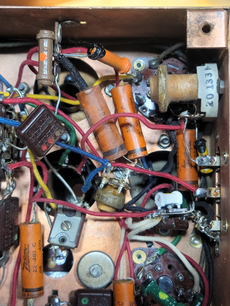
There would be better ways to "fix" this problem but most would result in several visible changes to the layout. What I chose to do was use the parts as speced in the schematic and add a 1.5k ohm 3W resistor in parallel to the 1K field coil. This increases the current draw on the B+ by 20ma and does not seem to cause a noticeable temperature rise in the stock (smaller) P.T.. I partially offset the total draw on the P.T. by using LED lamps for dial lights. (small light green WW resistor above)
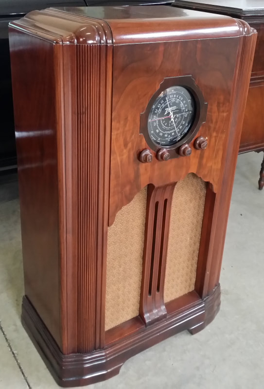
Above is my 5-S-151 console who's chassis is described by this schematic. It calls out another 2125 F.C. speaker, 49-144, a 10 inch model.
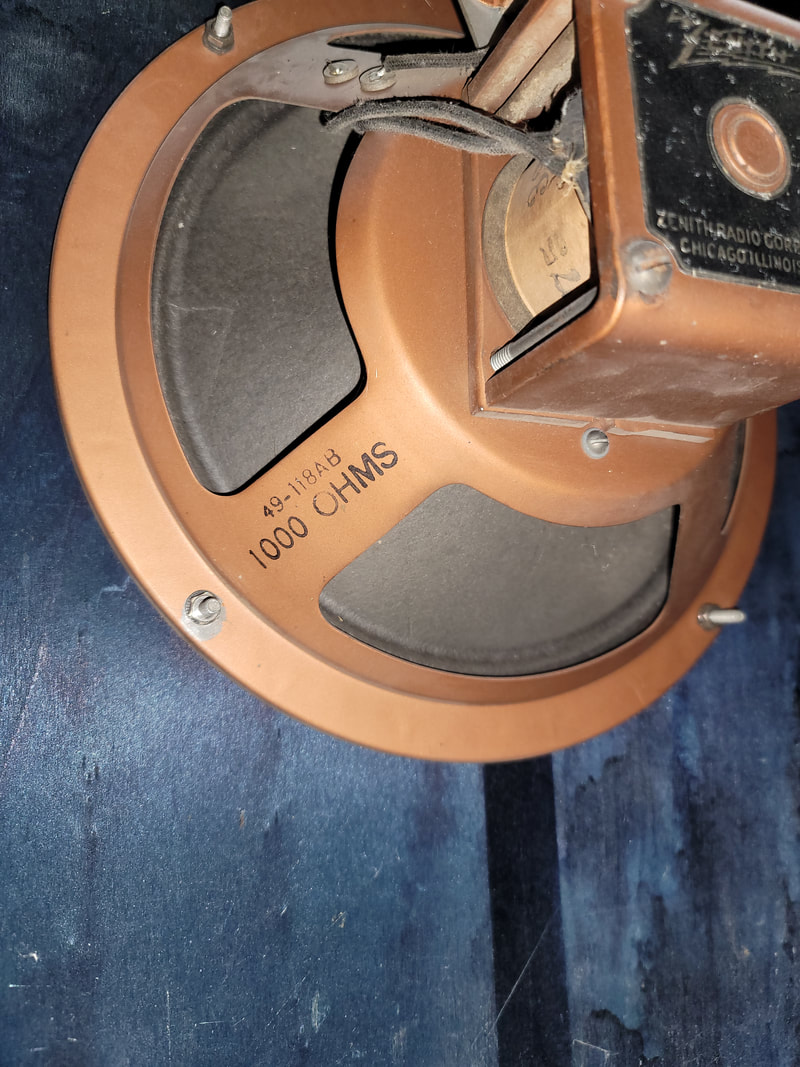
This is the speaker that is actually in the console - a 1000 ohm unit, (49-118AB). I have never seen a console with the 2125 ohm field coil speaker, (49-144). I do not know if they exist.
So what percentage of chassis/speaker combinations are compliant with the schematic - I do not know. At this time, I have the one pictured. From my files I found one that was sold about 10 years ago to a local fellow that used it at night to drown the high pitched whine caused by tinnitus. I don't recall much more about that unit though it was a "looker" (cabinets really do vary a lot). If he was to read this post, I would like to do a check-up on that radio too.
In conclusion, for what ever reason, Zenith built quite a few of these chassis/speaker combinations that worked poorly. The change was probably to correct this error. The power transformer change was probably called for by a slightly increased B+ load. The error is well documented. It would make sense that the error was in early production. In mine it appears on the plated chassis rather than the painted chassis though I am not certain if this is always true.
See also: https://www.antiqueradios.com/forums/viewtopic.php?f=1&t=401068
Has anyone ever seen a schematic with the proper parts?
Russ
P.S. I want to tell you about the lighter colored 5-S-127 cabinet with the replated chassis. I really like those veneer choices. So many of them are really dark.
And what is it with the 1937 Zenith band switch drawings - in particular the antenna switch section on the multiband radios? It seems to be in an impossible position. Those connections - the one connection alone - never occurs in any of the switched positions - maybe in radios with an X-band, but still that would have been specified. Best I can tell it was drawn with the contact rotating from the wrong direction BUT this is not the only contact on the wafer, those are correct.
AND have you checked a 6A8 on your Hickok tester lately. I found the settings on my roll chart ARE WRONG, particularly for the bias which is 30-something on the chart but only 11 on the trusted Consolidated Test Data For Hickok Model 533A-600A-605A Tube Testers. No wonder I've seen so many sales of "low testing" tubes.
I am still looking for 5516 chassis to further study (any variety) and complete projects. I also need period correct Zenith tubes. Thanks to all who have helped.
But Wait! There's More
Here are some more changes that apply to the later, large transformer/1000 ohm field coil units.
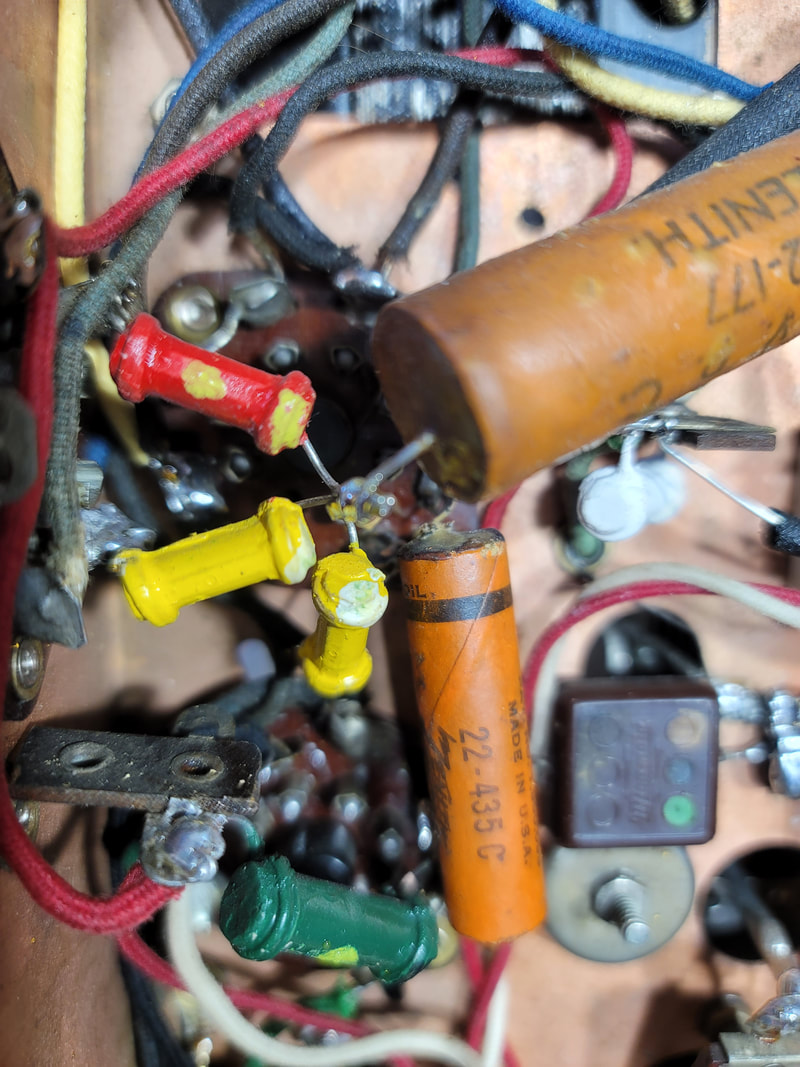
Above
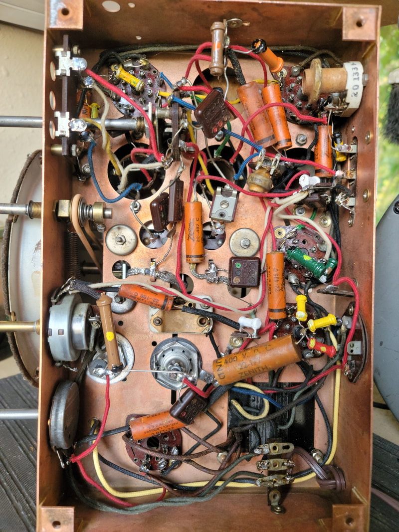
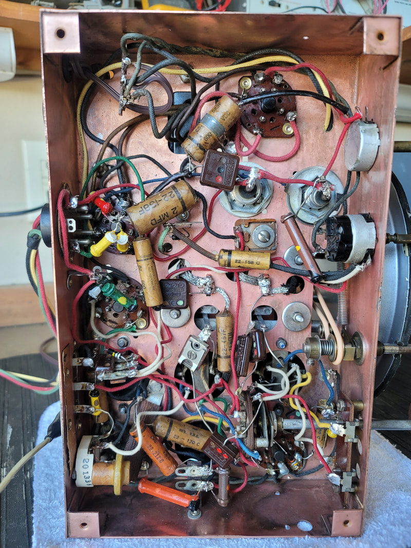
This chassis has a shield, wrapped in a fiber insulator, that extends over the 6K7G IF tube's base.
This chassis has a shield, wrapped in a fiber insulator, that extends over the 6K7G IF tube's base.
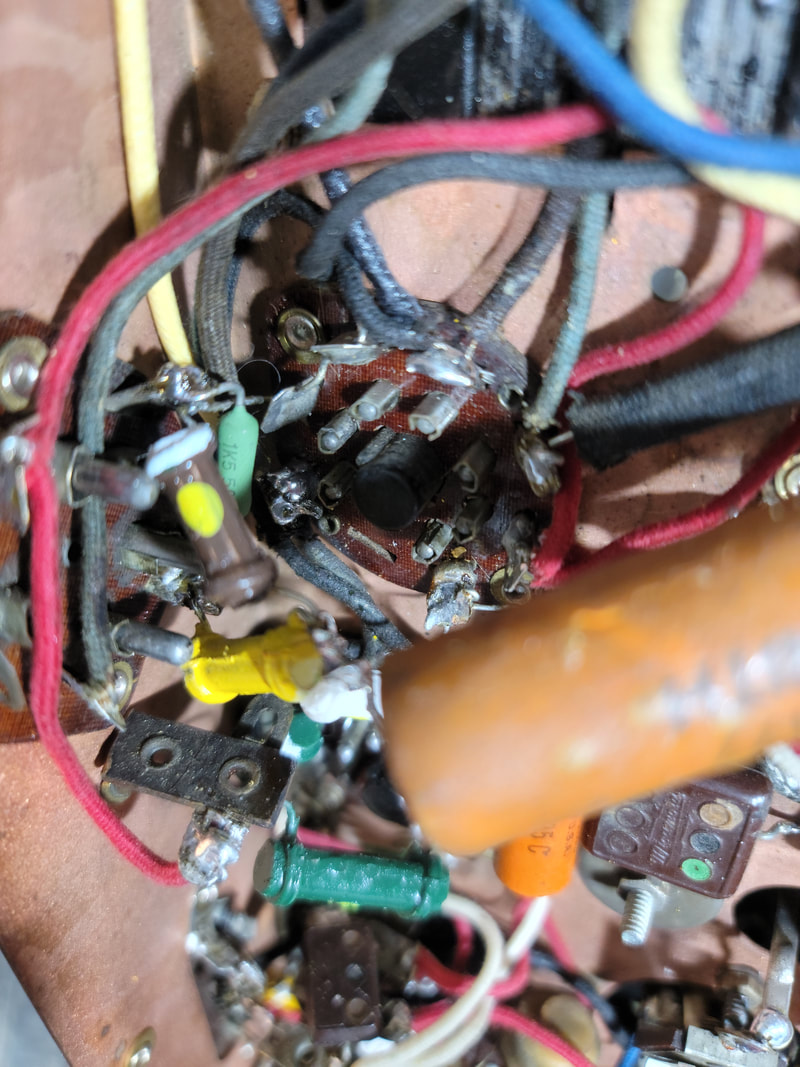
Above
Here is a close up of the shield.
Also note the bottom of the antenna coil (upper right under the trimmer cap). There is no external "Antenna Choke" part number 2 on the schematic. It is incorporated into the antenna coil and as a result the antenna coil has an extra ground contact which is missing from the unit pictured below.
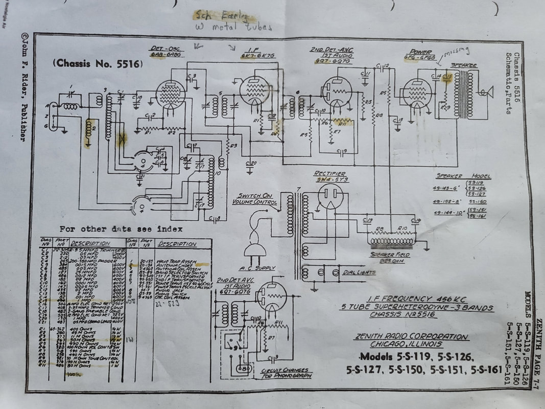
The schematic above highlights some additional parts changes besides the "antenna choke" #2.
C 15 .1 MFD 22-294 might be .05 MFD part # 22-523
R4 30000 ohms at 1/2 W might be 1W
R11 80000 ohms at 1W might be 100000 ohms
C 15 .1 MFD 22-294 might be .05 MFD part # 22-523
R4 30000 ohms at 1/2 W might be 1W
R11 80000 ohms at 1W might be 100000 ohms
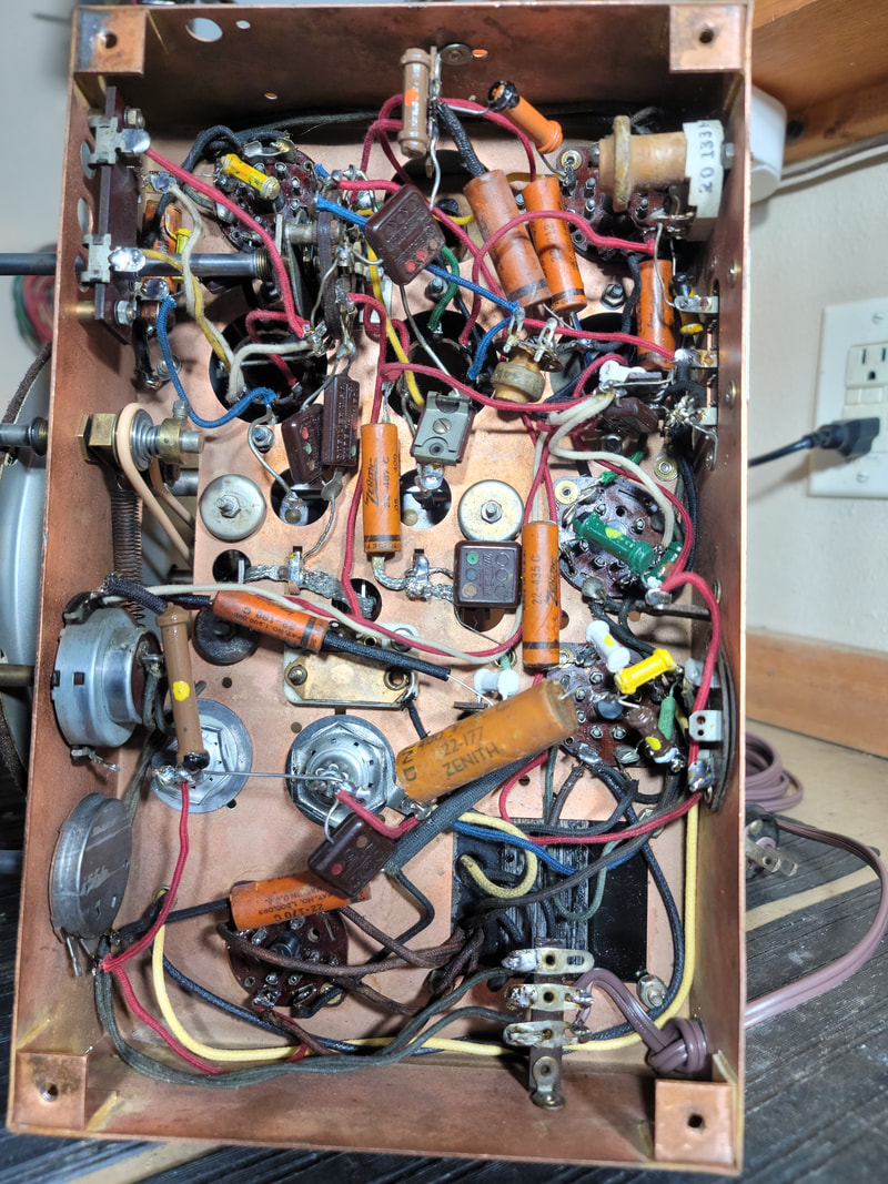
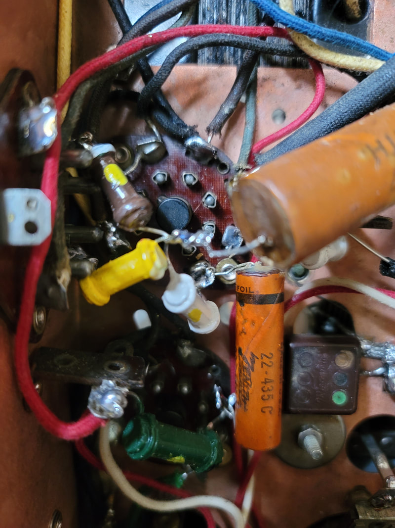
Above
Chassis W/O shield and with external "Antenna Choke" external to the Antenna Coil.
Chassis W/O shield and with external "Antenna Choke" external to the Antenna Coil.
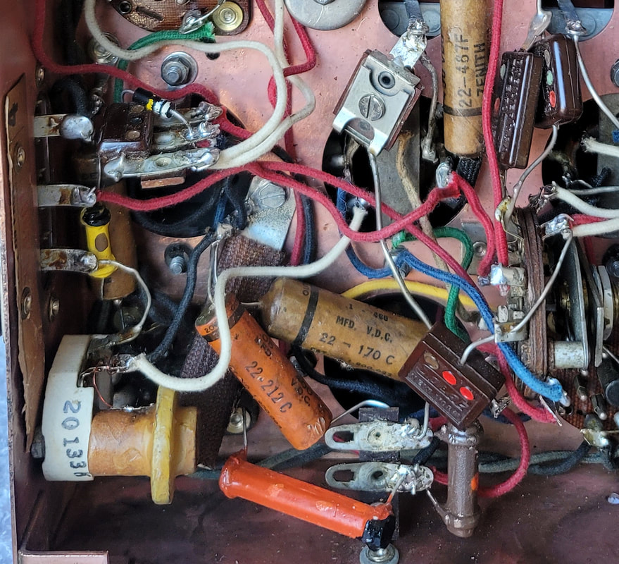
Close up of External "Antenna Choke" part # 2.
This part is wired as drawn on the schematic, just external to the antenna coil can.
This part is wired as drawn on the schematic, just external to the antenna coil can.

 RSS Feed