
The scene from our back-40 yesterday as the Worthington Fire grew quickly to over 500 acres. It is not yet fully contained today. Temps over 100 deg. F., humidity in the single digits, wind gusts ~15 mph.
|
This post is a continuation of the "Farm Radio" post below. When I purchased this radio off of P-Bay things were Covid-slow. So I decided to do a more in depth restoration of the chassis. Little did I know that Bill Reid was going to donate the rest of his collection - about 3 truck loads, but, more on that later. 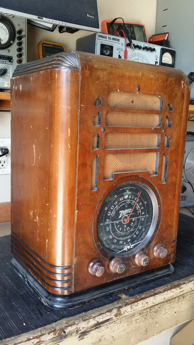 You usually see this cabinet with chassis #5516 which would make it a model 5-S-127, one of my favorite radios. Those are not uncommon. I think that the radio was as popular at the time of manufacture as it is now. There seem to be quite a few around, but popularity has driven up the prices above comparable radios by other large manufactures. 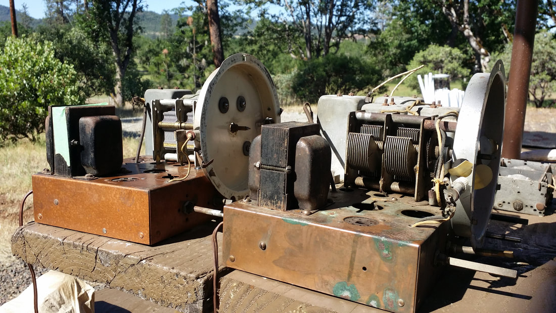 Above are a pair of 5-tube AC powered chassis. There was a lot of variation in this chassis construction. Even for the 60hz models, there were at least 2 transformers, at least 2 different speakers with different field coils which also created some circuit differences. So if you work on one of these be sure that you have the appropriate schematic. Other than the components, there was also a painted and a plated chassis that often has green, rusty patches like the one above. 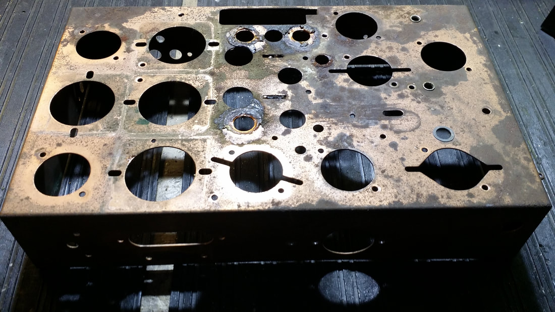 The battery powered chassis has a different layout than the AC versions. Somehow I failed to take a proper "before" picture prior to the removal of all of the rusty/corroded components. With everything removed it is easier to see the extent of the rust above. Note that there is no cutout for a power transformer. I don't like to paint chassis that were originally plated. Besides the issues with ground points being corroded and subsequently , painted, I just don't want a radio that has been altered in that way. SO it was time for MORE FUN WITH CHEMICALS AND ELECTRICITY! 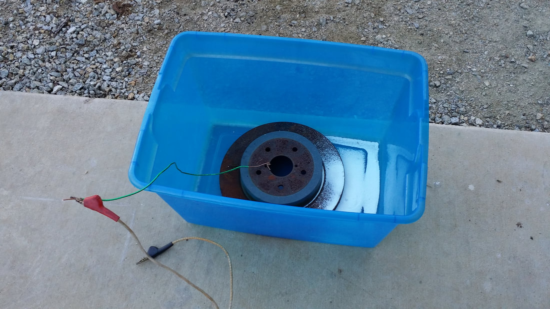 I had a disk brake hub that was keeping a tarp from blowing away. If you are going to de-rust steel a steel anode is necessary. NEVER use stainless steel. The white powder is washing soda, easily found at WM.  Just add water, hook your chassis to the NEGATIVE lead and suspend it in the solution, not allowing contact with the steel plate. I am avoiding using the term "Anode" here since it can be confusing, ESPECIALLY for a person that is accustomed to working with vacuum tubes. If you want to get it straight in your head, you will have to do some reading and I did not want to bore you here. The result will be a stream of bubbles coming off of the rusty chassis and a nasty looking film of orange gunk will float to the surface eventually sinking to the bottom. THE GASSES EMITTED IN THIS PROCESS ARE COMBUSTIBLE and that is why THIS SHOULD ALWAYS BE DONE OUTSIDE. And, if you are not absolutely sure about the technique DON'T DO IT AT ALL.  Remember when Circuit City went out of business? I went to the liquidation sale, late in the day. There I found the power supply that had been used for the car radio display and managed to acquire it for $25. I was not sure what I would use it for at the time - but now I do. You need a LARGE DC supply for rust removal. It does not need to be well regulated - or regulated at all, but you will need a few amps and 12V is a good voltage. You can use a car battery if you missed the Circuit City sale.  Then all you have to do is replate the chassis - NO, not with copper, with nickel, then with copper. Acid copper (bright copper) plating solution is too acidic to plate steel. Instead it will just turn black/nasty and corrode some more. You might want to fill some of the pitted places with solder - easier said than done. Solder works best on the nickel plate rather than the bare steel. Use an iron - NOT a torch. I really don't do this all that much (and for that reason, take my advice with a grain of salt - like you usually do). I was happy with the results. Kinda' PINK, but it will be the color of an old penny after a while.  Did I mention having to remove EVERYTHING from the chassis including all of the riveted components? Well, now you have to put it all back! Some people use bolts or screws. I use rivets like the originals, besides, isn't hitting a chassis with a hammer something you have often wanted to do? BUT WAIT - THERE'S MORE! Almost every metal component on these chassis are plated with something. The tuning cap is plated with nickel (not the aluminum plates) and the IF transformer cans are plated with zinc. Talk about dissimilar metals! I think that the cans needed to be plated to avoid corrosion of the base metal which seems to be aluminum. After dealing with the nickel plated components I moved on to a new challenge - zinc plating - which is supposed to be easy(er). 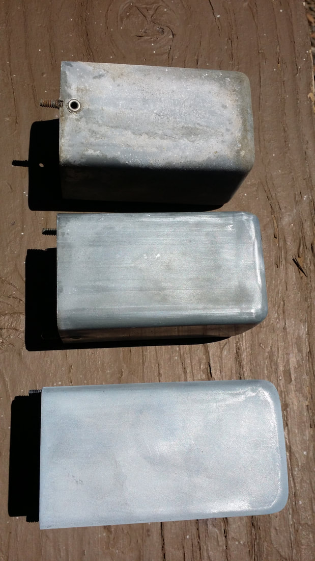 Above: IF and RF coil covers. As found Sanded/cleaned up Replated Keep in mind that I am showing you what I did, not telling you to do it. Below is the configuration I used for plating zinc. The zinc foil, which is very soft/bendable, was purchased for very few $ off of Amazon. The plastic bowl I borrowed from Sue. I don't think that she will miss it - - or want it back. You must use a variable voltage power supply. So the big sucker pictured above will not do. 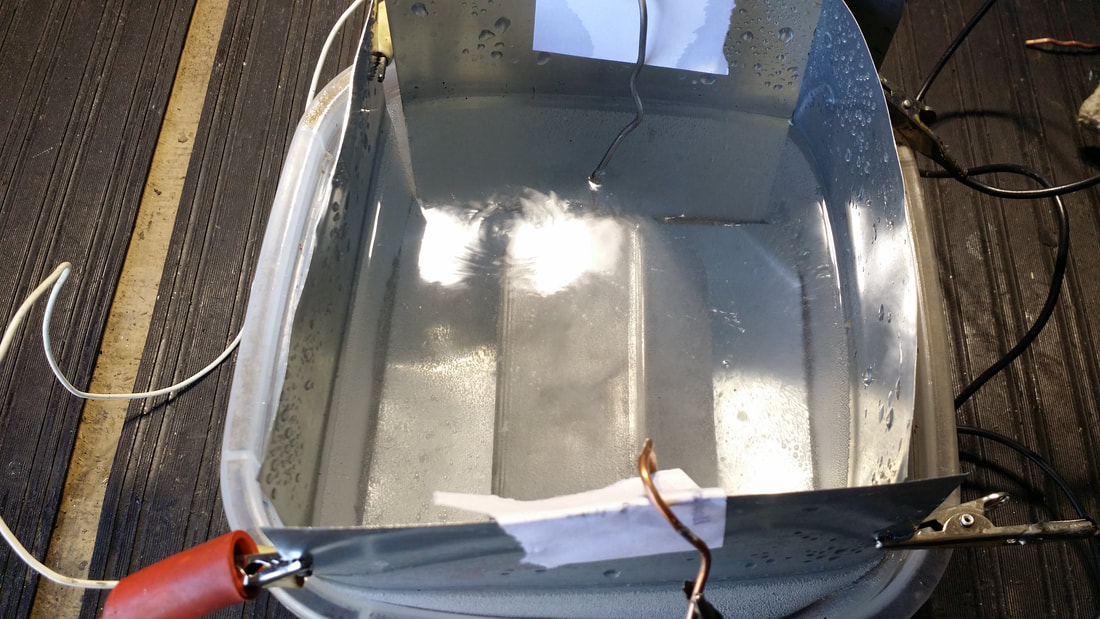 I easily formed the foil to the shape of the bowl insuring electrical contact for my + connection. The part was hung off of 14 ga. copper wires and the little pieces of paper insulated against shorts and subsequent explosions. (see gasses are explosive above) 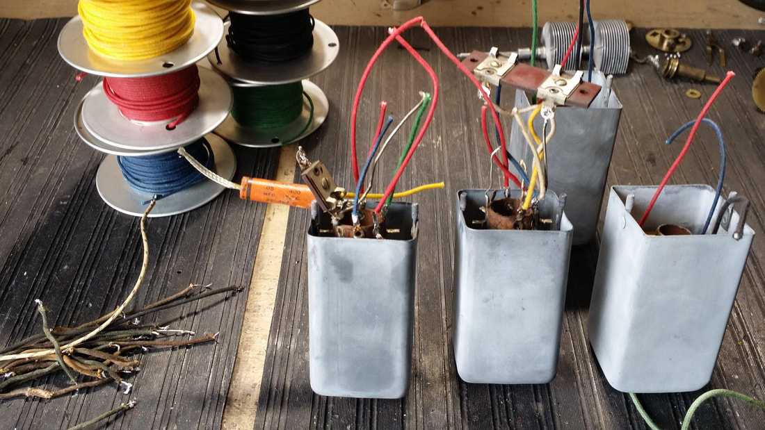 At this point I should mention that I performed this process on the 5516 (AC) chassis, pictured at the top of the post, as well as well as the battery powered chassis that was going back into the cabinet. I have found that once a process is started it is easier to continue rather than restarting (and relearning) it later. So the pictures of re-plated items are a composite of both chassis. The IF/RF transformer cans came out a dull grey, just like I expected them to be. During the plating I noticed that the zinc could appear more like a galvanized finish if I deposited less zinc on the base metal. This included the wavy lines and markings typical of a galvanized surface. So if you like that, stop sooner. Some more notes: I needed a dielectric to transport zinc ions and water alone will not do - maybe salty water, but I did not try that. I saw somewhere on the internet (source of all wisdom) that a person could use the washing soda used in stripping the steel to make a solution. I tried this. One way to see if your setup is working is to monitor the amperage on your power supply and watch for the small bubbles. There were bubbles - and bubbles - and nothing else. So I decided to ditch the washing soda water for clean in which I deposited about 2 tablespoons (use plastic spoon) of battery acid (sulfuric acid) - - do I really need to tell you not to do this? Anyway, now there was some action. At first I needed to set my supply at about 15 volts . BUT, by the time I finished 4 of the cans I had dropped the plating voltage to about 1.5V. (that is one and a half volts) I suspect that the process formed zinc sulfate in the dielectric which encouraged the transfer of zinc to the plated surface. Had I maintained the 15 volt initial setting, I would have destroyed the can and the foils and - you know - sparks, fire, explosion. So if a person was to try this - and I know that you won't - careful monitoring is absolutely necessary. Zinc sulfate is a component of fertilizer, but I would not pour this stuff on the flowers. I dispose of chemicals responsibly. 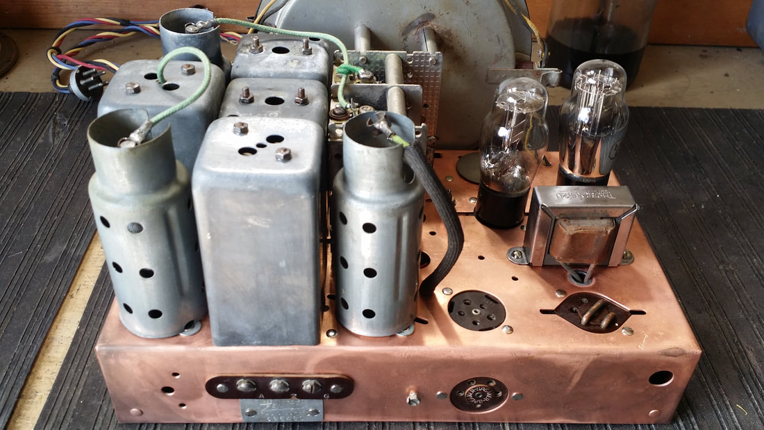 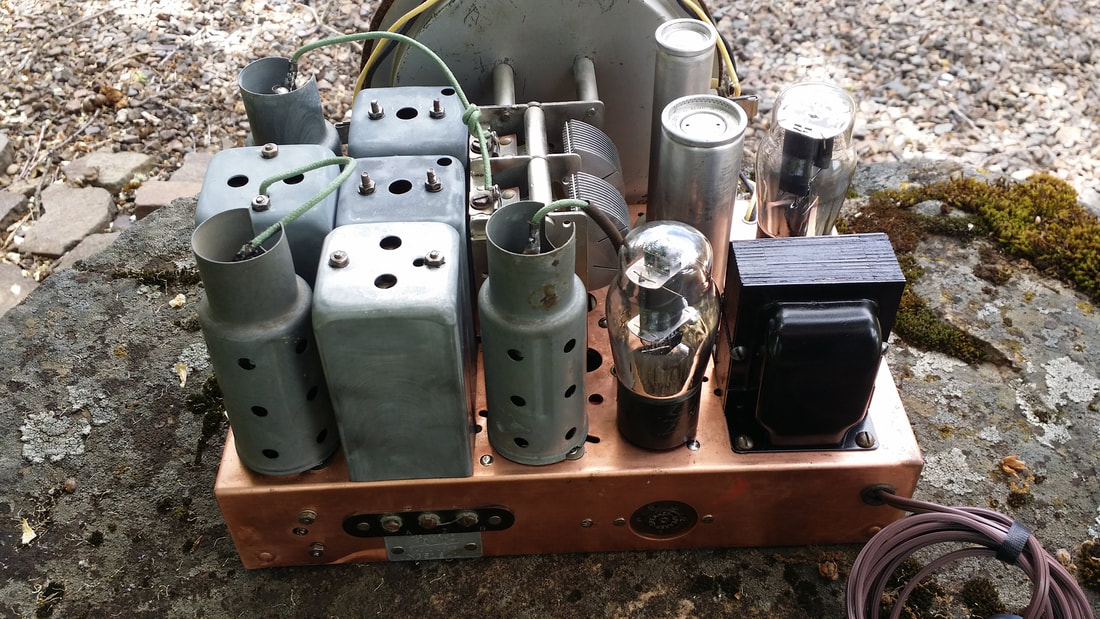 Both chassis above. I could have plated the tube shields s well but they were not in bad shape. This is a good comparison of the DC and AC powered chassis. 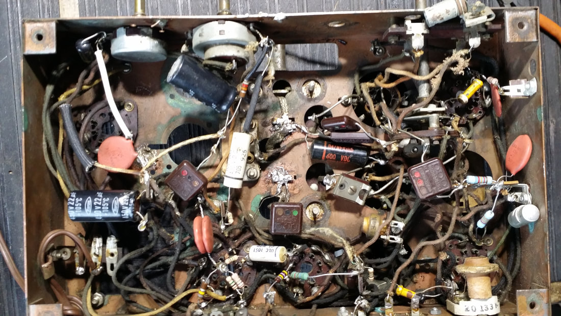 Above and below are the before and after pics for the AC chassis 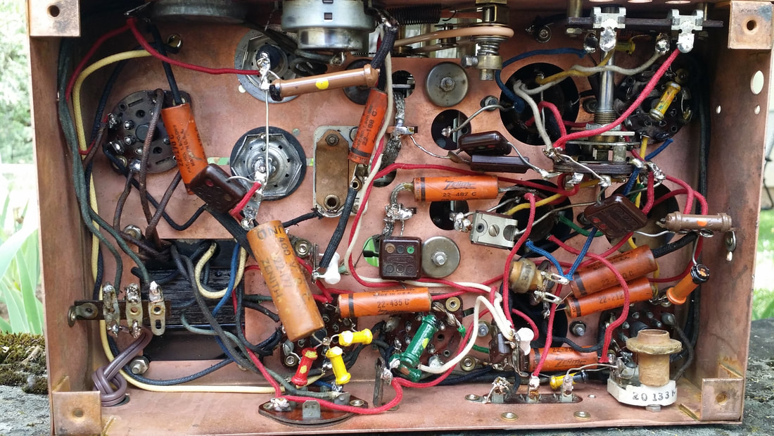 It should be noted that it is difficult to "throw" the plating into the corners of the chassis. And that I stock the original Zenith caps for those chassis that have lost them. 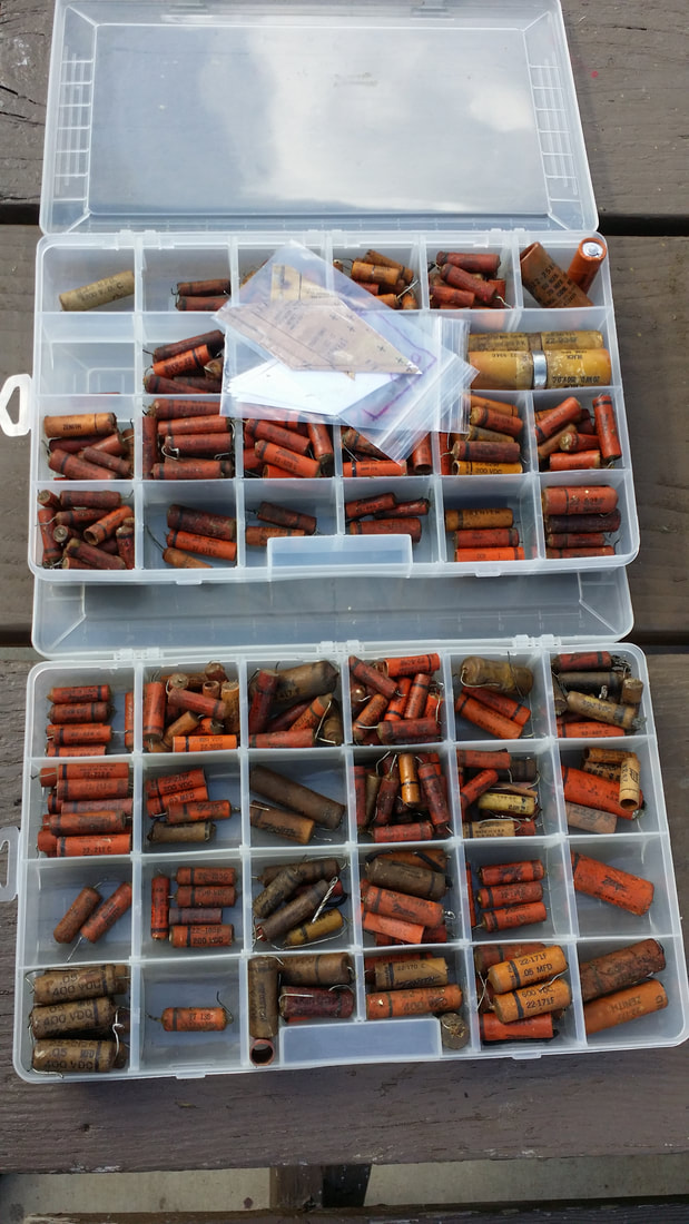 Thanks to Harry L. for a lot of those old caps. 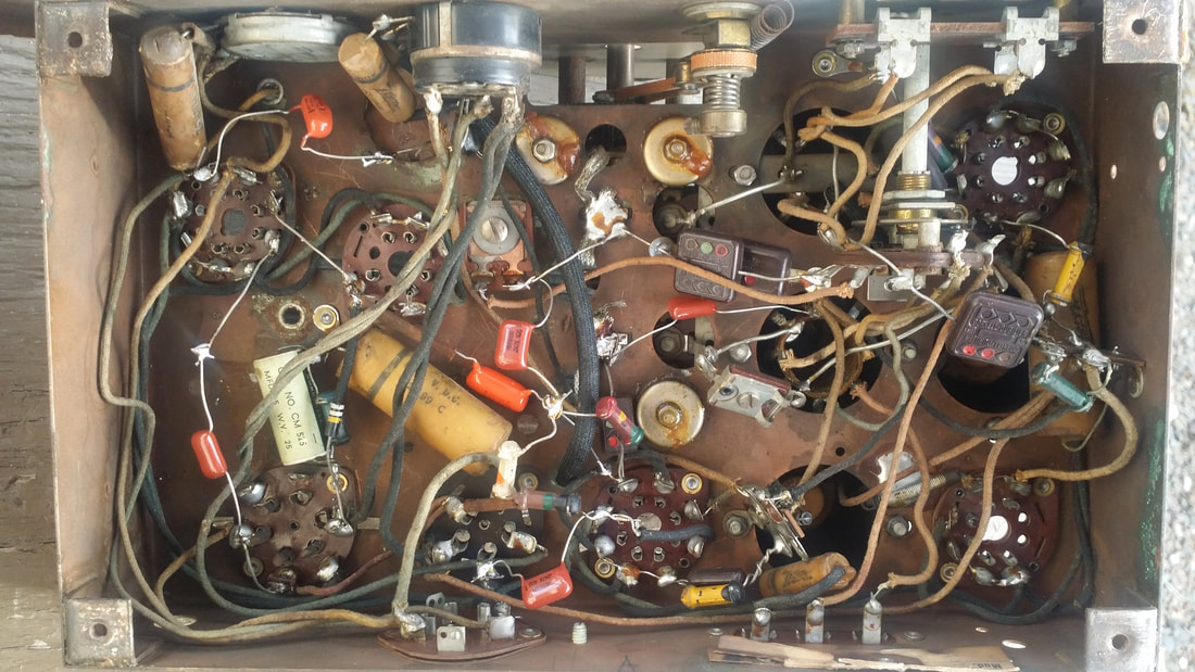 Above and below are the before and after pictures of the DC powered chassis 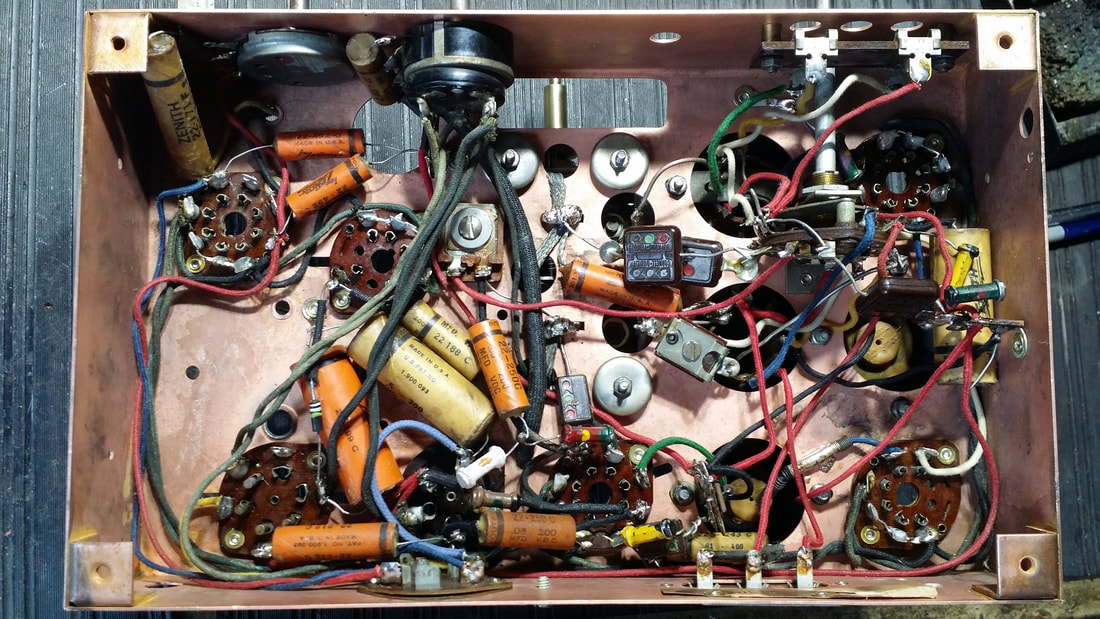 Now, back to specific differences between the AC and DC powered radios. 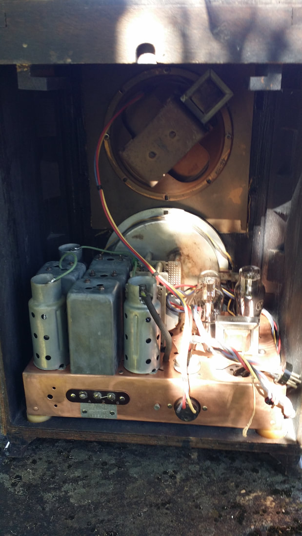 The cabinet used for the 5-F-134 is different than the one used with the AC chassis. Note the 2 wooden brackets near the top of the cabinet. These are used to slide in a vibrator power supply which would have used a 6V battery as a power source. The brackets, along with some other modifications, make the battery radio cabinet heavier than the AC chassis cabinet. I had always thought that a radio with the brackets and without the vibrator supply was simply missing that supply. But, no, there is another configuration for storage batteries, a setup that would be familiar to users of mid 1920s battery radios. 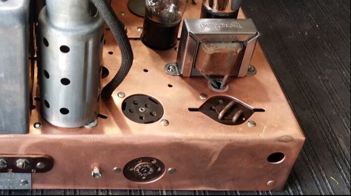 On this DC powered chassis there are 2 plugs on the top surface. One is to plug in the vibrator supply (right) and one is for the dry-cell batteries (left). On a radio optioned for dry-cells there are 2 heavy jumpers installed in the vibrator supply plug - see above. In this configuration a cable was provided to plug into a dry-cell assembly, A, B and C cells. So, on this chassis, the A supply was 2 volts and 2 volt tubes are used. The radio works well with about 140V on the B supply. A C- supply could limit current consumption of the final audio output tube. So it is perfectly normal to have a radio that does not use the top mounted vibrator supply. 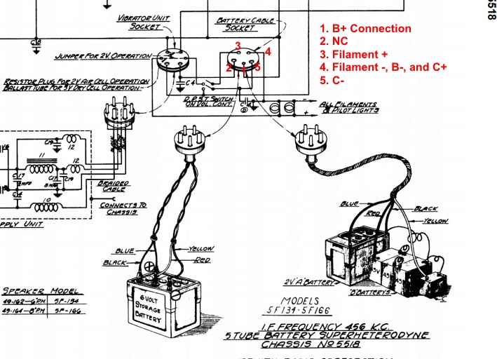 Image borrowed from the Antique Radio Forums site. The original image is from Riders (less the red text) 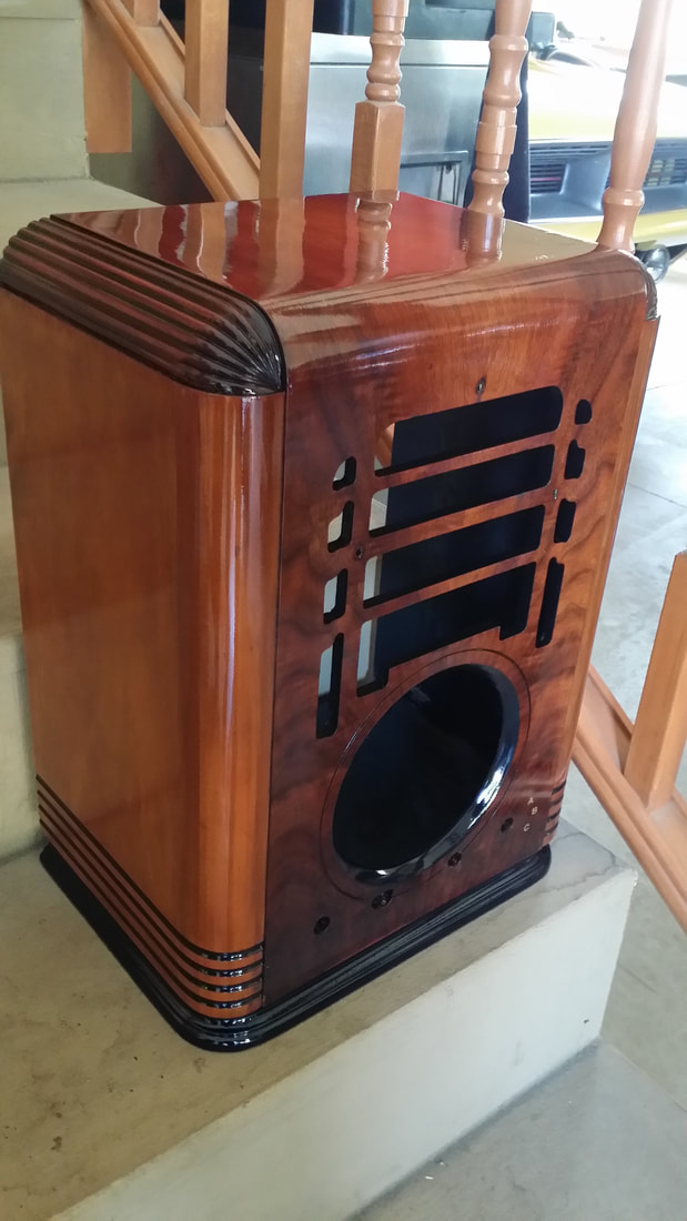 Of course, while I was having all this fun the lacquer was drying. 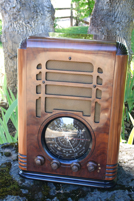 It looks even better in person. 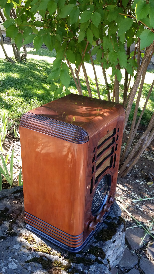 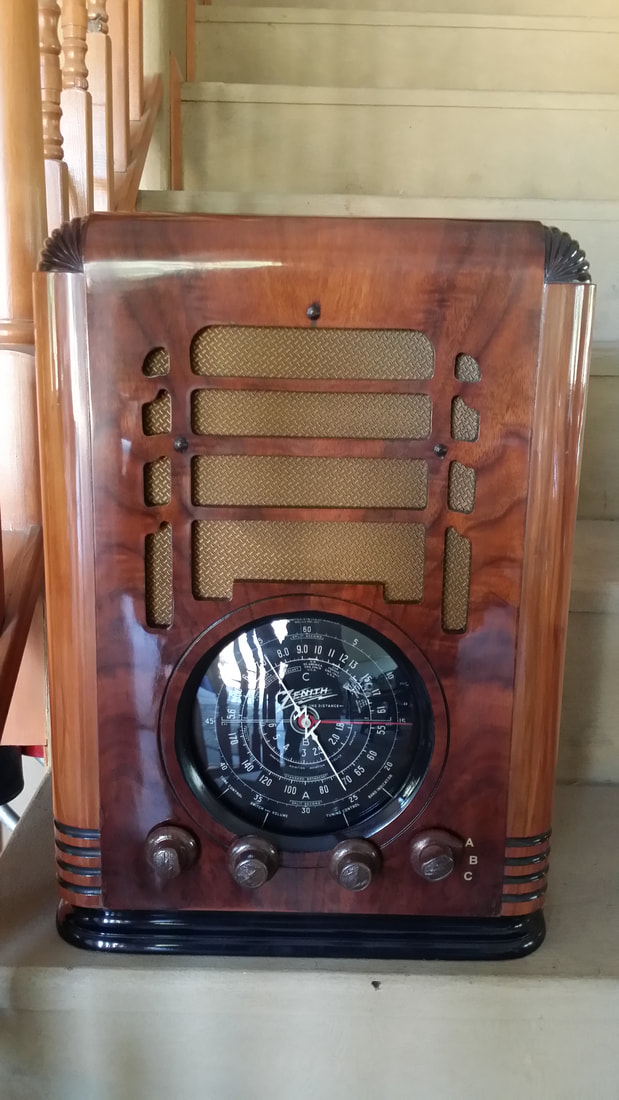 I have already started on some of the radios donated by Bill and some of those will be up next. Along with the old radios is some tube-type audio equipment, which I find interesting and useful. Though I have restored a lot of tube-audio gear, I have not posted much about them. Maybe we'll get into that next time. Russ - -and thanks Bill for filling up my shop ;-) Bill Hennessey has compiled a spreadsheet on the differences between the early model AC chassis and the later one: In the interest of working out the differences between Chassis 5516 Var. A and Var. B (the original subject of this post) I have created a Google spreadsheet with the stated values for the two known Schematics involved. I've also put in place the values as recorded by bastardbus for the Chassis 5516 Var. B. There are three tabs in the spreadsheet. One tab for the 5-S-127 Chassis 5516 Var. A (Rider 7-7 Schematic), the second tab for 5-S-127 Chassis 5516 Var. B (no known schematic, values from bastardbus), and the third tab for the 5-A-127 Chassis 5517A (Rider 10-15 Schematic). Those values listed in Chassis 5516 Var. B and 5517A that substantially differ from Chassis 5516 Var. A are in Red. https://docs.google.com/spreadsheets/d/1U_oBMYzxQR48MkZR6t7u7yo2bScMciomPMwI2XKKk8E/edit?usp=sharing I offer this in the hope it may help us to more easily track these capacitor and resistor values and provide some additional guidance to those hoping to restore their Chassis 5517 Var. B sets. Let me know if there are any additional values or data that should be considered for inclusion here. Right now, I've set this Google spreadsheet to allow comments, feel free to add comments on values that you have found in your own sets. Thanks! _________________ Michael Hennessey mbhdesign |
AuthorRuss Webb 
Russ Webb & Fuzzy
Best Buddy, Radio fixer Categories
All
Archives
December 2023
|
 RSS Feed