
This is the last of the radios given to me by Jerry: See posts below.
In 1928 Sparton (Sparks Withington) was still at odds with RCA over radio pattents. Without rehashing information that can be found elsewhere: http://spartonequasonne.webs.com/models.htm
I will give you some breif highlights of this Equasonne version.
First, I consider it a true Equasonne and by that I mean that it does not incorporate the RF stage added to later units - which really was an attempt to improve on the shortcommings of the Equasonne design and really was consideration for the possible infringement of the TRF design that Sparks was trying to skirt. And it also lacked the first AF stage that was added to some models, like my 930 (mentioned on the web page above). This modification basicly added a 484 or 485 triode to boost input to the audio final(s).
On this note it is important to consider the tubes that were used in these radios. Again, trying to dodge RCAs pattents, Sparks used their own tubes which were really only slightly different than RCA's with the significant difference being filament voltages.
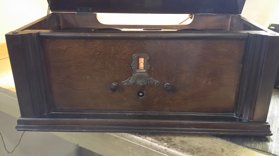
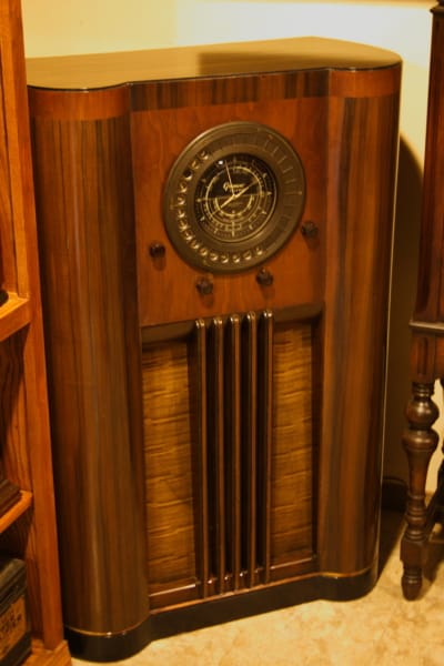
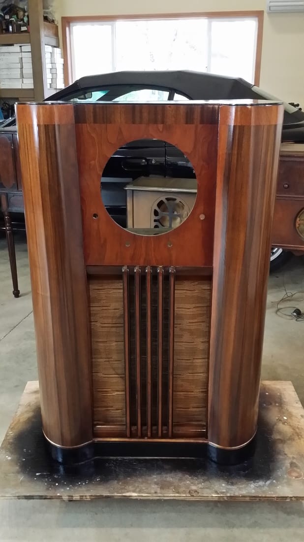
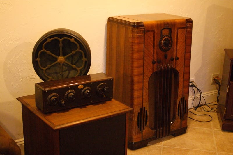
So the 69 is an AC powered table-top radio, very similar or exactly like the chassis used in consoles. This makes the chassis a tight fit. Especially when you consider how the modules are connected.
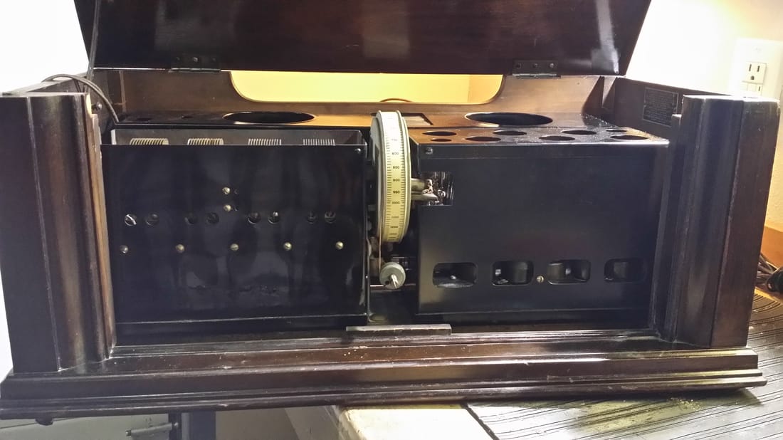
There are 3 basic modules in all Equasonnes with the rare addition of the audio stage mentioned above. In the back is the power supply/audio amp, front left, the passive tuner (no RF amplification) and then, on the front right, the RF/detector module.
As mentioned, and a serious consideration prior to undertaking any sparton Equasonne restoration is the fact that the cost of the radio is little compaired to the cost of the stock, Sparton/Cordon tubes. This version uses a Sparton 585 as the only audio stage following the detector. Now, for all practical pourposes a 585 is the same as a 250 which only slightly improves on the chances/cost of finding one if yours is missing. The other triodes are 485 (or 484s) which were easy to find and cheap but that is changing too. For practical pourposes a 56 can be used, NOT a 27, though this can affect the tuning of the already finicky RF stage. Read more on the site above on Sparton's suggestion for strong or weak tube placement.
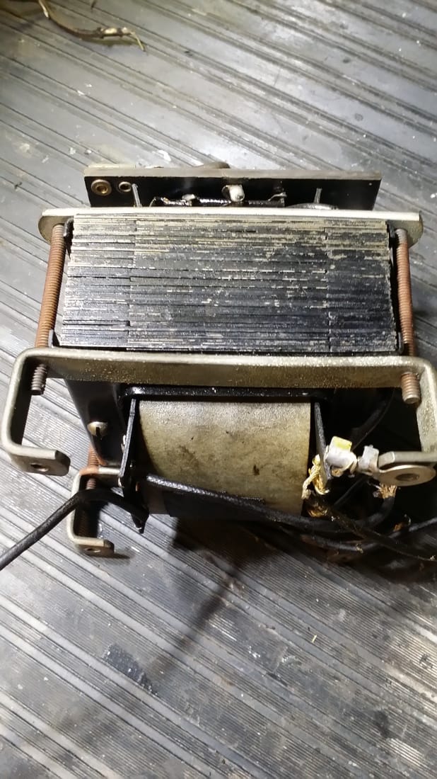
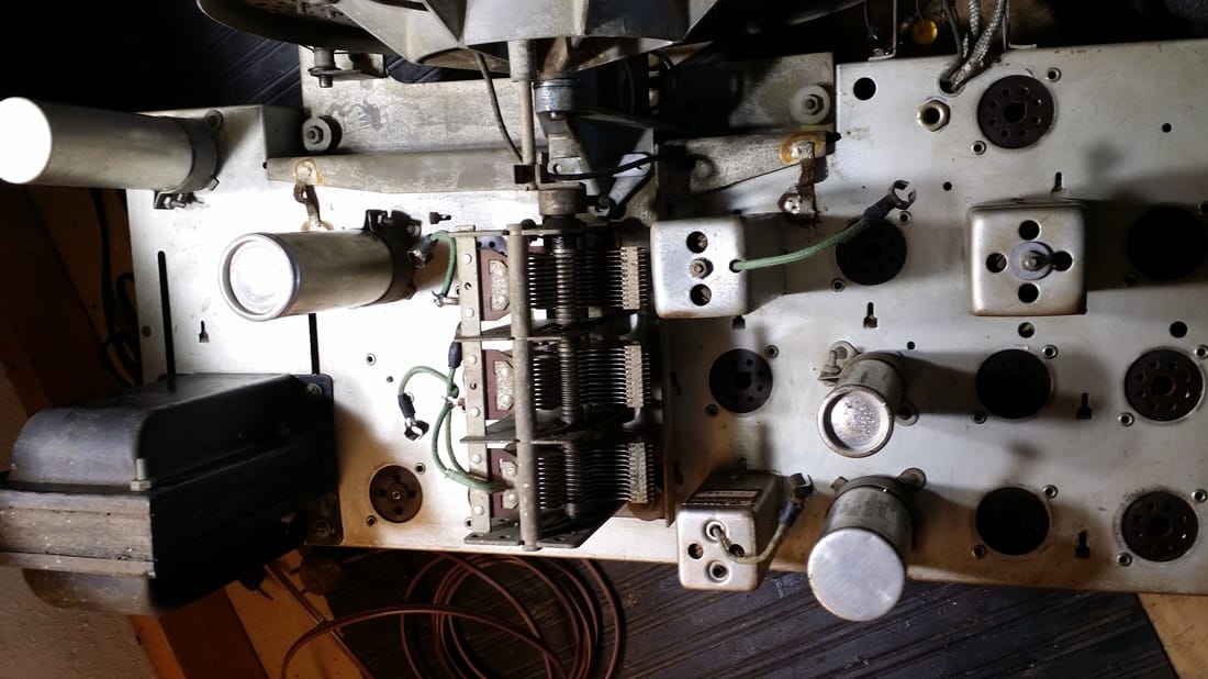
The most significant issure with this radio, other than the fact that all of the tubes were missing or wrong (27s), was the failure of the power transformer. At some time three of the 484s were replaced with 27s. This could have lead to, or at least contributed to the failure. Anyway one half of the HV winding was shorted.
I found a replacement on E-Blah. It had the same problem. The nice fellow refunded it;s cost. Having two inspired me to attempt a rewind. Replacements are few since the wierd filament voltages, 5, 7.5 and 3 are not standard on any other manufacture's radios.
The transformer I got off of the auction site had been heated so much that the windings has seperated since the tar and bee's wax had all melted out. It was easy to remove the HV from the center of the stack, inspect the primary and filament windings and then replace the HV with one I made. Well I measured the wire size and ohmed out the good side of the center tapped HV winding and got 324 ohms. A little consultation of the magnet wire chart got me going on a new one. This worked BUT I must have misjudged the wire size by one gague and ended up with a 450-0-450 volt B+ winding.
It would have worked. It needed about a 16k resistor but at about 50W - really big! So I moved on to the original transformer, knowing now what I did wrong. To make it a short story, I was sucessfull, though this one required some time in the oven to take apart. It was now at 325-0-325 volts for the HV prior to loading.
I could now move on to recaping the unit.
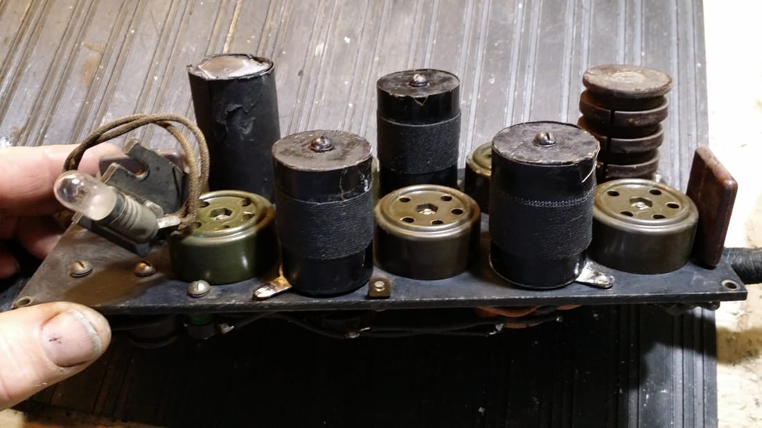
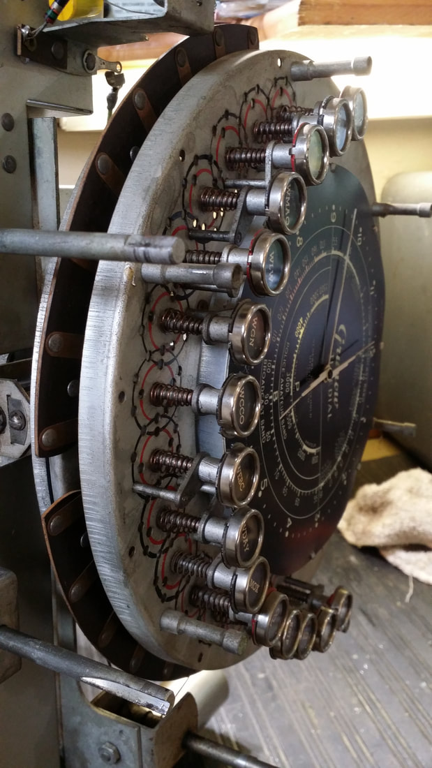
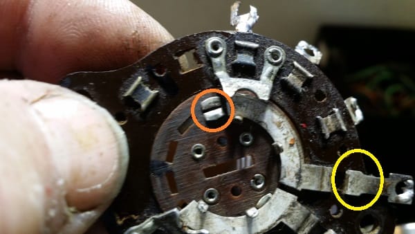
The biggest challenge in recaping the RF section is the odd construction of the original capicators and as usual, I wanted to keep the factory look. In the photo - 2 above - you see the tubular like things on the RF board. All but one of them is a 1uf cap. On the Equasonne page listed above he has a process that can be used. It was adapted for restuffing because a single replacement cap would not fit inside of the original.
I found that it was much easier to use two .47uf caps allowing me to leave the support rod intact. This also made the part much sturdier.

Fortunatly all of the other "iron" was still good.
There is one other thing I should mention for all Equasonnes, especially this model. That is the grounding of the modules which most might assume is accomplished by the multiconductor cable - but no!
There is one other thing I should mention for all Equasonnes, especially this model. That is the grounding of the modules which most might assume is accomplished by the multiconductor cable - but no!
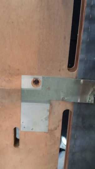
Above is sparton's ground system for later Equasonne models which was not used on the 69.
On this radio the most convenient way to ground all three modules togeather (required) is to strap them togeather at the mounting bolts.
On this radio the most convenient way to ground all three modules togeather (required) is to strap them togeather at the mounting bolts.
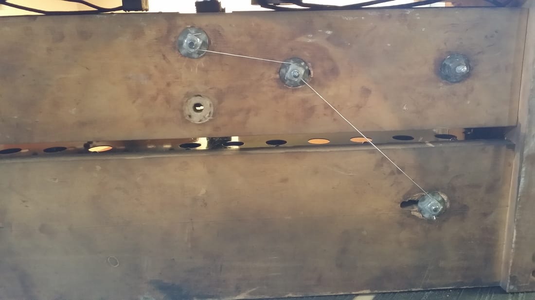
Though there were reminents of this type of connection prior to disassembly, I can't be sure that this is what the factory did - but I think that it is correct.
The design of the cabinet keeps these bolts and wire off of the table top. So unless something is dragged across the bottom the ground is rather safe. Opperation of the unit whithout this ground results in motorboating and other undesireable noises.
In conclusion, I find this radio to be an average/acceptable performer. Considering the design it is acctually superior to what you might expect and better than most of the 5 tube screen-grid models that drive a 245 by resistance coupling to the 224 detector.


 RSS Feed