
McMurdo Silver Masterpieces were among the best radios of the time and of those the Masterpiece V and VI were particularly outstanding. They would be the center piece of most collections even if they weren't covered with chrome. Their tone, audio quality/power, BFO, audio expander and selectable IF bandwidth elevated them to the same quality and performance as units made by Scott or even the venerable Zenith 1000Z.
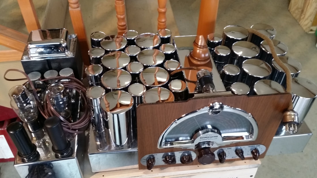
Masterpiece VI from 1937
BUT they are difficult to work on, even if you had the tools and schematic. Each one was somewhat custom made- in real terms. So the claim that each radio was built specifically for each buyer might actually be true AND an impediment to restoration today. (Much more on this coming in the next post)
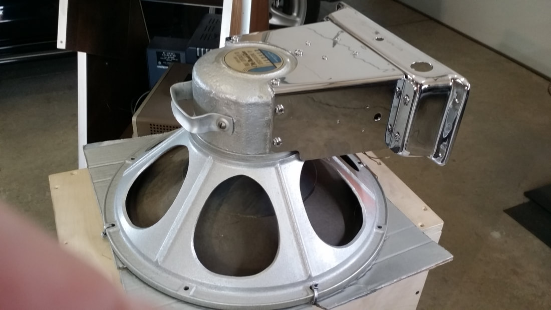
Sadly, not many were made. I'm sure that the price had a lot to do with that. Similarly, their price today has kept them out of most collections. Worse yet, they became well known for the hi-fidelity of their components. Unlike most radios of the time, a cabinet was optional so a complete radio consists of the tuner/pre-amp (above), a power supply/audio amp (below) and a massive, dual field coil, 18 inch Jensen pedestal speaker (2nd below). Today a complete radio might sell for around $6000.00 with or without a cabinet. Each of the components can be sold separately today (a boon for pickers on Pay-Bay). Where a nice unrestored receiver might go for around $1000, an amplifier can sell for nearly that much alone. The real problem has been that overseas demand has driven the price of the Jensen Super-Giant to ridiculous levels as high as $7000 in the recent past - around $3000 to $4000 today.
BUT they are difficult to work on, even if you had the tools and schematic. Each one was somewhat custom made- in real terms. So the claim that each radio was built specifically for each buyer might actually be true AND an impediment to restoration today. (Much more on this coming in the next post)
Sadly, not many were made. I'm sure that the price had a lot to do with that. Similarly, their price today has kept them out of most collections. Worse yet, they became well known for the hi-fidelity of their components. Unlike most radios of the time, a cabinet was optional so a complete radio consists of the tuner/pre-amp (above), a power supply/audio amp (below) and a massive, dual field coil, 18 inch Jensen pedestal speaker (2nd below). Today a complete radio might sell for around $6000.00 with or without a cabinet. Each of the components can be sold separately today (a boon for pickers on Pay-Bay). Where a nice unrestored receiver might go for around $1000, an amplifier can sell for nearly that much alone. The real problem has been that overseas demand has driven the price of the Jensen Super-Giant to ridiculous levels as high as $7000 in the recent past - around $3000 to $4000 today.
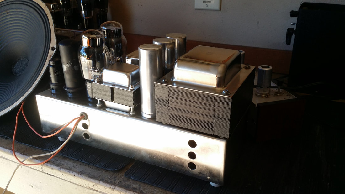
.Amplifier/ power supply
For that kind of money, it is hard for even a dedicated radio collector to resist selling the speaker and, unfortunately that is what has happened to many of these . So, today, it has become common to find a Masterpiece receiver alone in its cabinet with the speaker and amp long gone to Asia.
The receiver chassis is still worth having, but, all of the cool functions and wonderful tone can only be imagined. Though not absolutely unique, finding a substitute for the missing speaker is always a compromise in both quality and reduces the value of the radio as a collectors item.
The receiver chassis is still worth having, but, all of the cool functions and wonderful tone can only be imagined. Though not absolutely unique, finding a substitute for the missing speaker is always a compromise in both quality and reduces the value of the radio as a collectors item.
Fortunately, I have just completed the restoration of a collection of McMurdo Masterpieces and there were a few parts left over. No there weren't any 18" speakers (though I have purchased one from the collection) but there was one, sad, rusty MCMV amp chassis and a single filter choke, It seems that someone had replaced the power transformer with a smaller, unsuitable unit and, subsequently gave up on the project after it overheated evidenced by visible melted insulation on the primary wires.
I have long thought about building a power supply/amp suitable for running the many orphaned Masterpieces. I considered using a Scott 800B PS/amp. It could work. Or I could start with a brand new chassis. This would be a lot of work. It seemed easier to use the MSMV amp chassis that I already had.
After a few days of grinding and polishing my arthritis was protesting loudly. Maybe a new chassis would have been easier. But now that the rust and pitting was gone, I needed to make sure that it did not rust again. I considered gloss black paint. It would look nice but not very original for a radio known for CHROME (!). Well, I won't mess with chrome - too toxic. But nickel plate seemed like a good idea. It could be chromed later - if it just had to be done. So that is what I did.
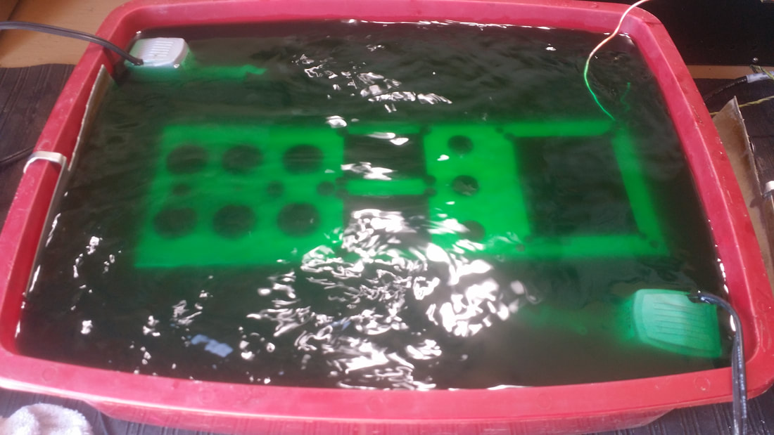
MSMV amp in the nickel plating bath
A nickel plated chassis can be polished to nearly the look of chrome. There is a slight color difference. Chrome is more blue-ish. I wasn't going to that extreme. The way it came out, a lay-person might think it was chrome anyway unless it was sitting beside a chromed piece. I was happy- enough. And I did not have to cut out all of those holes.
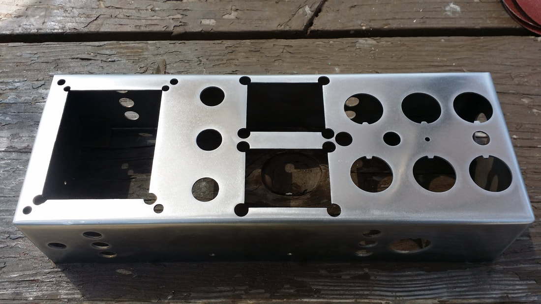
Bare MSMV amp chassis after plating.
SO NOW WHAT? Having only the single filter choke and the tube sockets ment that this was going to be a custom assembly any way you looked at it. Then I had an idea - What about a universal PS/amp capable of driving any natural magnet speaker. The thought of not being constrained by the normal factory-look restoration intrigued me. "Let's take it one step further - how about a PS/amp that could run either a MSMV OR a MSMVI? So it was to be!
Now all that I needed was a pile of hard-to-find parts. I went through my transformer pile focusing on several REALLY BIG ones removed from 1960's electronic (tube) organs. I never thought that I would use one of these. They were over-kill for even the largest 30's radios or even stereo amp projects. I'm glad that I kept them.
The PS uses 2, 5Z3 rectifiers, so the trans must provide at least 6A at 5V and the DC requirement was for at least 300ma at about 450V. There was also the requirement to heat 18, 300ma tubes. I needed both hands to lift this one!
Besides all of the little parts, I needed another choke, a interstage trans for the MSMVI input and an output trans capable of handling the push-pull 6L6s. And I needed to hit the target voltage for the receiver, around 340V under load, without having the 2 original field coils in the circuit. PLUS avoid the hum caused by removing said field coils which were also used for filtering. Skill - or luck, either would be fine with me.
Here is a list of the objectives:
1. Start with a MSMV design
The MSMVI has the 2nd audio on the receiver chassis but the MSMV needs the 2 6C5s to drive the push-pull 6L6s .
2. Find the missing 2nd choke at about 10h 200ma
B+ for the output 6L6s is taken after the first choke. So the 2nd choke must be good for about 200ma.
3. Find an interstage transformer for the MSMVI input to the final audio stage.
The 2nd audio stage is on the receiver chassis so routing the signal through the V's 6C5s will produce too much gain/noise. Also the VI uses the interstage as part of the bass control, omitting it would also eliminate this control function. A 1:1 or a slight step-down will be best since additional voltage gain is unnecessary.
4. Add a suitable output trans
Since the original one is on the speaker on both the V and VI. 8 ohms would be best. Ours provides both 4 and 8 ohm secondary taps.
5. Increase the values of the filter caps to help compensate for the loss of the field coils.
I used a 10uf 630V film cap in the first position that originally was two .5uf at 400V in series resulting in a value of .2 (point 2) at 800V. They were probably trying to take it easy on the 2 rectifiers by using a small or no cap prior to the first choke. Then a 47uf 450V 105c electrolytic in both the 2nd and 3rd filter position. I wasn't sure whether I was going to need a resistor to drop B+ to the receiver to 340V at this point so if I had to add a resistor I thought I would add a 4th filter cap as well. Turns out that neither were needed.
6. Wire the original 6 pin speaker port/socket to accommodate the VI receiver
Since the FC speaker is not used the 6 pin plug is available to power a MSMVI the V uses the original socket.
7. Determine the best point to insert the audio from the interstage to the final amp.
The V application is as it originally was but I needed to inject the signal from the interstage at the grids of the 6L6s without affecting the output from the 6C5s too much. The interstage trans provides the inverted signal for the VI that was accomplished by the 6C5s on the V. The 6C5s are cap coupled to the grids by .1 (point 1) caps. I chose this point to inject the signal using .045 caps to try to prevent some of the loss that would occur by placing the transformer windings across the output of the 6C5s.
This worked great. I balanced the inputs by driving the amp with a stereo signal, R through the V port and L through the VI port to compare the levels. I reduced the value of R11(K) from 500K to 50K to compensate for a slight loss. This resistor is one of the "custom" parts to be covered in a later post.
This all could be made easier with a switch for V and VI but I did not want to have to remember to make the switch - or to look at it.
8. Use 1/2 of the transformer's 12V filament winding for the receiver and 1/2 for the amp (as was done on the organ (donor organ ;)
The receiver draws 16 or 18 X .300A or about 5A at 6.3V
9. Check for proper voltages and make adjustments.
The new power transformer delivered about 750V for the B+ where as the original delivered about 1000V. This is OK - actually required since the resistance across the field coils will be missing. Some compensation can be made in the filter chokes. On the V they are both the same, about 10h and 50 ohms each but on the VI the 2nd one is about 10h but 125 ohms. Which explains some of the differences in the V and VI speaker field coils (again more later). The only adjustment that was needed was on the cathode resistor for the 6L6s. At the stated value of 250ohms 20W (these are almost always 10W and often show signs of overheating) we had 39V on the cathodes. So it was a good time to upgrade to a 25W 180 ohm unit which gave us about 26V on the cathodes and improved bass response too.
10. Find a place to put all of the "extra" components.
I extended the mounting bolts for the chokes so that the output trans and interstage trans could be mounted, though I did plat the bell for the output trans and mounted it on top with the 2nd choke being relocated below. There are good reasons for doing this, also to be covered later.
11. Upgrade wire. Use 600V neoprene for a "original" look but much better service. Upgrade fuse holder since I didn't have an original. Clean up the original layout for best wire routs. Add a convenient terminal strip for the various B+ voltages. A good place to terminate the chokes and caps and take measurements.
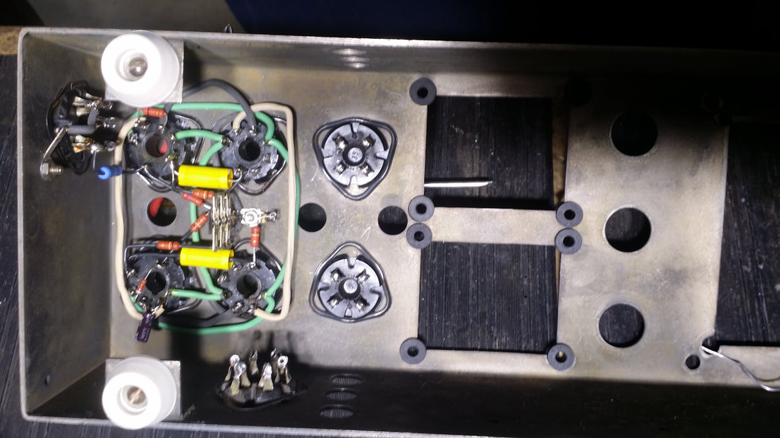
Underside with everything mounted. The three wires coming out the top are the speaker out, 4 ohms and 8 ohms. I have not provided an on off sw yet.
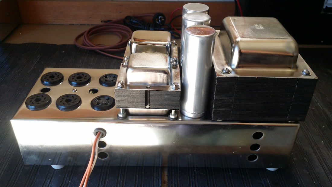
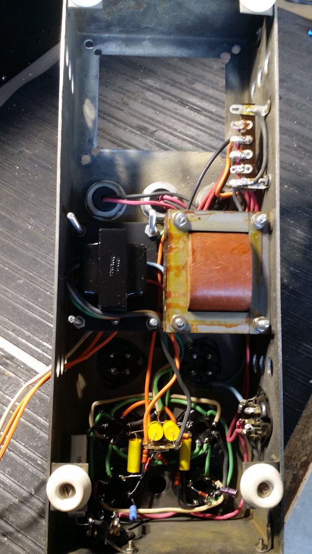
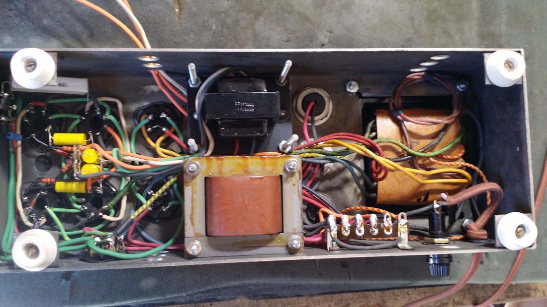
Top side. Note the output trans in place of the original 2nd choke.
Above is a demo using a VI receiver chassis. The VOM is monitoring the B+/screen voltage to the receiver chassis. The B+ to the 6L6s is about 420V.
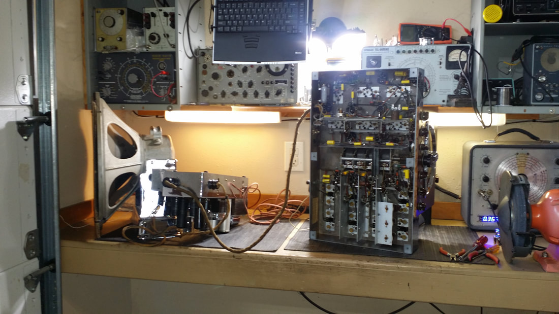
I still need a bigger bench - - -
Russ
Russ

 RSS Feed