
I stated somewhere, probably more than once, that my interests include early radios up to 1942 and later Hi-Fi from around 1955 to 1979.
Why, you may ask, do I exclude the decade between 1945 and 1955? Cabinets, those rectangular, featureless cubes with doors that degraded further with the "blond", yellow and whitewashed finishes that continued into the 60s.
The problem, for me, is two fold. First, these designs tend to hog floor space. Second, unless you design a room around them, these consoles don't fit well with most décor. Or even more simply put, they are just not to my taste. I know that my feelings are not universal, but demand and prices over the years do indicate considerable sympathy. I will have to concede that after considerable resistance, a 3 channel Motorola has been added to the display - and I kind of' like it.
Unfortunately there were some great radios hidden inside of those cabinets. Scott and Meissner were just two of the high end manufacturers that followed this trend. They had to. It was the style of the time.
Fisher consoles are often stripped of their tuners to be installed in cabinets like those that became popular in the 60s and 70s. I suppose that this is preferable to losing the whole console to the land fill, but, one day (maybe today) the original cabinet will be missed.
So when recently I was given a number of these late 40s, upper-end radios, I simply stashed them in the parts room and moved on to the good stuff. I suppose that fate and my desire to preserve history collided when it became necessary to clear out the parts room - or put a warning sign on the door - Enter at Your Own Risk!
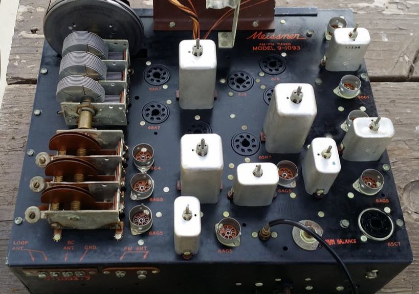
Meissner 9-1093-7 AM and FM Tuner
Among these radios was the Scott 510 discussed below and a Scott 800 that I have not addressed yet. But the ones that interested me most were the Meissners. There was quite a collection - none were complete and none had a cabinet.
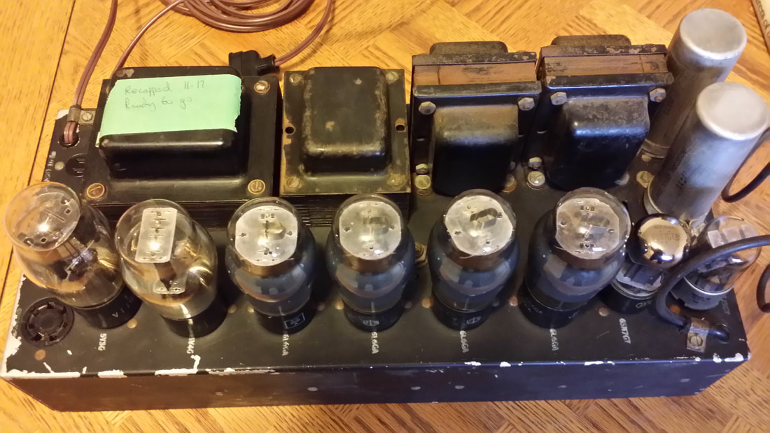
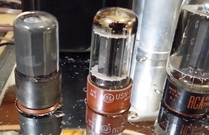
First there was the 2961 amp - REAL radio candy from 1947! I just could not ignore this PS/amp with push-pull parallel 6L6GA output tubes. Turns out the 6L6s are wired for triode operation which reduces the power output considerably (as compared to pentode operation). This amp/dual power supply was the heart of a 2961 tube radio - I wish that I had the rest of it.
Since I had neither the original 2961 receiver nor the amps for the 9-1093-7 and 9-1093, I built an adaptor to use them in combination as well as with a 9-1091C receiver (later).
At this point I will confess that the original configuration of the 9-1093 had only (ONLY!) 24 tubes, but what the heck. Here is a video. The original coaxial speaker and OP transformer are also missing so I had to adapt -
Meissner 9-1093-7 and 2961 (26 tubes)
The 1093-7 chassis was in the best shape of all of them with the black finish and red lettered labels remarkably intact. Yet it also needed the most work.
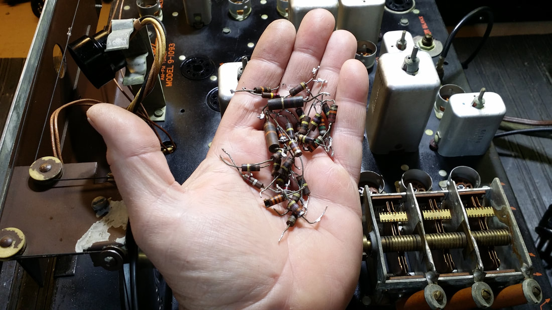
Along with the standard restuffing of paper and electrolytic capacitors, this unit also had about half of the carbon resistors way out of tolerance. I was able to replace all of the resistors with NOS carbon comp resistor from my parts inventory. This kept the bottom side of the chassis looking original as well as the top side.
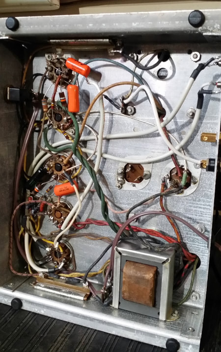
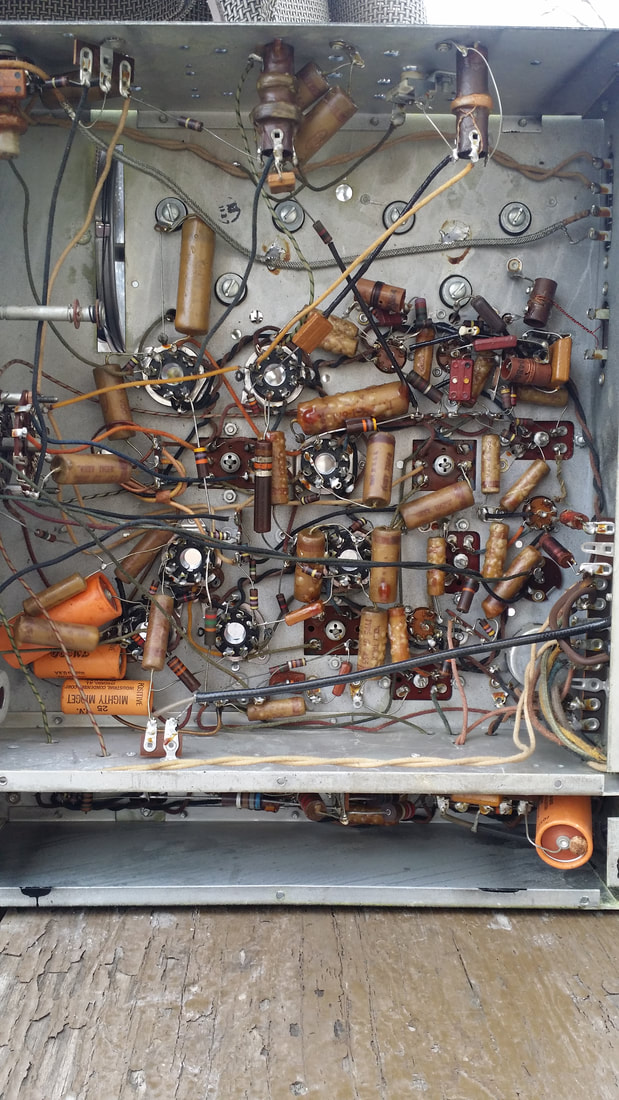 | 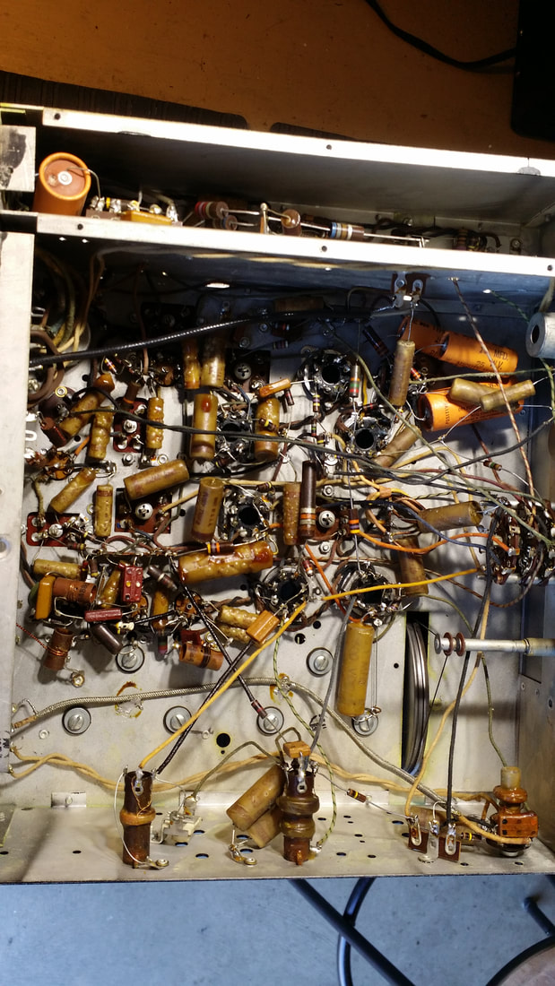 |
Before and after of chassis underside
During the parts replacement all eyelets are cleaned and the original mechanical contact is restored prior to soldering. This keep the eyelets and contact strips from "bulking up" with old solder and the old component wire ends also maintaining the original look and reducing the chance of intermittent contacts.
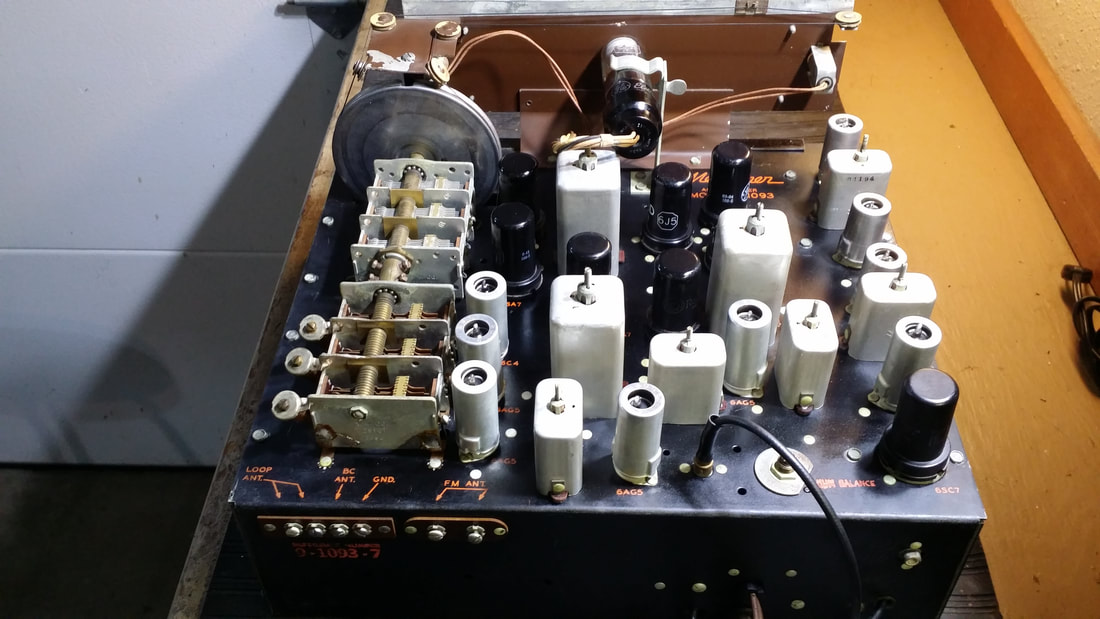
You might note the -7 on this model number. This one is the only reference to that suffix that I have found. The other version is just 9-1093. I have one of each and there are at least 3 very significant differences.
The -7 version has an on-board preamp tube for phono mounted at the end of the FM circuit and inside of the area that shields the last IF, 2 limiters and the discriminator. The other version has a hole/cover in the chassis but uses a separate pre-amp module with 6V and B+ coming from the main chassis. Interesting that the pre-amp must be plugged in in both cases to an RCA input connector.
The -7 version also has the nice black paint and the controls are mounted directly to the front of the chassis rather than being spaced back several inches in the other version.
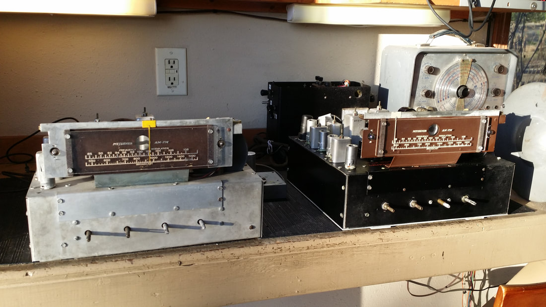
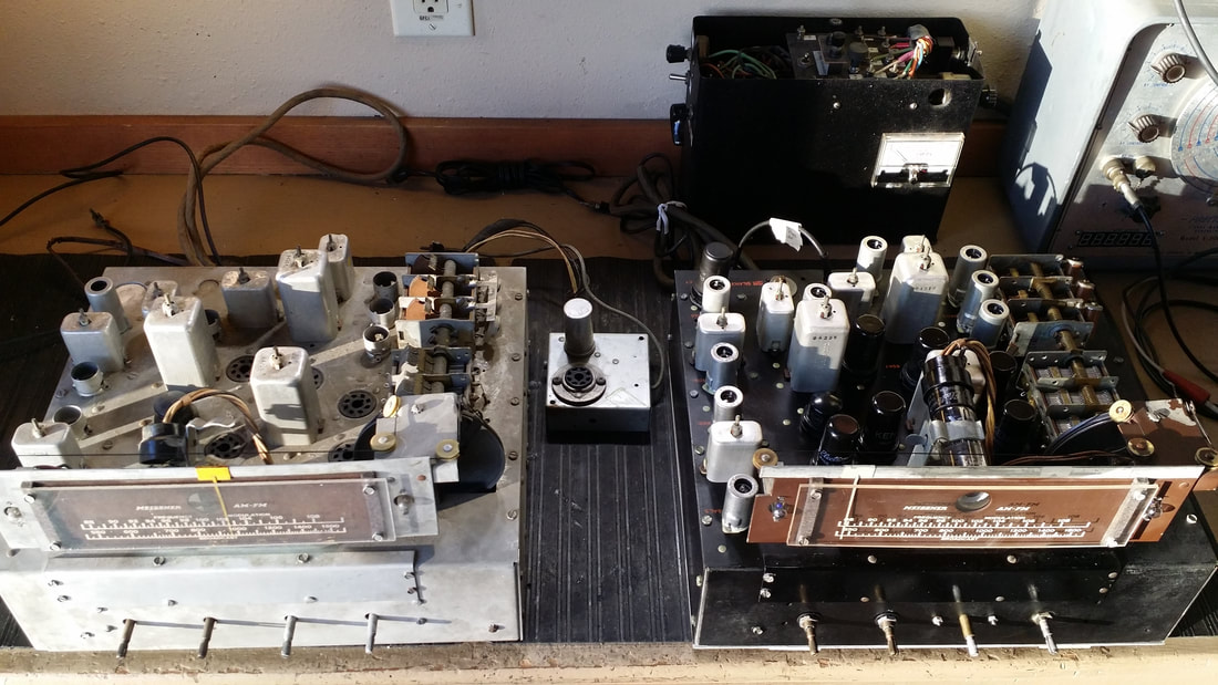
Above, notice the stand-off for the controls in the non-7 version and in the center picture the separate pre-amp module
Meissner 9-1091C
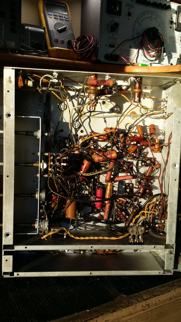
This is another AM FM (mono) chassis from about the same period. It has somewhat more versatility as compared to the 9-1093 since it has it's own power supply and push-pull 6J5s capable of driving almost any amplifier. But, it still does require a separate amplifier chassis. This radio has 17 tubes including a 6U5 eye tube to display signal strength. Like the 9-1093, AM and FM reception and audio quality are very good.
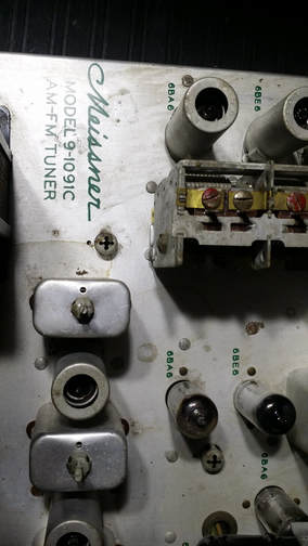
Meissner 9-1091C Tuner
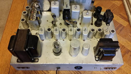
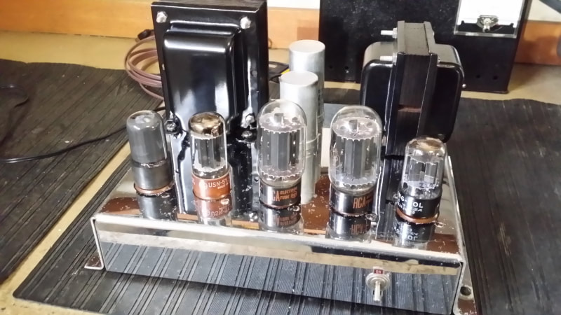
Meissner 2961 Power Supply/Amp
This 2961 amp uses push-pull-parallel 6L6GA wired as Triodes. It has 2 rectifiers. The 5Y3G supplies B+ for the tuner chassis and a 5V4G provides B+ for this chassis. There is a separate filament transformer.
One of the features of this amp that is notable is the socketed filter capacitors, one for each of the B+ supplies. These caps use a 4 pin socket like the one used for an 80 or 2A3 tube. They are secured by a clamp. This sure would have made servicing the filters easier. They could have been changed out every couple of years to avoid failures.
One of the features of this amp that is notable is the socketed filter capacitors, one for each of the B+ supplies. These caps use a 4 pin socket like the one used for an 80 or 2A3 tube. They are secured by a clamp. This sure would have made servicing the filters easier. They could have been changed out every couple of years to avoid failures.
This collection of Meissner radios also includes a Signal-Shifter EX ( low power CW transmitter ) and a much smaller kit radio. I will post any updates on those as I get to them.
It seems that many radios were sold as kits or replacement chassis for a cabinet that a customer already owned. This is consistent with the company's other offerings of quality OEM and replacement parts. Some were sold under the name Maguire. You might want to do more research under the name Thordarson-Meissner / Mt. Carmel, Illinois. Thordarson is still in business. (Thanks Ron)
To conclude, this series of radios, especially the large chassis with FM, were very high quality only lacking the chrome to be compared with the very high end radios of the time. If you happen upon one of these radios and have never heard of, or seen one, you are not alone. If the price is right, you might want to add it to your collection.

 RSS Feed