
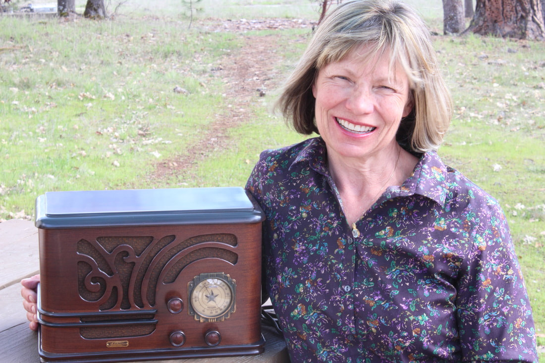
Smile
Getting old. My time spent leaning over the work bench has become more limited. So I have to chose my projects more carefully, even when people try to give me "stuff to fix".
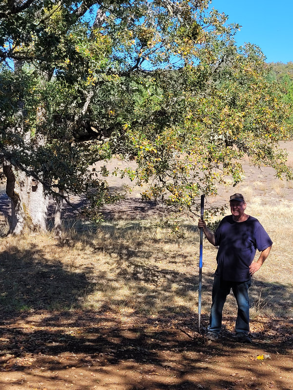
There is still the tree farm to take care of and with the weather changes, 117deg temperatures, drought and or, floods and fire prevention/control, there is still a lot to do. Quite a few large trees have died - free firewood, but that chain saw is getting heavy.
Below are pictures from projects, recently completed, for which I have not made posts. If you would like me to give further details about any of them , comment at the bottom. I might be able to go into further detail and pics. I highly recommend the OTL (output transformer-less) amp. It's performance is just amazing.
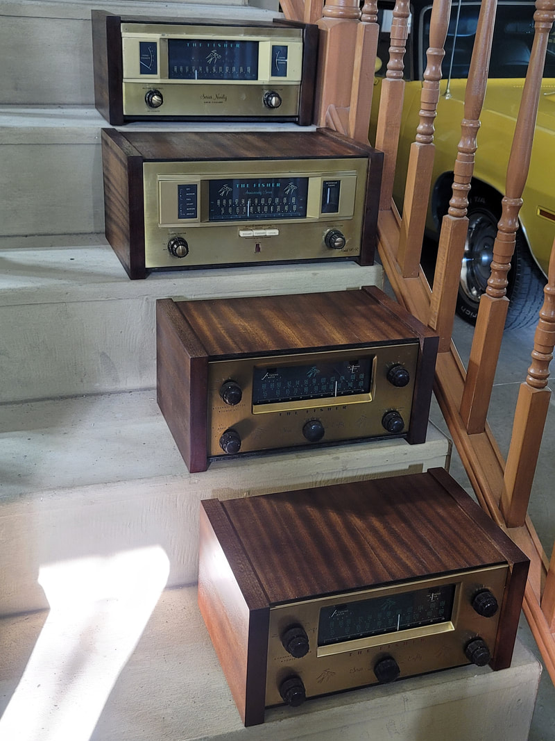
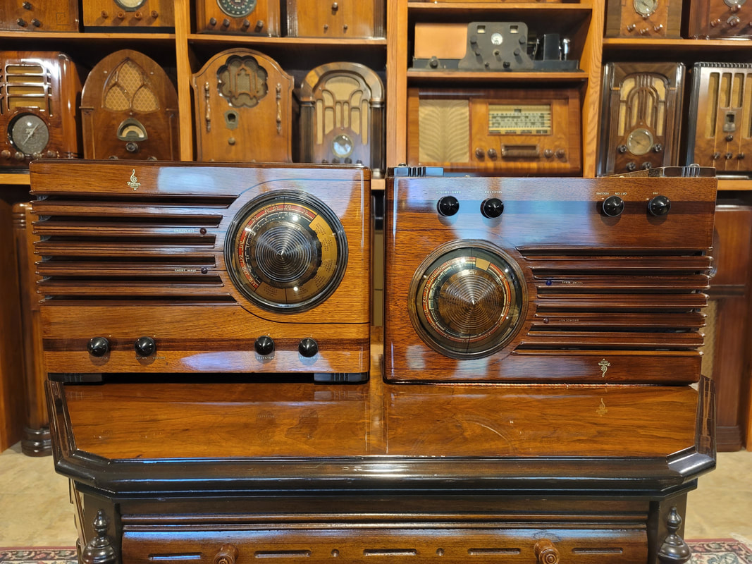
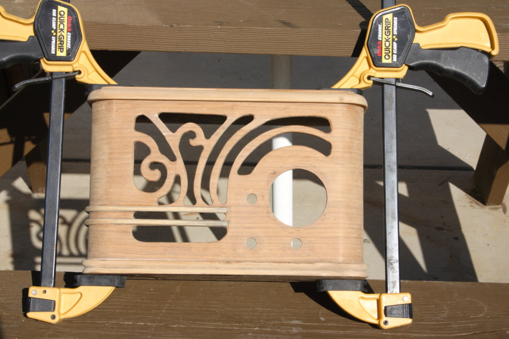
What to do with all of these nice Fisher tuner/preamps with no cabinets. Not enough room to equip the original consoles and the smaller/component cabinets are hard to find, expensive and kind of ugly (IMO).
So I set up a production line and made a few (8). The sides are solid 1" mahogany that I milled from raw planks, which I could get and could get at a reasonable price - just more work and a lot of chips. The tops are mahogany veneer on Baltic birch plywood and they will slide out the back so the radio can be serviced (tubes) without removing the cabinet.
So I set up a production line and made a few (8). The sides are solid 1" mahogany that I milled from raw planks, which I could get and could get at a reasonable price - just more work and a lot of chips. The tops are mahogany veneer on Baltic birch plywood and they will slide out the back so the radio can be serviced (tubes) without removing the cabinet.
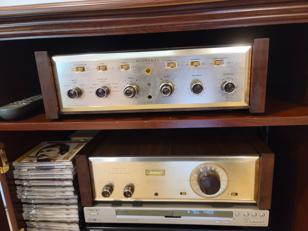
Scott amp and tuner, also in new matching cabinets
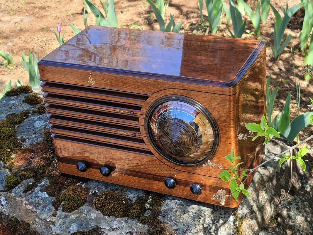
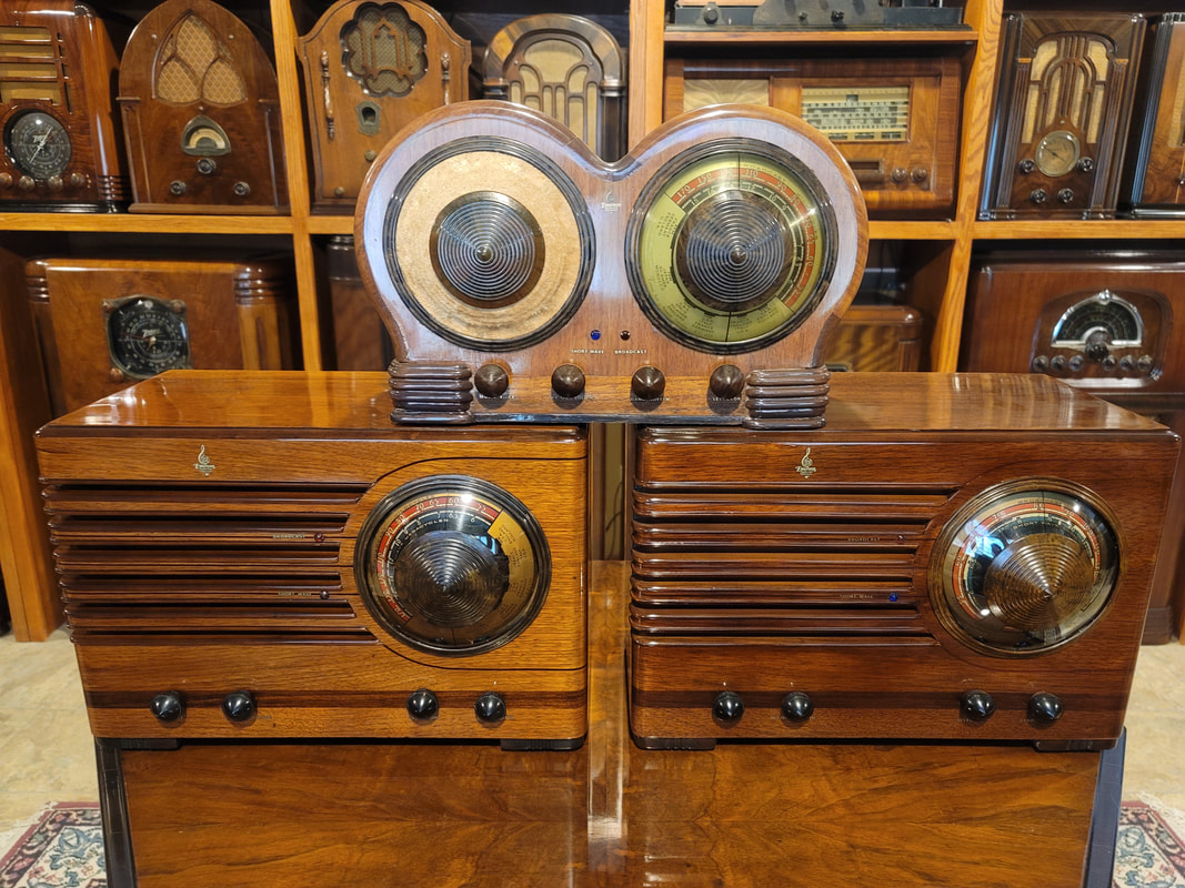
EMERSONS
CV-295 Bird's eye maple cabinet
CV-295 Bird's eye maple cabinet
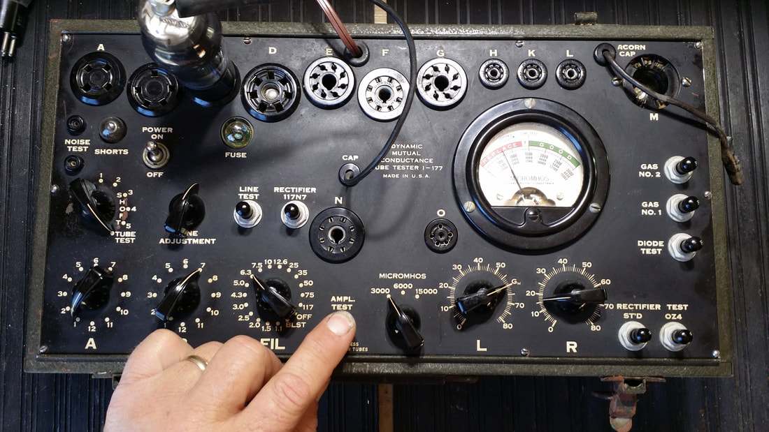
BW-231, sometimes known as "half of a Mae West".
Attempting to resolve imbalance.
Hum---
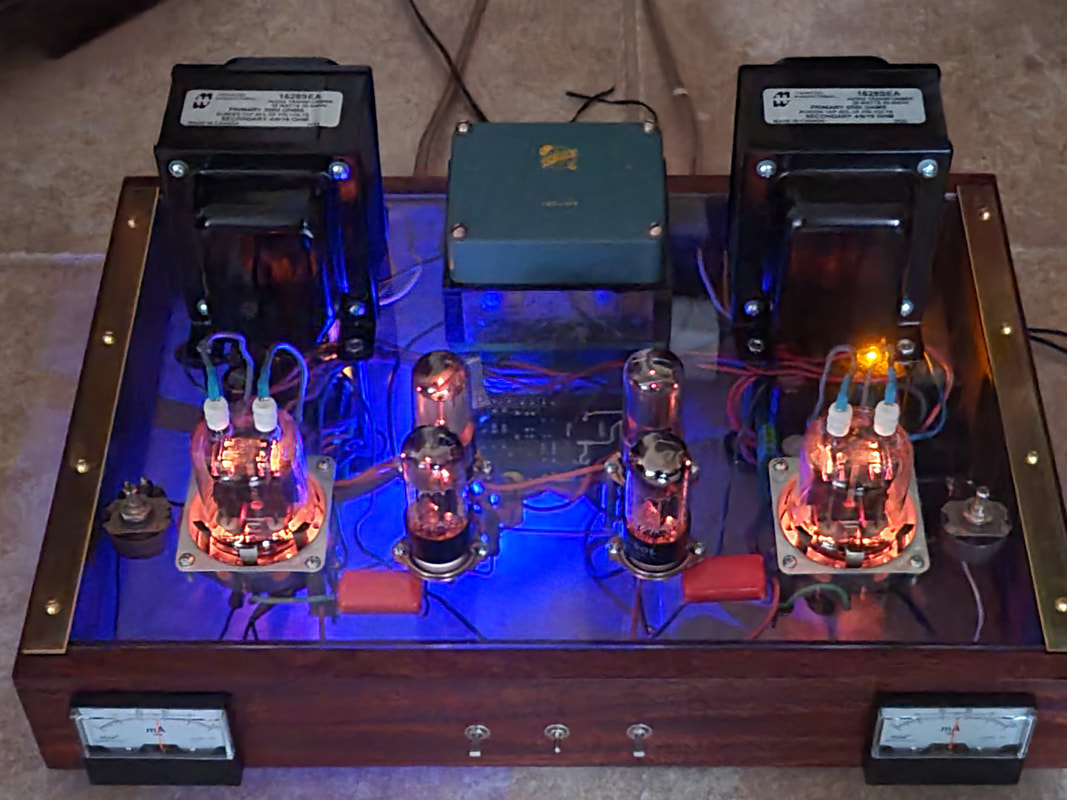
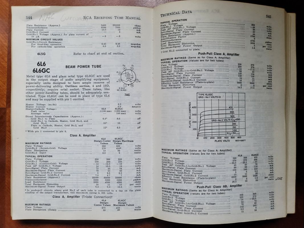
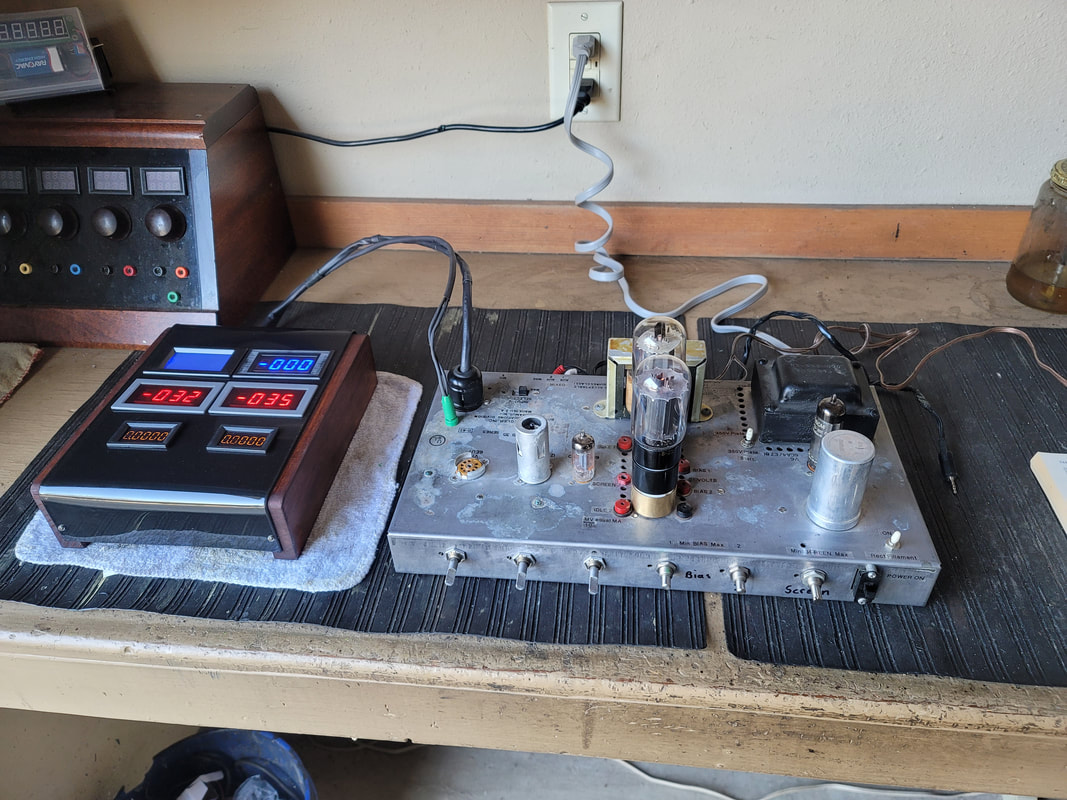
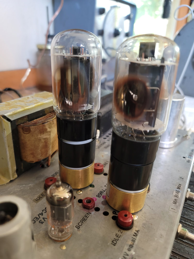
829B single ended stereo amp.
I had heard that these are not audio tubes.
I had heard that these are not audio tubes.
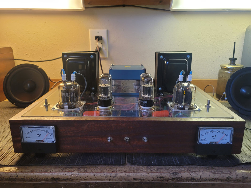
Showing an idle current of about 90 ma. per channel. That is 45ma for each parallel pentode (2 per 829B). I later reduced the idle current to 60 ma @ 310V. It will run in either ultra linear or pentode mode.
Yes, it is built on a sheet of plastic. Very quiet - until you turn it up, with no hum from the regulated power supplies.
Yes, it is built on a sheet of plastic. Very quiet - until you turn it up, with no hum from the regulated power supplies.
Somebody help me up - -
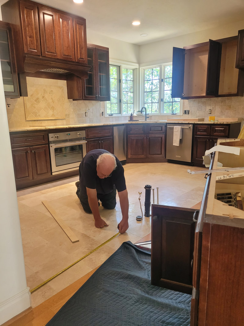
New kitchen.
New kitchen.
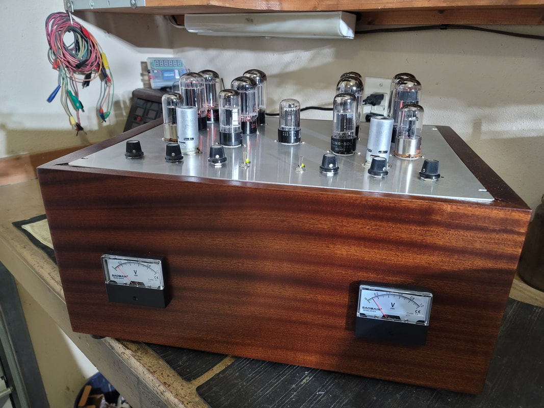
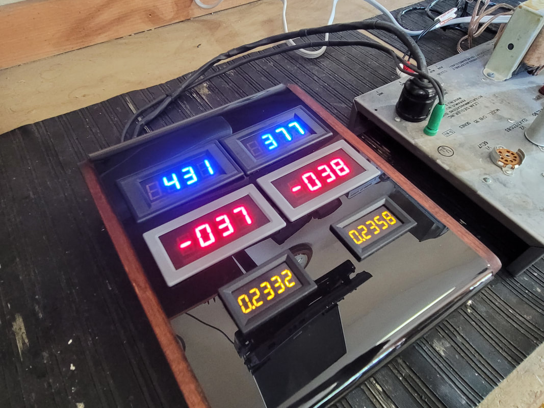
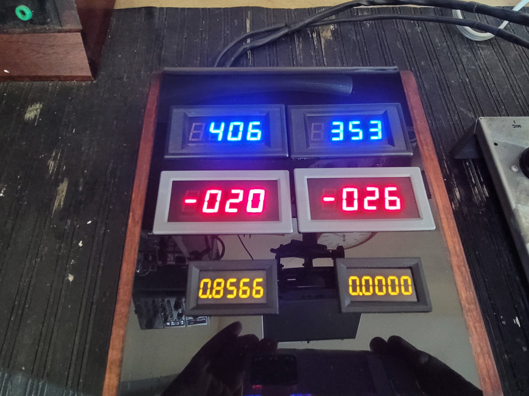
Now for something entirely different - OTL Circletron
When I went to school (EE. Rolla MO.), what I REALLY wanted to learn, was how to build my own amplifiers - well - and to get a job to pay for them. In the following 50 years, there was always something else to do. But I collected a lot of parts, like 6080 tubes (6AS7). A SUPER TRIODE, that is only used in power supplies (frowney face 😉). Yea, right!
When I went to school (EE. Rolla MO.), what I REALLY wanted to learn, was how to build my own amplifiers - well - and to get a job to pay for them. In the following 50 years, there was always something else to do. But I collected a lot of parts, like 6080 tubes (6AS7). A SUPER TRIODE, that is only used in power supplies (frowney face 😉). Yea, right!
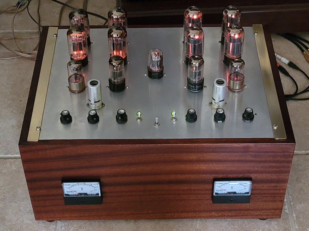
Idling at 125 ma per 1/2 of 1 channel (total X 4). Total peak current through both channels, about 2A. at 160V.
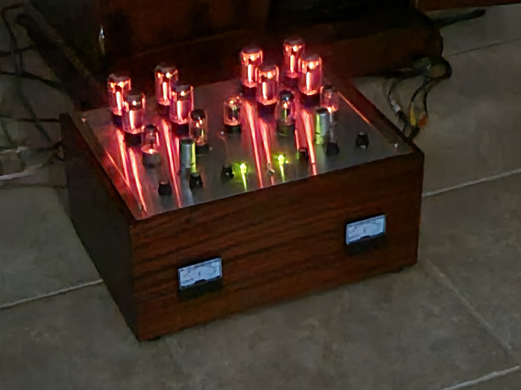
Smokin'!! (if you touch it). 10A @ 12V filament draw - only on the 8 finals (16 triodes). 28 triodes total, though 2 are unused (1/2 of the 12AX7s), and 2 regulating the Bias.
Also serves as emergency heater. Yes, it has a "warm" tone. Freq response from about 5hz to 100khz or more. It would go down to DC but I thought it would be better to prevent that from happening.
Also serves as emergency heater. Yes, it has a "warm" tone. Freq response from about 5hz to 100khz or more. It would go down to DC but I thought it would be better to prevent that from happening.
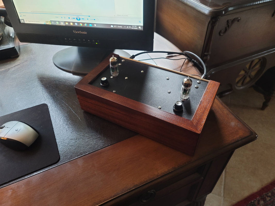
12B4 line Amp
I needed to get the signal from my music server across the room to the OTL amp. Though I ran all of the wire I thought I would need when the shop was built, the best I had here was 2 twisted pairs from an old S- video cable. Needed to boost the level to drop the noise floor and balance the line into the 12AX7 first stage of the amp. It also provides remote volume and balance with a slight loudness curve to compensate for losses.
AGAIN with the "these are not audio tubes" thing.
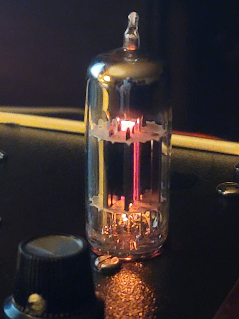
12B4 triode.

Takelma People projectile point, 200 - 1000 years B.P.,C.E.
As a result of the clearing needed to control wildfire, weeds were removed and the ground was exposed. We began to find arrowheads around the house. Compared to those I found as a kid in MO these are tiny and very intricately carved- and mostly broken, but still very cool.
As a result of the clearing needed to control wildfire, weeds were removed and the ground was exposed. We began to find arrowheads around the house. Compared to those I found as a kid in MO these are tiny and very intricately carved- and mostly broken, but still very cool.
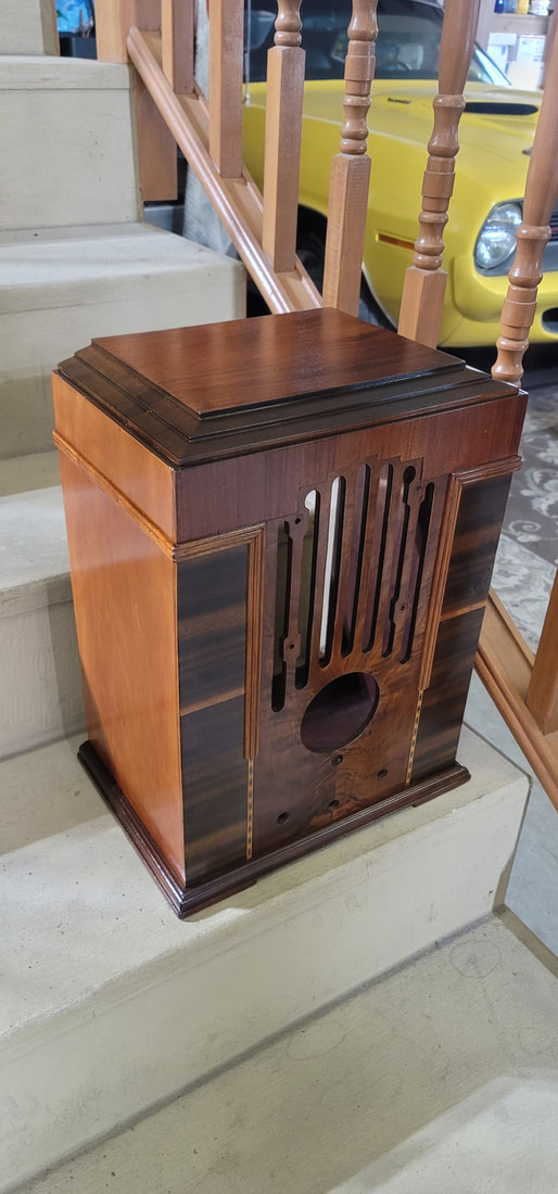
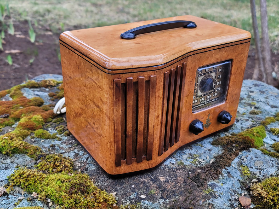
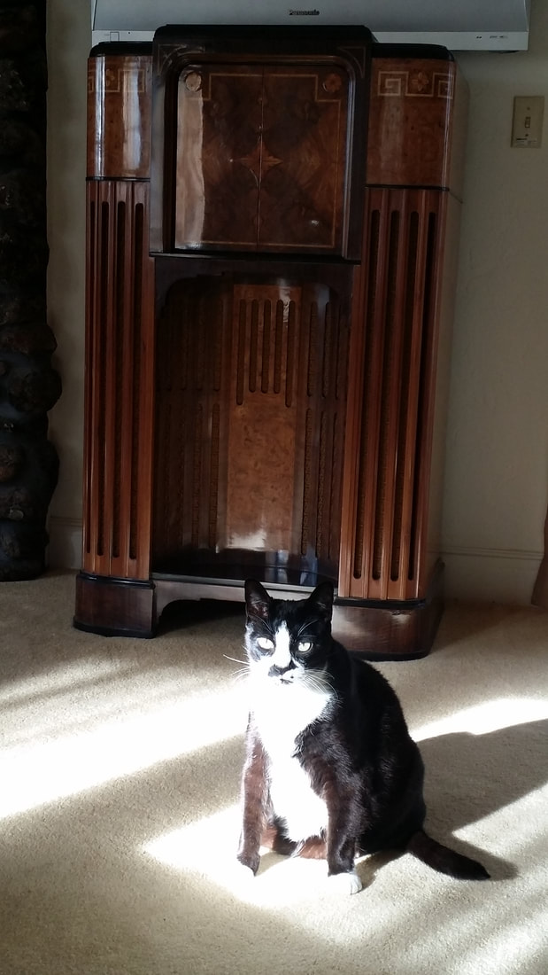
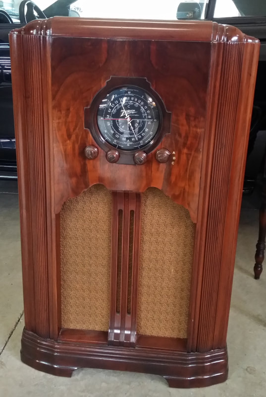
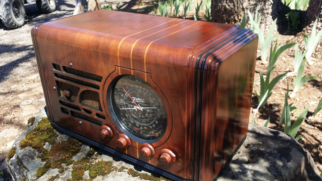
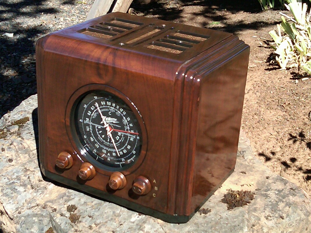
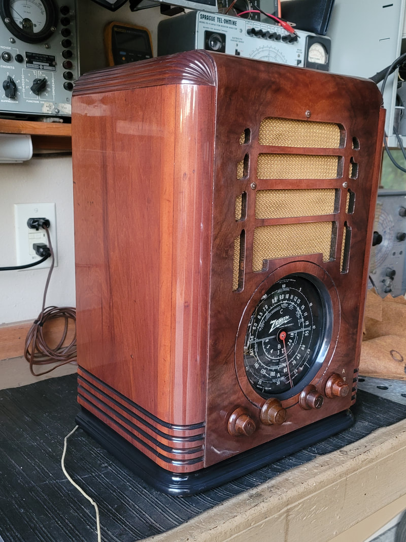
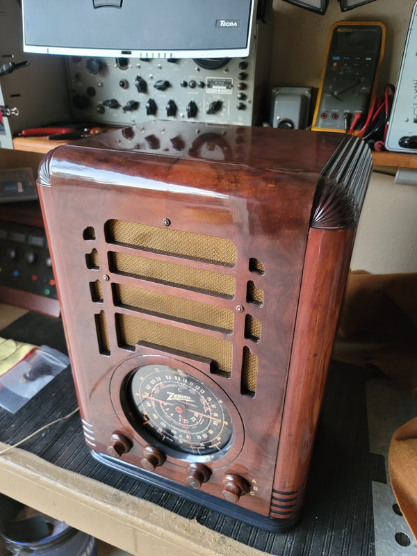
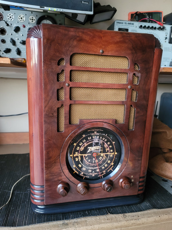
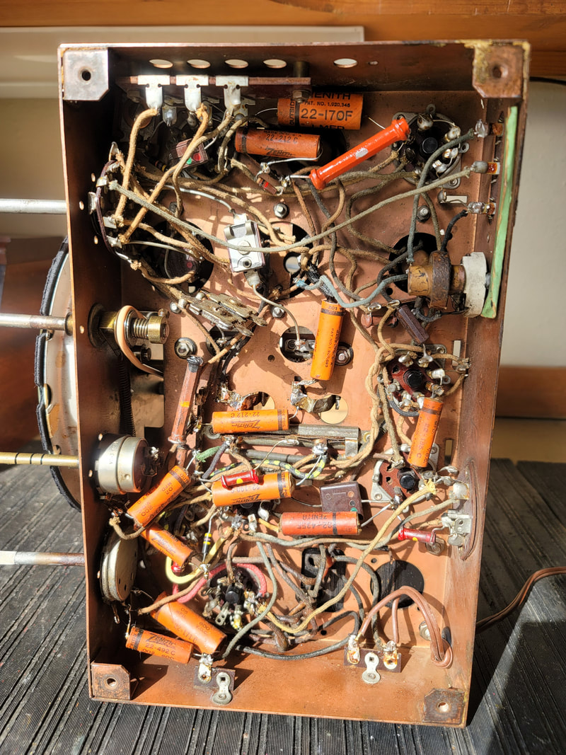
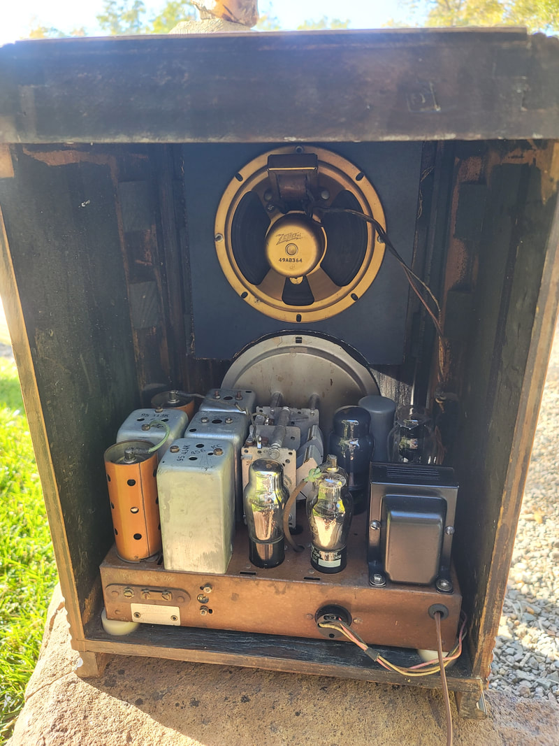
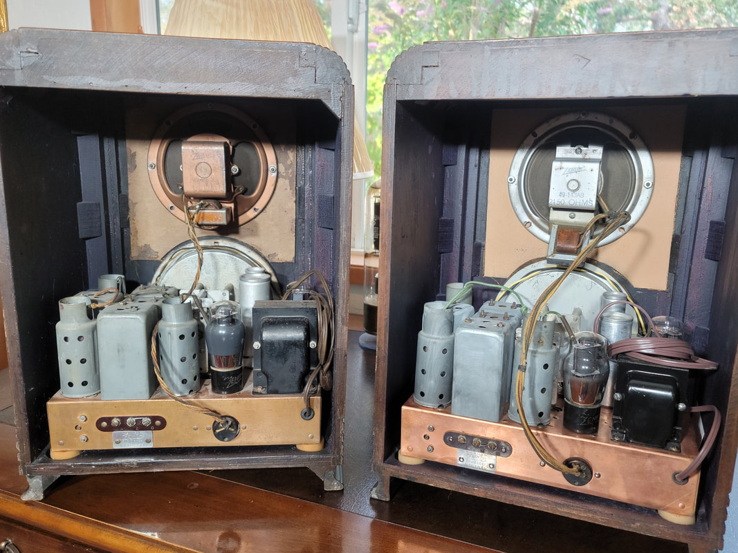
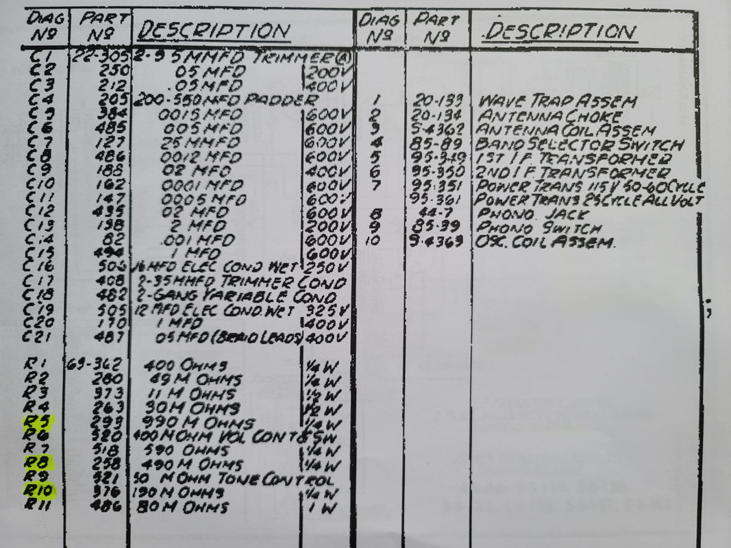
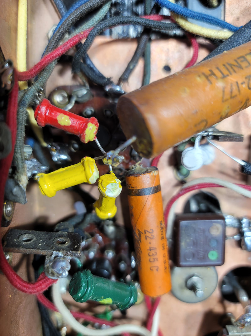
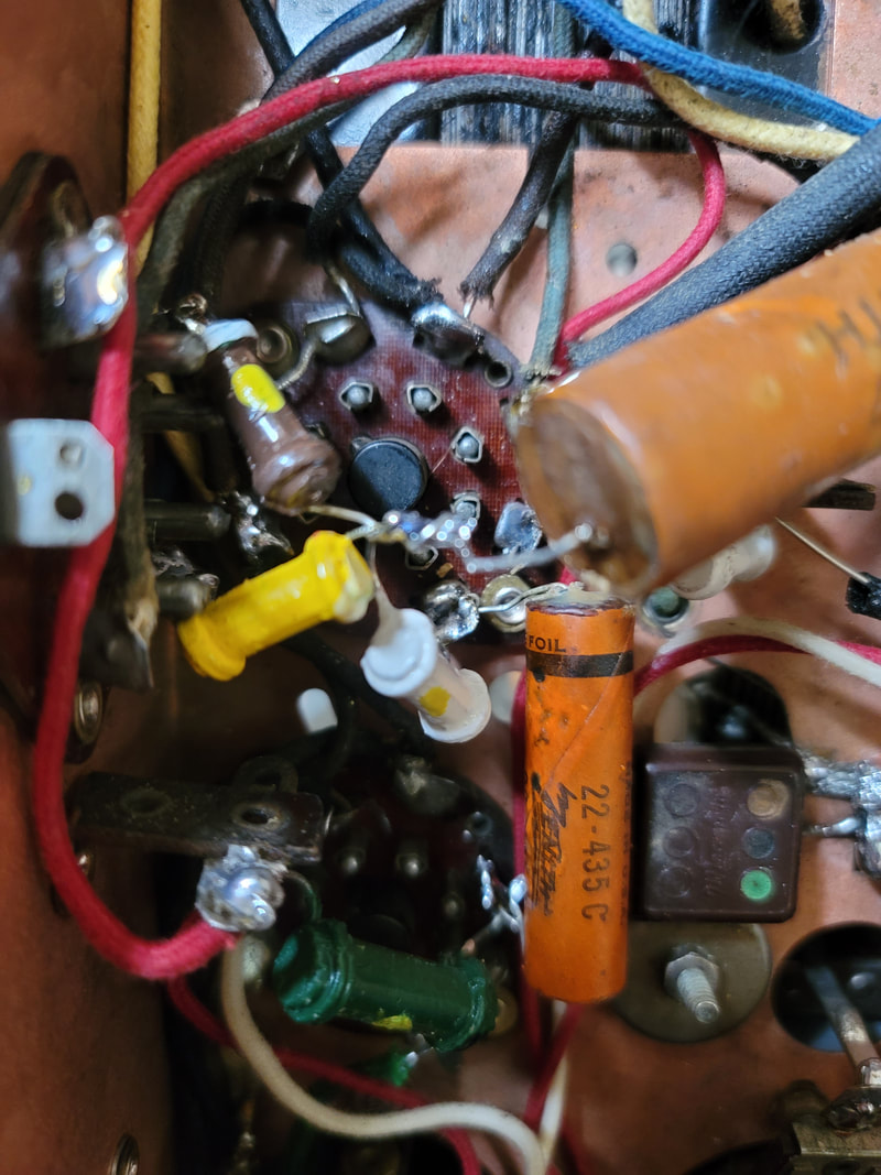
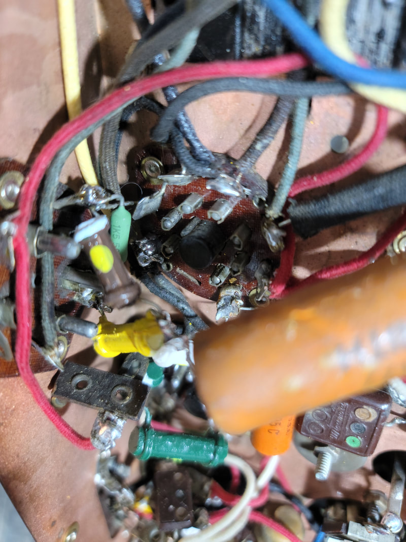
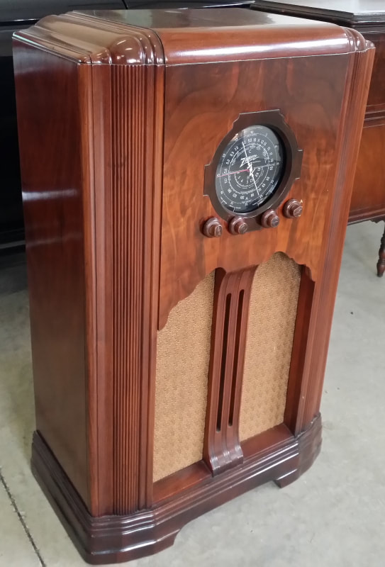
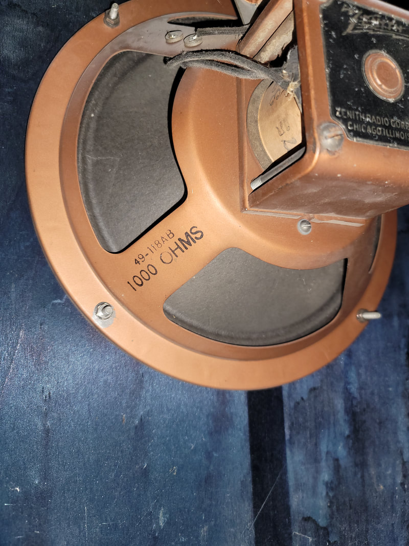
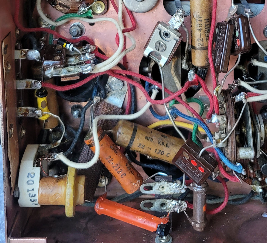
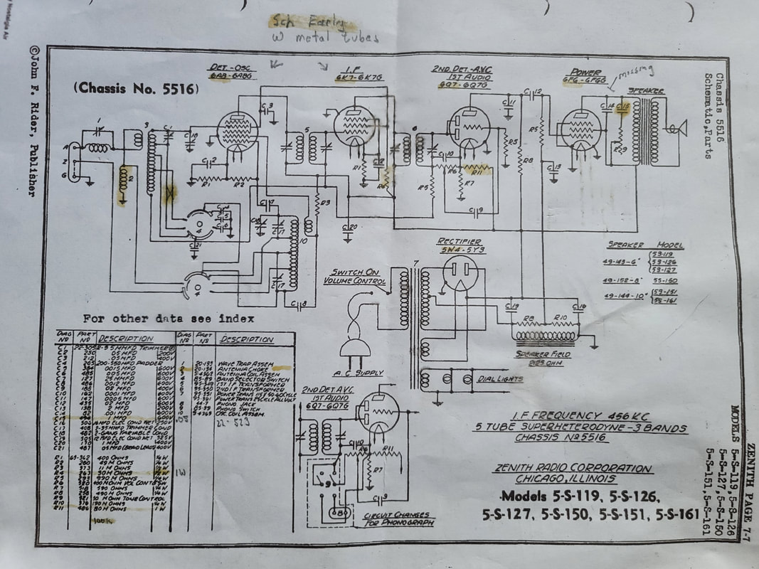
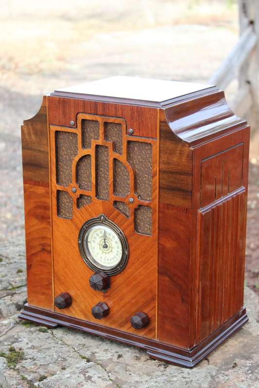
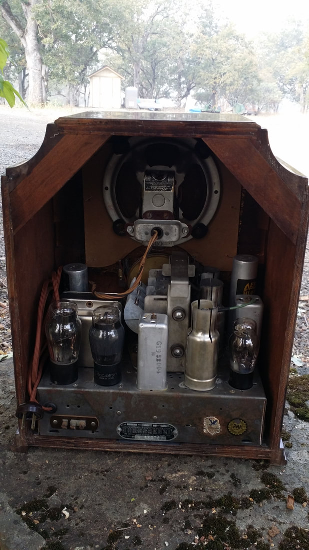
Zenith 808 from 1935 (Stewart Warner)., given to me by Bill Meyer, station manager/DJ at KMED Medford. (Now FM only)
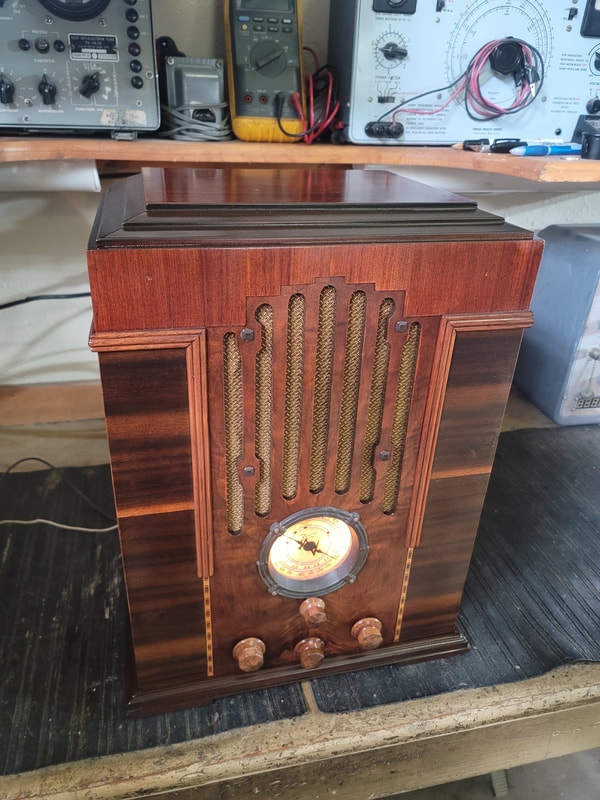
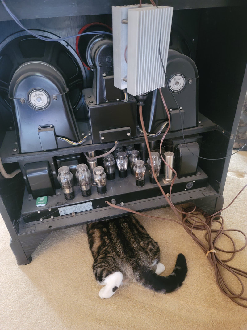
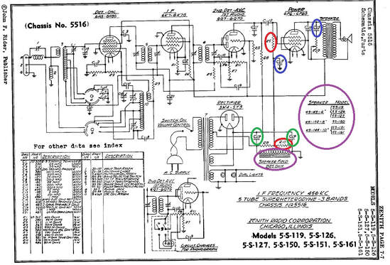
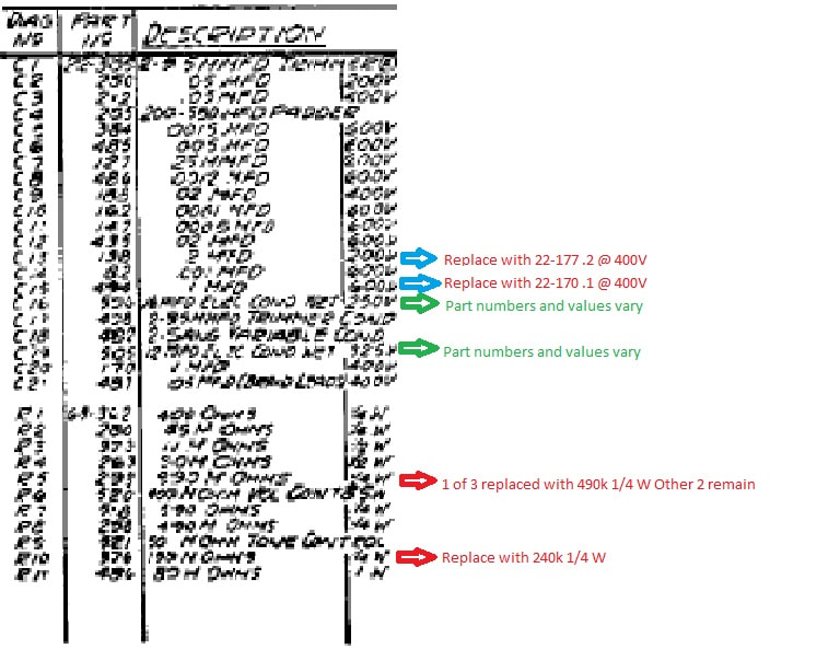
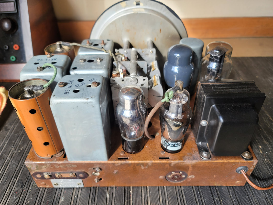
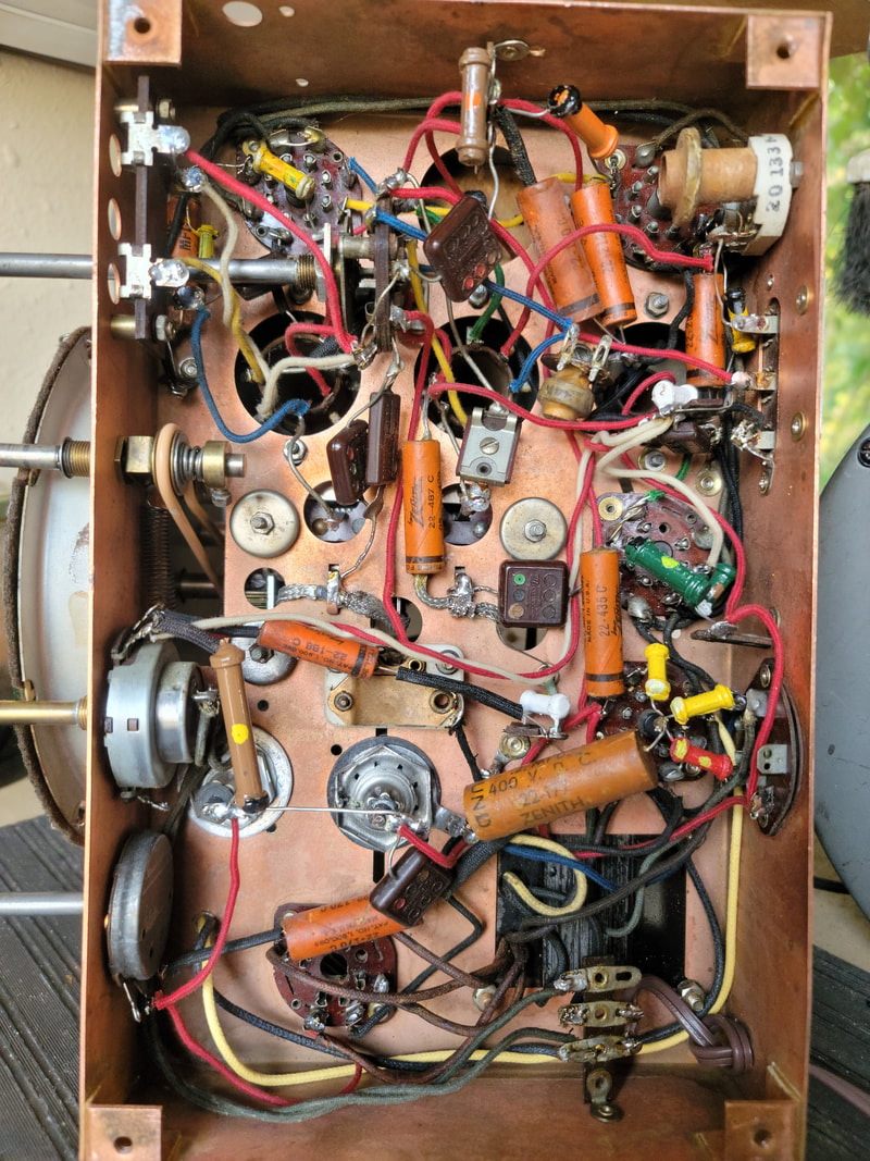
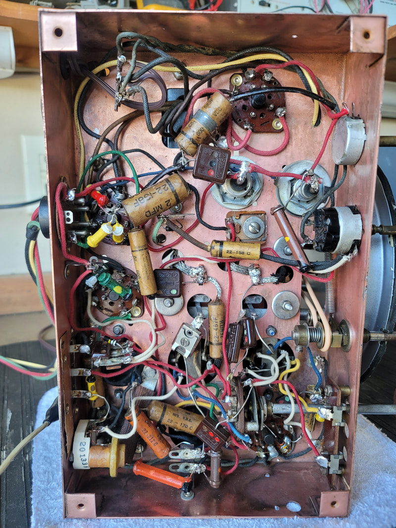
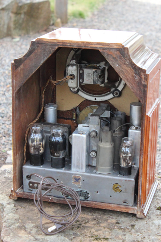
All of the caps and most of the resistors needed to be replaced.
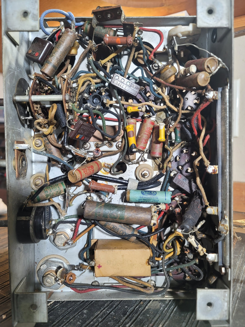
As Found
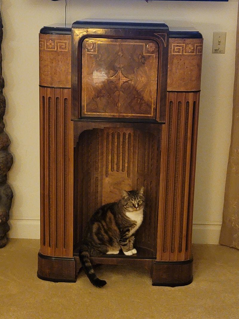
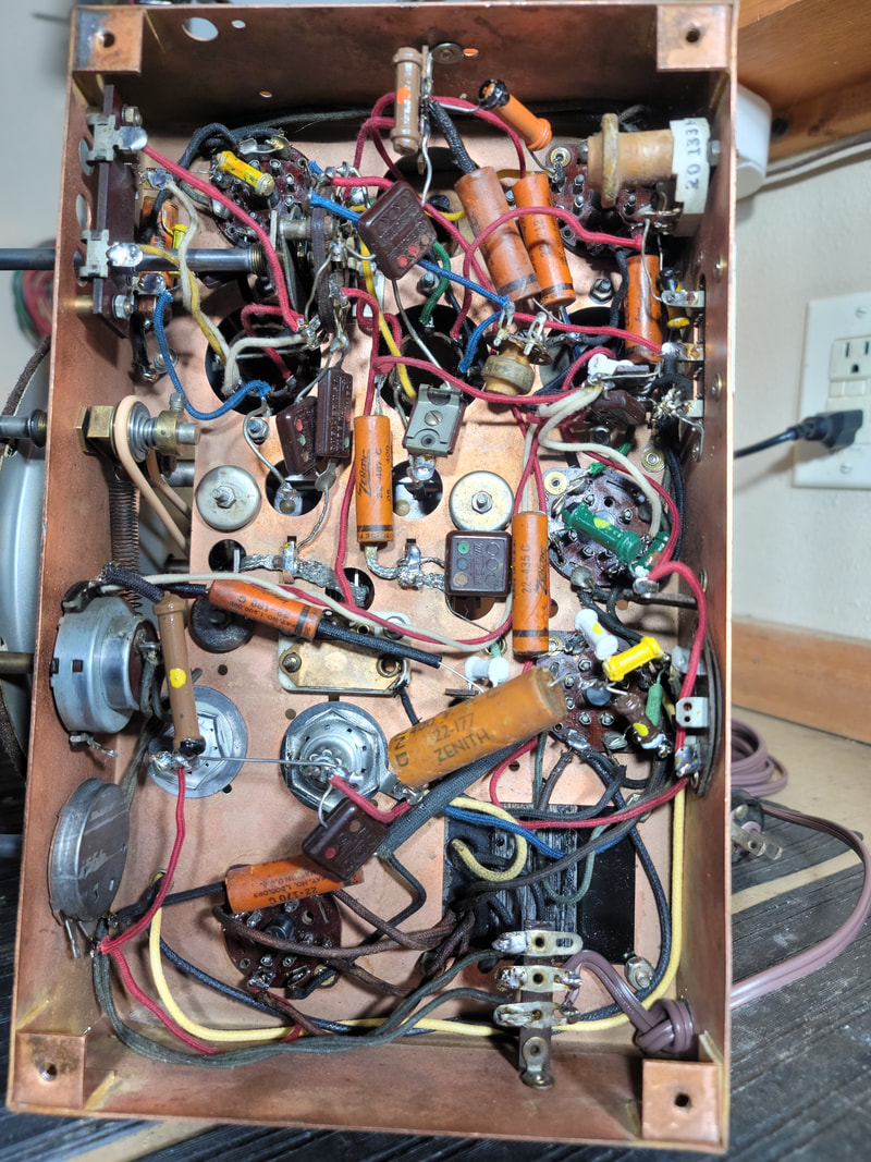
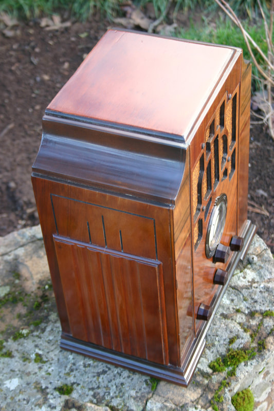
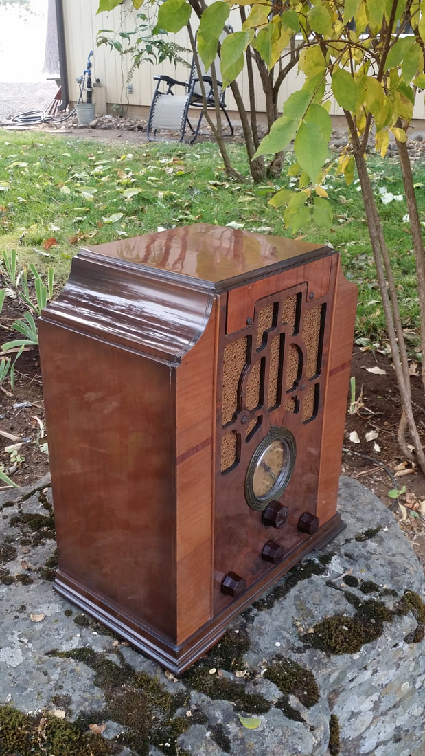
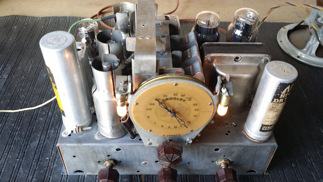
Same as it ever was.
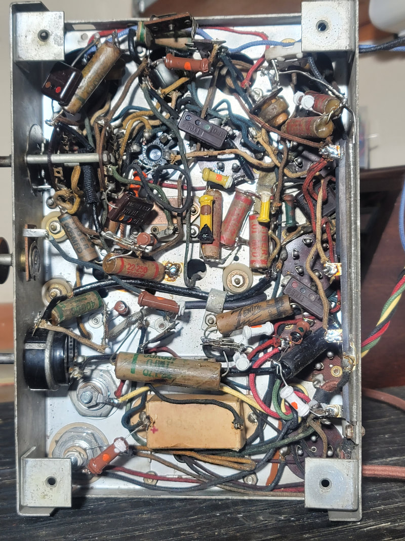
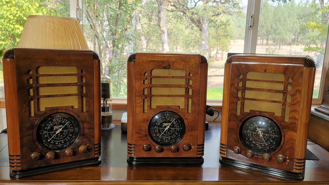
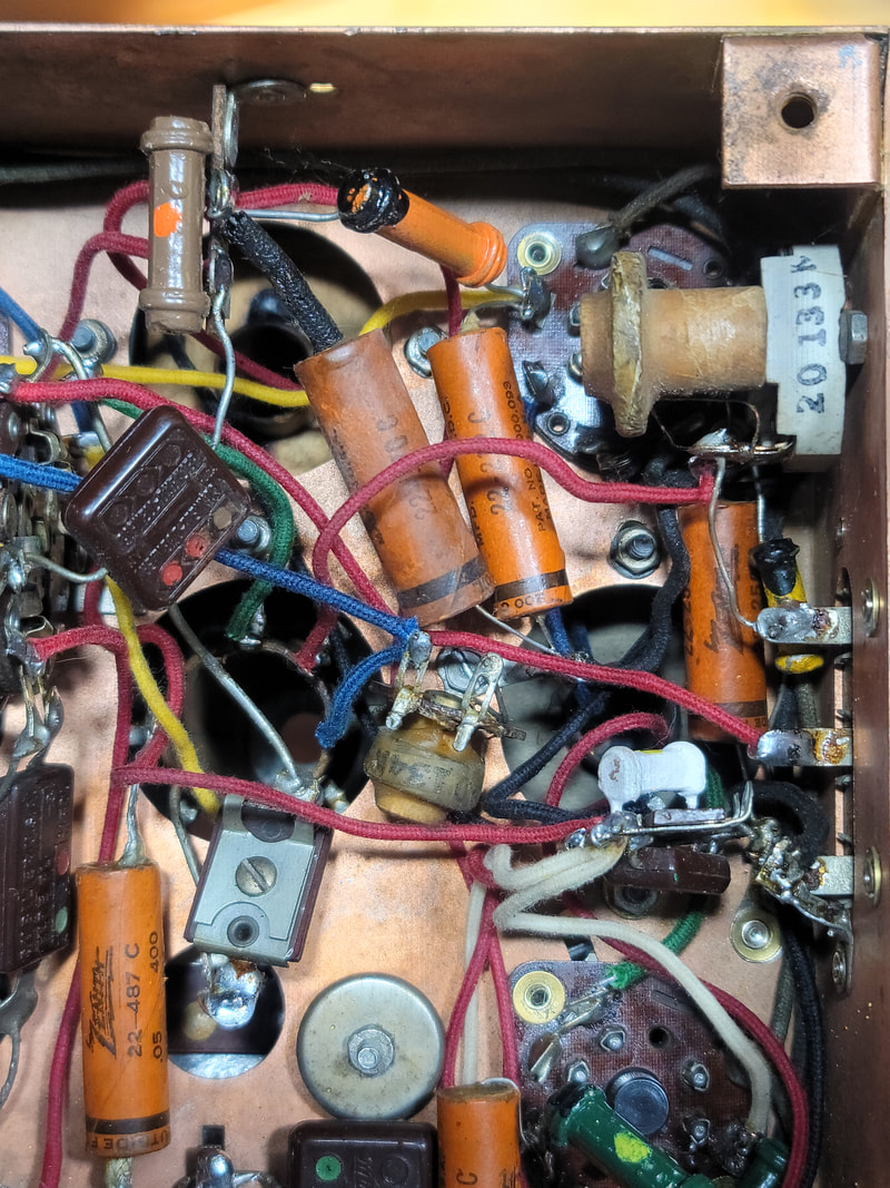
Finished. Yeah, that Solar cap was not original.
Finished. Yeah, that Solar cap was not original.
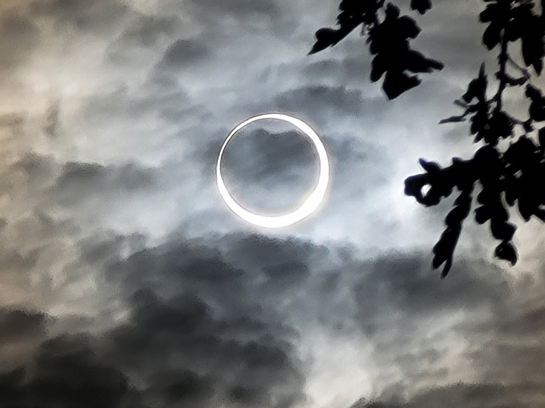
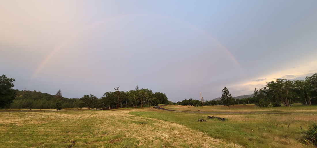
"I'm not missin' a thing, Watchin' the full moon crossing the range", annular eclipse 2023, back 40.
Ridin' The Storm Out
Ridin' The Storm Out
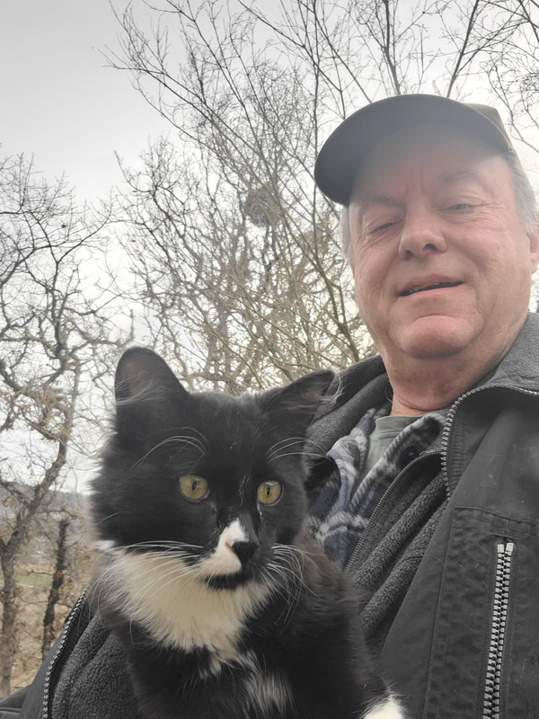
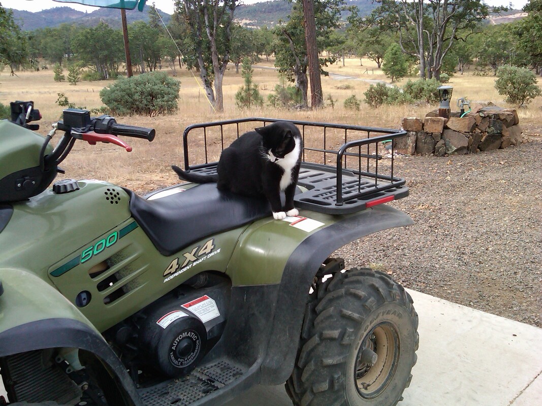
I had to teach my new assistant, Teddy Bear, to ride an ATV.

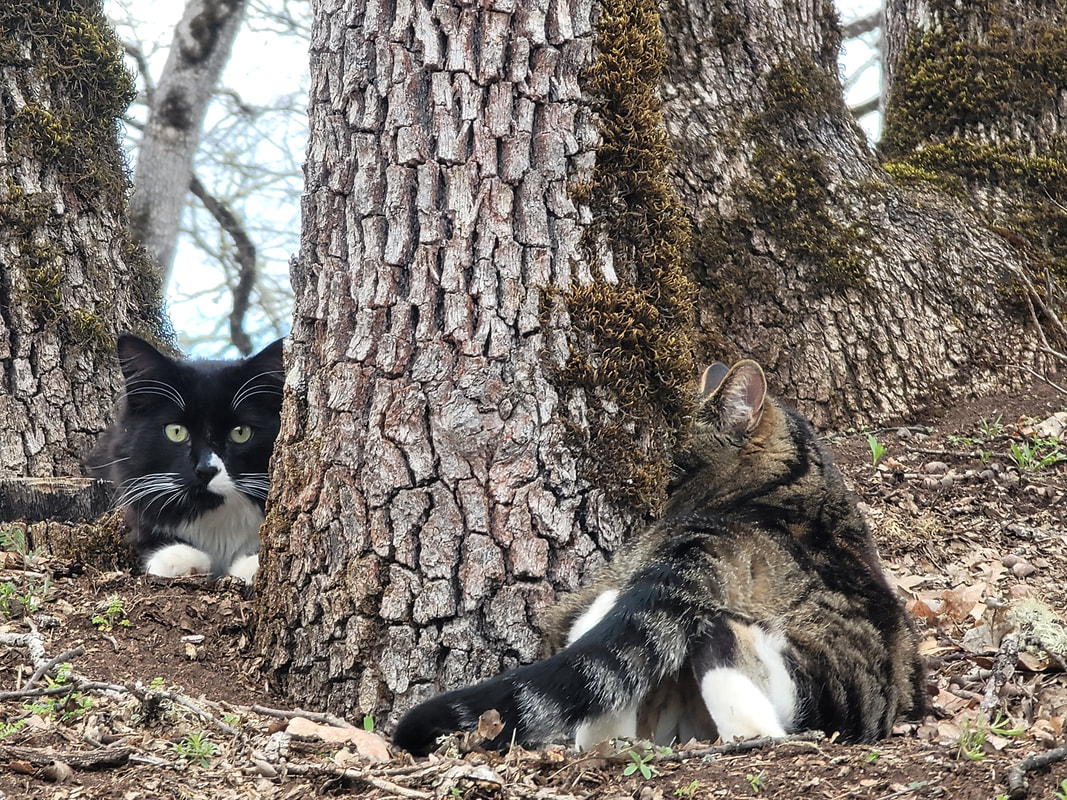
Chasing our tails.
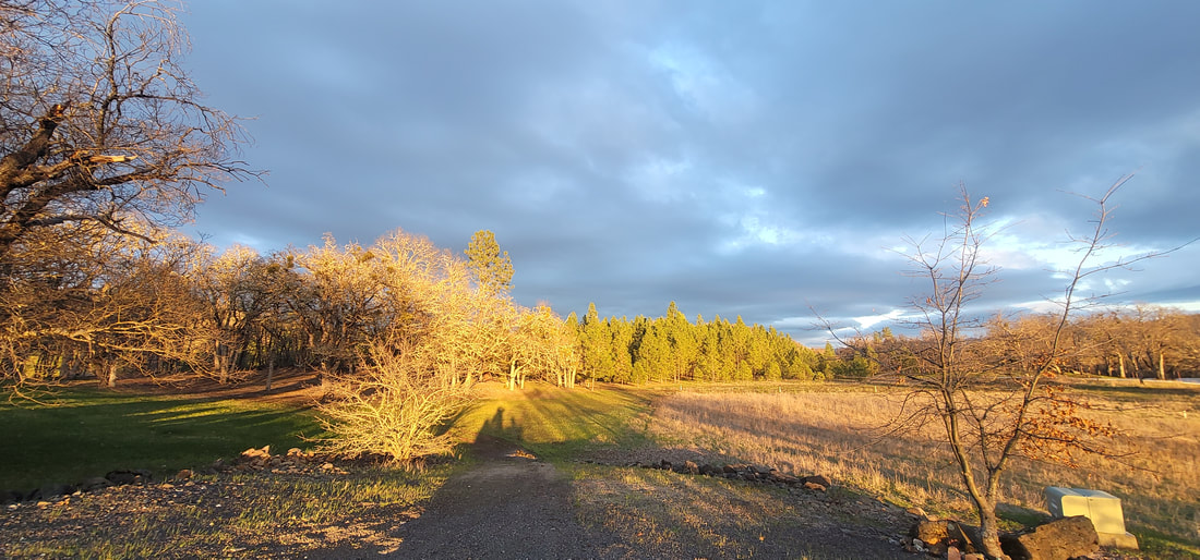
Long shadows at the end of another day.


 RSS Feed