If you can tolerate shopping for tubes on E-Pay you will often encounter the claim that an audio output tube is "tested" or that a pair is "matched", OR that a pair is "NOS", tested and matched. So what does this mean and why is it important?
Well - - "matched" can and often is used to describe tubes as appearing the same, same manufacture, maybe the same date code. Sometimes "NIB" (new in box) is claimed because the tube is in a box with the manufacture matching the label on the tube. These claims are often made without "testing" at all. Often an inexperienced seller will use what he has seen as KEY WORDS in ads placed by experienced sellers. These sellers often don't know if the tube is good or not.
Some sellers are actually trying to be accurate, which is a good thing considering the consequences of making false claims - the loss of a sale + round trip shipping. The problem lies in both understanding and capability of the person making the claim.
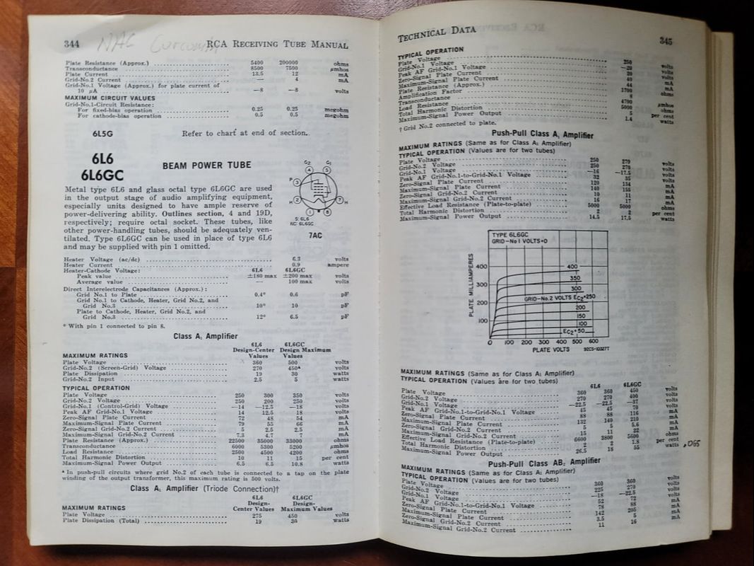
First let's consider new tubes being sold by a real manufacture. I certainly think that claims made by RCA, GE, Mullard and other traditional manufactures of a bygone time were mostly legitimate and accurate. Todays manufactures should also be able to make legitimate claims. Retailers may muddy this picture, but for the purposes of this article, I will exclude claims made by the actual tube manufacture. What's more, the expected test values are often those stated in manufacturer's spec. sheets. Here we will often refer to the specifications (specs) listed in the RCA tube manuals.
N.I.B. - New In Box, never used beyond testing.
Matched Set - A pair of tubes of the same manufacture, similar date of manufacture, which perform nearly equally in all respects throughout their operating range. - for all practical purposes, identical.
N.O.S. - New Old Stock, same as N.I.B. only the box may be missing.
Tested - Covers all extremes from "testing" the filament with an ohm meter to testing with a high-end tube tester.
A matched set of tubes makes for an easier installation especially in an amp that only has one bias pot per channel.
There are many more terms that refer to condition in some way. Many of them don't make much difference to the average user.
Simply stated - the more testing you can do prior to placing a tube in service the less likely you are to experience a bad/smoky outcome.
Even the simplest tube testers have a filament check function or this can be done with a V.O.M. (volt ohm meter). Yet, even here frustration can mount do to a high impedance short that can't even be seen until the tube is hot. I have swapped out so many 227 tubes or even 12AX7s because of a filament cathode leak which produces a "leaves rustling" sound in the output. So even this simplest of tests is not to be taken lightly.
But there is so much more. The issue above is one found in both large and small signal tubes. What else should I consider while testing a tube? Just what can a tube tester tell me? Here is list of tests and terms associated with testing and using vacuum tubes.
Shorts - Most common and probably most important. Results range from low resistance (seen on your V.O.M.) to high impedance which requires accurate calibration even on your high-end tester. Remember, this test not only covers a direct short as seen on your VOM but high impedance shorts like the noisy heater/cathode short that could measure in the tens or even hundreds of thousands of ohms. Tests should be done with the filament lit at normal operating temperature.
Filament/heater voltage - An AC or DC voltage applied to the tubes filament. Needs to be an ACCURATE setting for ALL tubes listed in the tester's charts. Assuming that the builders took filament voltage sag into consideration is a fools errand. If the tube is designed to operate at 6.3 volts anything outside of the normal range (slightly more or less than 6.3V) Will lead to a poor prediction of actual performance. I once heard "I wish that I had known that prior to throwing out a lot of low-testing 245 tubes."
This is probably the most unreliable function of MOST tube testers. It will be of particular concern when testing power tubes with low voltage filaments like the UX-245 (early 45).
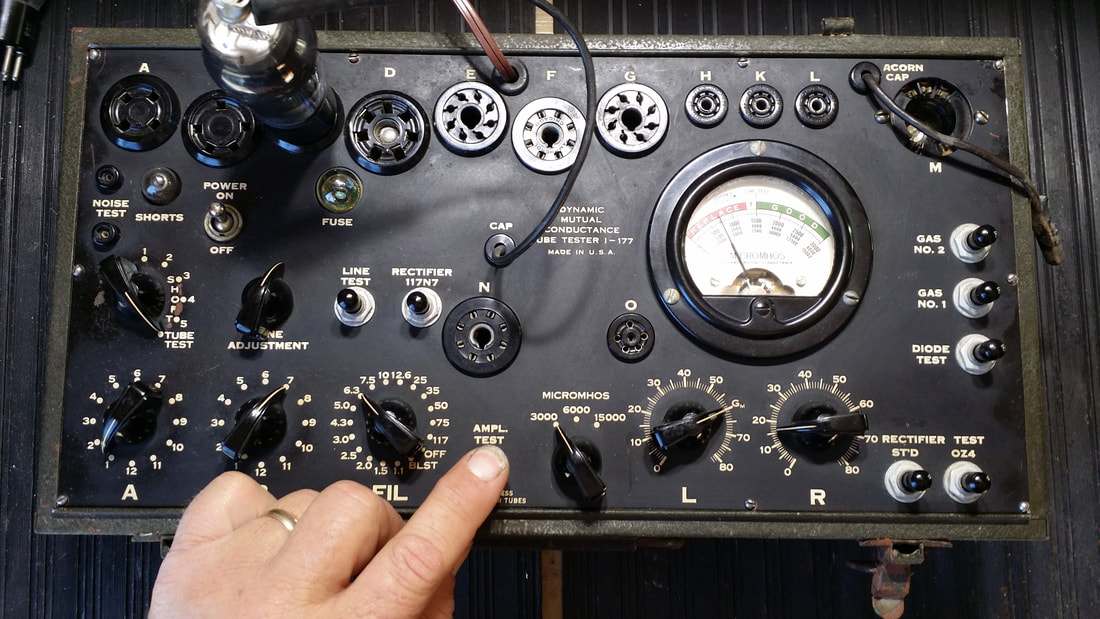
Most testers have a "line voltage adjustment" beyond the rotary switch that indicates which filament voltage tap you are using. So this addresses the problem - right? Yes, up until the time that you push the "test" button. Even a small signal tube with a 2.5V filament is going to draw considerably less B+ current than the UX-245. So when you set the filament at 2.5V, then use the line setting to adjust the meter to the "set" point the difference in B+ current is going to cause the filament voltage to sag since most testers use the same transformer to generate all test voltages. For the test to be accurate a tester would need to realign the set point while the test is being performed. Few testers will allow this, having only one meter, you cant push "test" and look at the filament set-point at the same time. Beyond that, most testers only have limited calibration adjustment for the filament transformer. Most techs try to get the filament voltage right in the 6.3 to 12.6V range, where most tubes operate. This usually leaves the ends of the range - below 5V and above 12.6 - to settle where they will. Some testers have a filament transformer separate from the high voltage transformer to reduce sag in the filament supply caused by a load increase on the B+ while testing.
Hint: While testing a tube in one socket, use another socket to monitor the filament voltage while the test is performed.
Example: While testing a UX-245 in the 4-pin socket (UX), use your VOM to check the filament voltage on the 5-pin socket. A tube with the Hickok "J and R" settings will work but a tube like the 12AX7 , "E and V" settings will not. But you can modify this to work in most cases.
B+ or Plate Voltage - This is the high voltage applied to the plate during a test. Generally the B- voltage (or close to it) will be on the cathode. The screen voltage is often derived from the B+ source. It is DC. It needs to be close to the plate voltage seen in actual operation in a device. It is also subject to sag.
B+ in most tube testers is limited to around 100V. With many small signal tubes like the 12AX7 this is adequate to simulate conditions in a device. For a tube like the 6L6GC this is far below normal operating conditions which can approach 500V.
Screen Grid (G2) - Usually derived from the B+. A positive voltage that is often about 80% of the plate voltage. Screen voltage in a power pentode is applied to the middle of 3 grids. It's value can influence the output of the tube greatly. Also poorly addressed in most tube testers due to the low B+ available.
Control Grid (G1) - The signal voltage is applied to the grid closest to the cathode. This is the signal used to drive the tube. Most tube testers used an AC signal. Early testers like the I-177 injecting 1/2 V which can overdrive some small signal tubes. Bias is the - (negative) DC voltage applied to this grid to control the tube and prevent excessive current flow. With 450V applied to the plate of a 6L6GC, the negative bias voltage is around -37V. A tube tester capable of testing a tube to its max values must also generate this voltage. Most tube testers can't but don't need to because of the low B+ they use.
Suppressor Grid (G3) - Usually at or near the cathode voltage. Close to 0V (B-). Not usually accessible or adjustable in tube testers. It helps to keep stray electrons from hitting and changing the operation of the other electrodes.
The old adage says that if your tube tester indicates that a tube is bad it probably is. If your tube tester indicates that a tube is good, it might be.
Other than detecting shorts, what can a tube tester tell us?
An Emissions Tester will will display a value on it's meter that is often a number between 0 and 100. I am resisting calling this a percentage, but some do. Generally the scale is red-fail, green-pass and yellow-?. The yellow area is usually centered around 50 or 60.
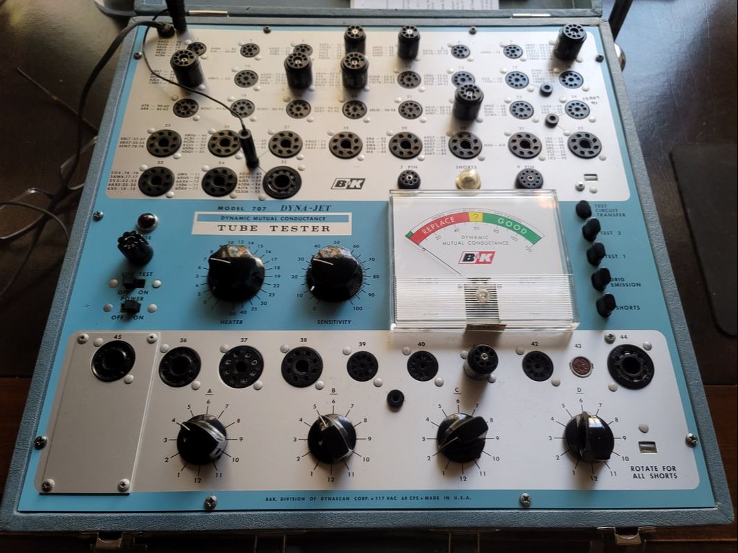
Emissions testers are generally OK for small signal tubes, pass/fail. They can fall short when it comes to power output tube testing. I'll give you an example: One of the OP tubes I often use is the 7868. It is closely related to the 6L6 and really close to the 7591 with a different base (novar). My Hickok testers all lack a novar socket. The only tester I had that could test the 7868 was a Dyna-Jet 707. Though it is a mutual conductance tester, there are a few types that it will only test for emissions. The 7868 is one of them.
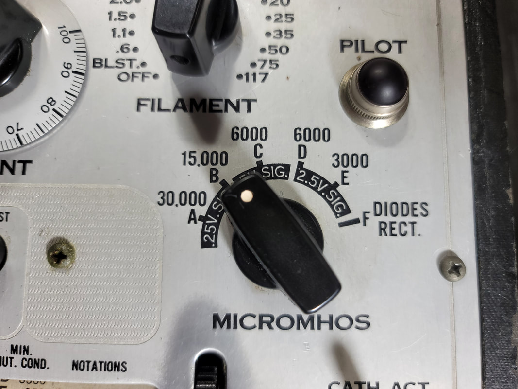
Mutual Conductance - Measured in mhos or micromhos this is the preferred measurement for tube users. Mhos is the opposite of ohms and ohm spelled backward. The process was made popular on Hickok designed testers though some Hickok designed testers were built by other companies (contract TV7s). Others also designed circuits to achieve a similar end. Some testers, like the TV7 used the Hickok circuit but displayed the readings on a numeric scale rather than mhos. Also, to add confusion, some test charts specify a reading that is what they thought a new tube should read, so you had to apply your own failure calculation - now is that 50% or 60%. Some gave you a minimum value below which a tube was considered "bad". The expected mhos reading can vary from one tester to another even in the same brand. That could be expected due to the difference in signal level and plate voltage applied in the test. - - - Confused? You'll get used to it. I recommend further reading for sure.
Following the shorts test, all of the 7868 tubes that I tested on the 707 would pass at around 85. It did not matter whether the tube was new, used, or very used. This really points to the shortcomings of this type tester. I had one very used tube that read around 80. The fact that all of the others were slightly higher made me uneasy about using this tube - but it still passed - for what that is worth. Keep this tube in mind, I'll get back to it later.
The 707 has a very useful feature not found on many tube testers, a Grid Emissions display function.
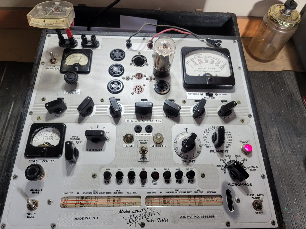
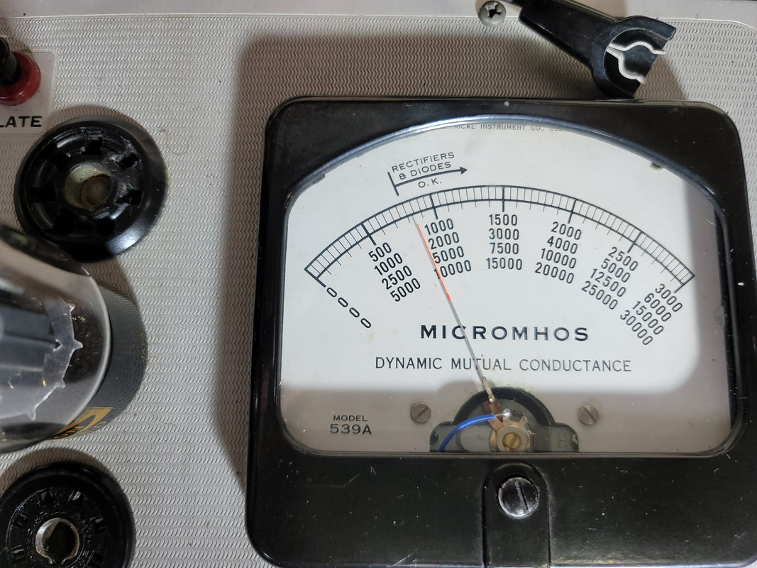
There were a few lab-grade testers but they were quite limited in availability and had high prices THEN. Now they are rare and WAY beyond most peoples budget. Hickok introduced the Model 539 in the middle/late 1950s. It was still expensive and probably beyond the average amateur tech in complexity of operation. The 539C was the latest model. It is a upgrade to earlier models in many respects.
In modern times several testers were developed to accommodate the need for testing power tubes. The Amplitrex is one that is sometimes mentioned in references to matched and tested tubes. It appears to still be available "new manufactured in small quantities". Price is not listed by the manufacture but my research found prices in the thousands of $. I have never tested one of these but they seem to be able to overcome some of the earlier testers shortcomings. Having not used it, I can't offer a review, though there are reviews on-line. Here is the company's site: https://amplitrex.com/
B+ supply could provide about 180V to the plate (closer to 200V on the B,C models)
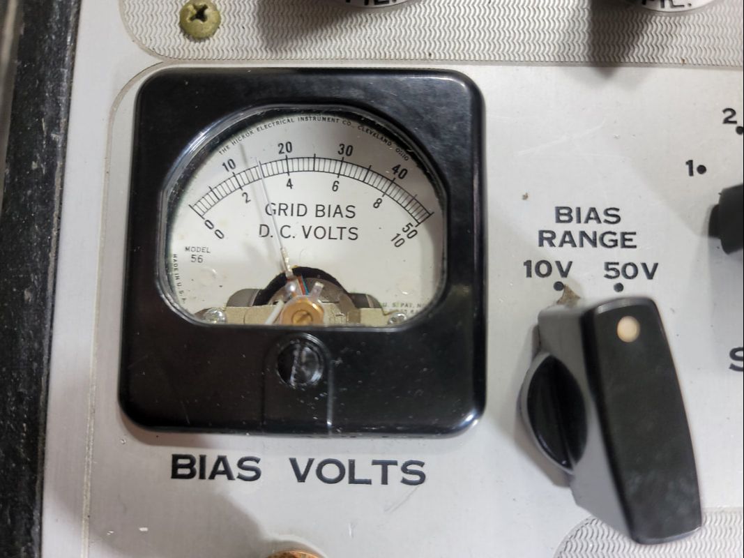
Negative bias could be set by the user and it is displayed in volts on 2 scales up to about -45V (actual).
Signal voltage can be 2.5V or .5V (AC)
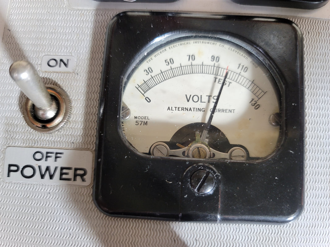
Line voltage is displayed and adjustable during a test (red "set" line = 100V). "Test" button can lock.
Tube performance in mhos on 5 scales
Output for plate current meter/shunt - meter optional
Output for grid current meter/shunt - meter optional
Separate high voltage and filament transformers
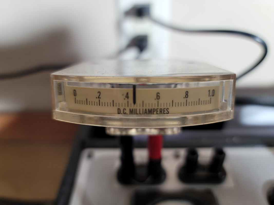
The plate current meter is not incorporated into the 539 but a set of contacts are. If you install a meter (recommended) you will have to change the value of the shunt, which comes with a shorting bar (remove). I used about an inch of nichrome wire as I recall about 29 ohms/ft. The meter is labeled in fractions of a milliamp but with the right shunt I made it read in mA x 10 without the decimal. Fuzzy, in the lower right is the break-out for grid current. I need to get another meter in there. IMHO this mA measurement is at least as important as the measurement of mhos because this is what you need to set up your amp. Tubes should be matched to output in mA at rated power with negative bias the same or very close.
Build your own tube tester. The best vintage testers, like the Hickok 539, A,B,C and the more modern testers like the Amplitrex are EXPENSIVE(! ) And difficult to maintain and calibrate. Some don't even have a clearly understandable calibration method (like my 539A). Some have limited testing charts (like my 539A). You can avoid all of this building your own.
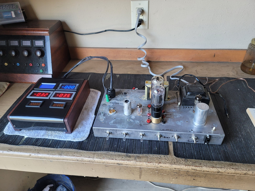
Cost to build my tester was a little more than $100. You may already own an old PA amp which is not really suited to use in your hi-fi setup. (Audio quality aside, They are kind of ugly especially when you stack up 2 of them). The meters I used are cheap on Pay-Bay (around $10ea for Chinese made). All of the rest of the parts came out of the junk drawer (inventory). It came with 2 VERY used 7868s. I have a push-pull 7189 amp which I intend to configure for the 6BQ5 family of tubes. My 6BQ5 tester will use the same plug in display.
The adaptors, 7868 to 7591 and 7591 to 6l6G,GB,GC are also available on P-Bay, or build your own.
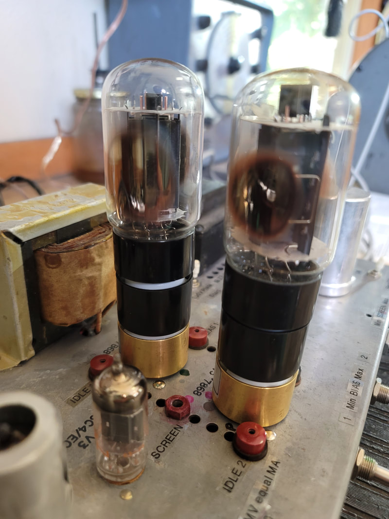
Note the brown edges on the getter. This indicates a used tube. My theory is that, temperatures of the electrodes and electron bombardment vaporize coatings and possibly metals. These can precipitate on cooler surfaces like the mica insulators unless absorbed by the getter. Note also the difference from a tube that has "gone to air" (loss of vacuum) in which the getter turns white. Red plating can make this much worse than "normal" use. Deposits on the micas of my 7868 tube probably lead to it's runaway condition.
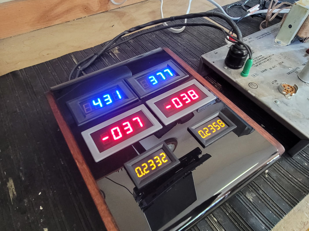
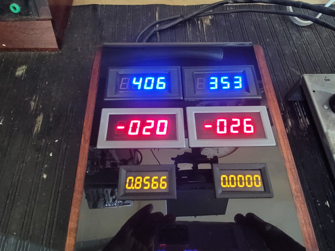
B+ Plate Voltage Screen Voltage
Bias (1) Bias (2)
Milliamps(1) Milliamps(2) Both must be /10 to account for the 10ohm cathode resistor, .2332 = .02332 amps = 23.3mA Display is mV which converts to mA.
Finding meters that display down to 3 digits before the decimal is necessary for the output current and there seems to be limited choices at this time. (accounting for the smaller size meters)
You will need to add:
A filtered supply ~ 5 - 12V DC for the meter display. In my case removing the 6EU7 tube from the Bogan saved about as much power as was required. The 6EU7 was the preamp used with a phono. The 6.3V AC filament supply is good for this.
A filtered negative bias supply. Use a full wave or bridge rectifier and maybe a voltage doubler on the existing bias supply. It needs to be adjustable from ~3V to -45 or -50V somewhat independent on each side (tube 1 & 2)
Variable control of the screen supply. There is little current needed. 1 control.
I kept my tube rectifier and added a filament on/off switch. This allows the filaments of the tubes being tested to warm prior to turning the rectifier filament on. Watching the display through warm-up allows for a quick shutdown if trouble exists. The tube rectifier protects the power trans better than a solid state rect. But, more plate voltage would be available using sand (solid state).
Tone controls can be replaced with the new controls required for testing. (no need to drill)
I had installed test ports on the Bogan. They are handy but redundant and were used prior to building the meter box.
The Bogan was built to supply 35 watts output from the pair of 7868 tubes. This was really putting the squeeze on them (She won't take much more of this Captain.). The schematic spec. was lower but testing reveled that about 410V on the screen would get you that 35W and that is where it was when found. I would recommend not exceeding the values in the RCA manual. Dropping the screen and raising the negative bias slightly will not make a noticeable change in sound but will save your expensive toobes. With this tester you can listen to the results and make changes accordingly. Don't forget - this is the tester. Anything you decide will have to be applied to the actual amp in which tubes are to be used.
AND - - should I mention that you need to know the values used in the actual device (amp) prior to setting up this tester. It is easier to adapt a 6L6GC amp to this function than a 6L6G amp. Higher B+ will already be available as well as screen and negative bias.
Will your average mutual conductance or emissions tester match tubes used in high level audio outputs? No. This includes the ever popular TV7.
Will your average mutual conductance or emissions tester test tubes for quality/performance in high level, real world applications? No.
Will your average mutual conductance or emissions tester test small signal tubes. Yes
Will a cheap tube tester perform any useful test? Yes, if the shorts tester is working properly.
Can you build a reliable tester? Yes
You can also set up your receiver/amp to test its own tubes using a VOM and a handful of parts but this is risky if you ever encounter a tube with a high impedance short (not found by a shorts tester). A runaway tube can take out an output transformer before you get your meter on the right pins. (don't ignore that hum in the output. One side of the PP outputs may be conducting a lot of DC through the primary winding).
I tested the previously mentioned 7868. Along side of another 7868 it was doing 8mA when the other tube was near full power. I began turning down the - bias (becoming more +), still 8mA. Eventually I hit a bias point that the output began to rise. Without adjusting the bias further it continued to rise - quickly. I did not wait to see how far it would go. And it hit the trash can a bit later. Remember, the DJ 707 said it was OK. I did not have an adaptor to sub it into an octal socket on the Hickok 533, but I suspect, passing the shorts test, a failure would not have been indicated, though I do not know what the GM would have been. The 533 also has a relatively low plate voltage.
There are a lot of testers not covered here. There are a lot of tubes not covered here. I have included a few of the modifications to the Bogan amp I used since the one you use will probably be different. If you have any questions, you can post them below.
I think that this will always be a work in progress.
Russ


 RSS Feed