
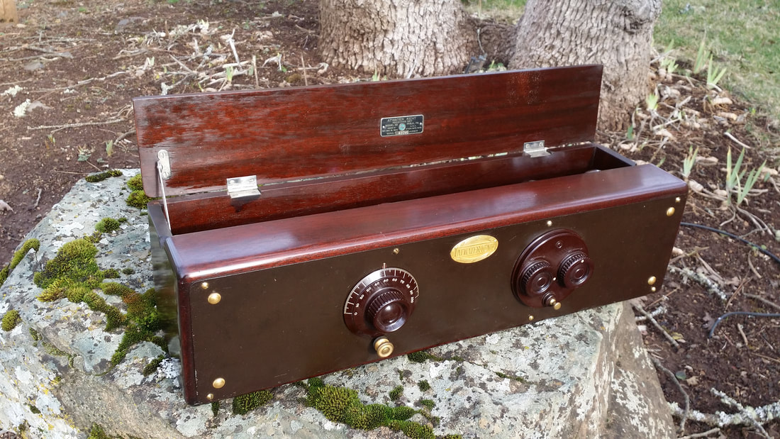
The box said "AL's radio". Inside was a 3-tube Acme radio with other accessories from the early 1920's. It had been preserved so well. It must have been important to Al. Now, nearly 100 years after it was made, his nephew was allowing me to take responsibility for it's future. I will do my best.
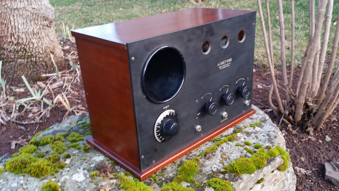
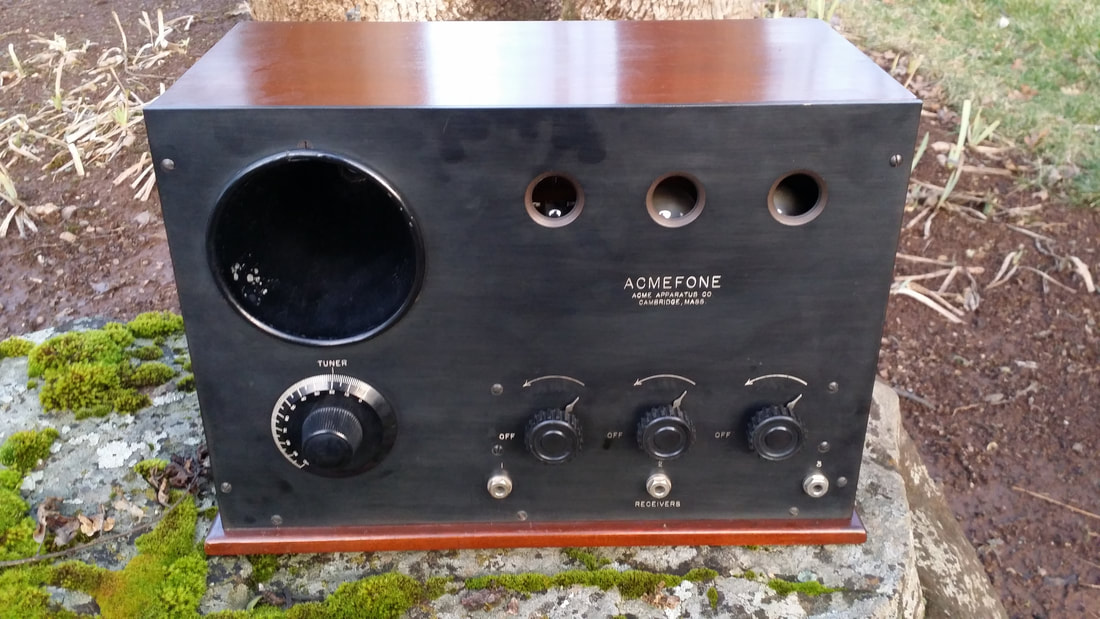
This receiver was manufactured by Acme Apparatus Co., Cambridge MA.
As-found above
This 3 tube receiver is comprised of a UV200 detector and two stages of audio amplification. The audio stages incorporate 4 ohm rheostats controlling the filaments. These low resistance rheostats point to the original use of 1 amp UV 201s in the audio stages that would be consistent with a radio made in 1921 - early 1922. So all three tubes would have been the early brass-based/tipped 1 amp versions.
It is really tough to tell, but the original finish is either so good or possibly has been neatly top-coated at some time. In any case. the very slight cracking of the original shellac is visible if you look VERY closely.
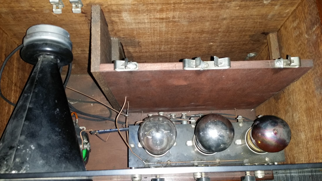
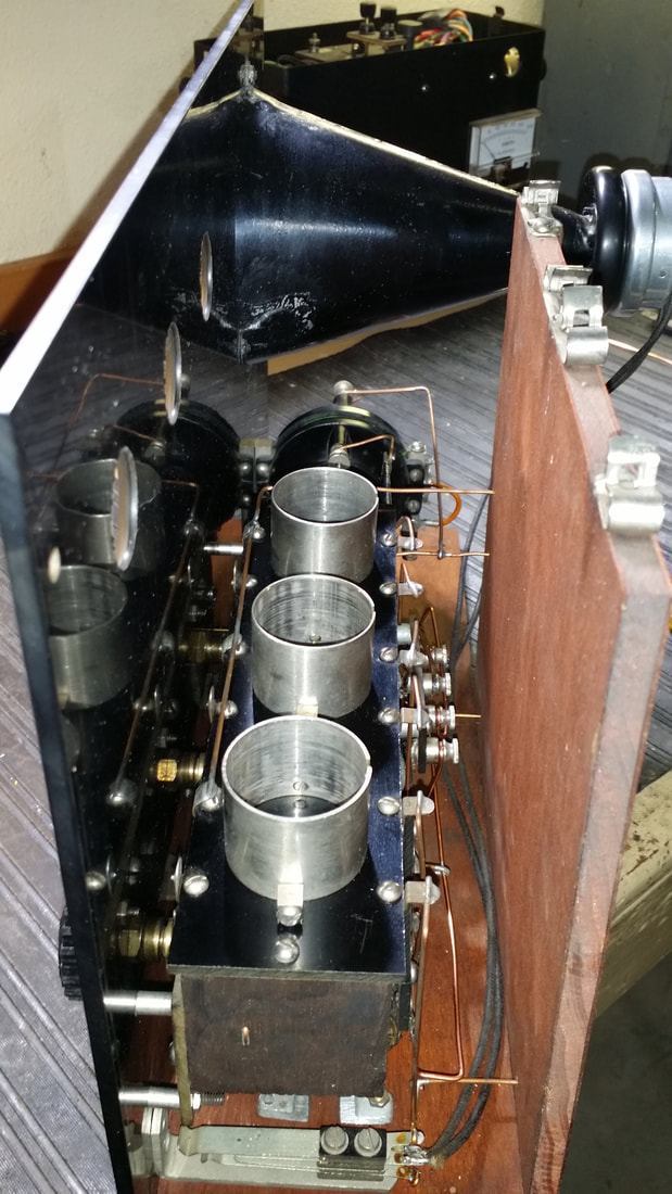
Not only is there a storage space for B batteries, but also an internal horn speaker.
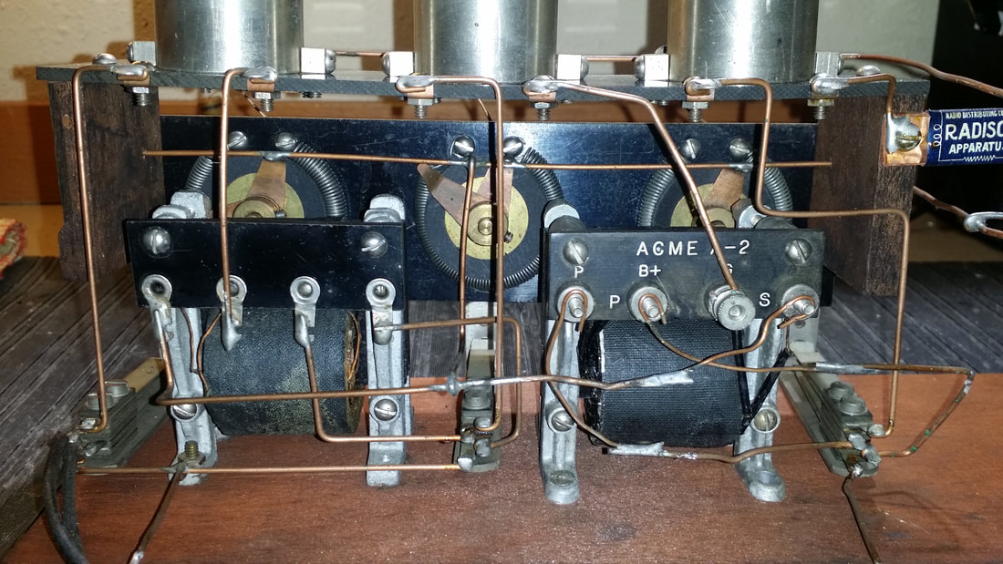
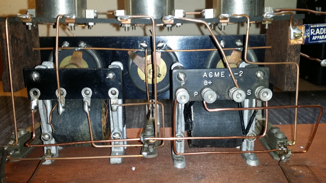
In the picture above you can see the splices that were made when the right Acme interstage transformer was replaced with a slightly later model. The secondary on this trans. was found to be open and was the only repair that needed to be made to make the radio work again.
While there would be some historical perspective maintained by leaving the spliced buss wires, I just could not do that. So the completed repair is pictured below.
While there would be some historical perspective maintained by leaving the spliced buss wires, I just could not do that. So the completed repair is pictured below.
There appear to be other post-production modifications done to this radio besides the audio trans. repair. Most apparent is the piece of plywood added to the front of the battery storage area. This modification appears to be nearly as old as the radio. The construction of the plywood is period correct and it was stained to match the finish. This mod incorporated a change to the method of B battery attachment. This change made changing batteries much easier. It also allows for the use of both B+ and detector (22.5V) connections.
There is some speculation that a variable cap prior to the detector was replaced with a variometer. While this change might have reduced selectivity it probably improved antenna performance. In 1922 the ability to tune to the antenna is more significant than selectivity since all radio stations were on only ONE or two frequencies. The history of frequency assignment is discussed in the article referenced below.
With or without the variometer there is no signal gain prior to the UV 200 detector. So the "range" of this receiver is very limited. The UV 200 was a good choice at the time but the radio has insufficient control to really take advantage of it. The filament control is very rough and, in the best case, some method of of controlling the detector B+ would have been necessary.
It is possible that all of the repairs and modifications to this radio were made at the same time. While all of the work appears to be professionally done it also appears to be well planned and the person performing the repair must have been experienced with these modifications.
In my years as a radio tech I participated in several large manufacture's sponsored recalls with required modifications. After a few dozen repairs a tech would get very good at it. In my opinion, repairs to this unit might have been a part of a rebuild/reissue effort.
I believe that all of the modifications were improvements. Looking at the front panel behind the tuning knob, the panel is neatly and accurately drilled for both a tuning cap (3 holes) and for the variometer (2 holes). All of the holes arel countersunk and clean. This is almost never the case in field modifications.
Consider the possibility that this radio was a warranty repair/return. While very few of these exist there are notes online that seem to indicate that another unit had many similar modifications. A couple of the early UV type tubes have Pacific States Electric tags. This company was a reseller of considerable size. Is it possible that they acquired returned and unsold units and modified them?
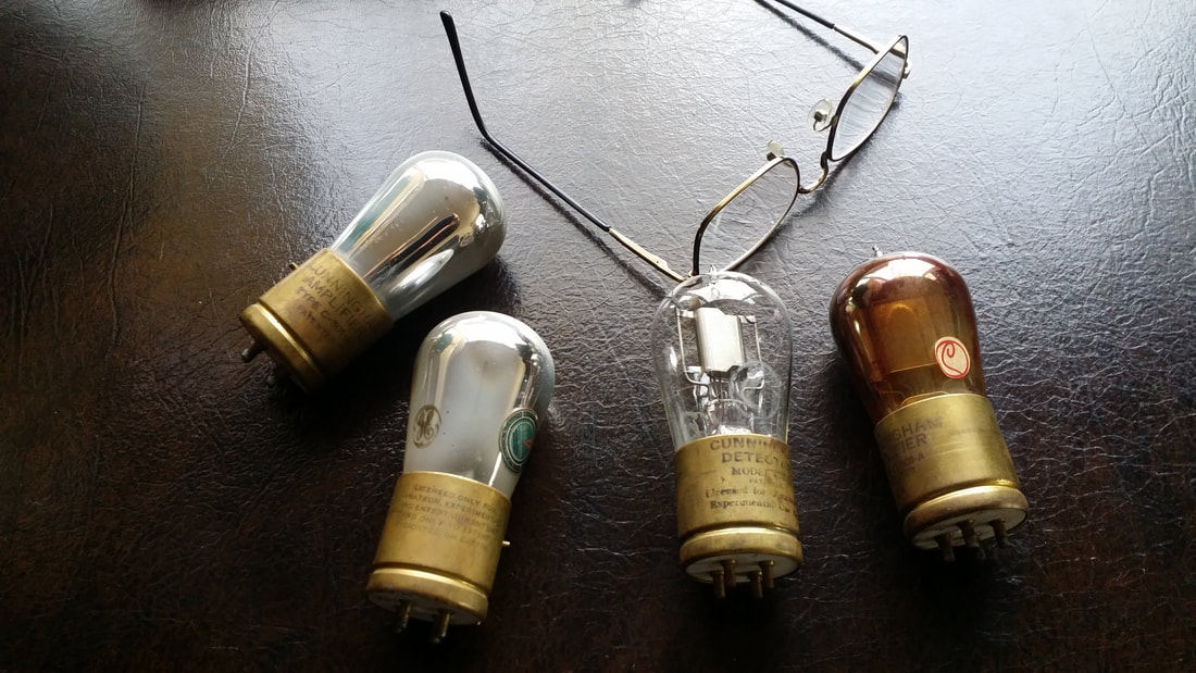
UV 200 (stock) and UV 201A replacement tubes. The early UV 200 is the tube with no getter.
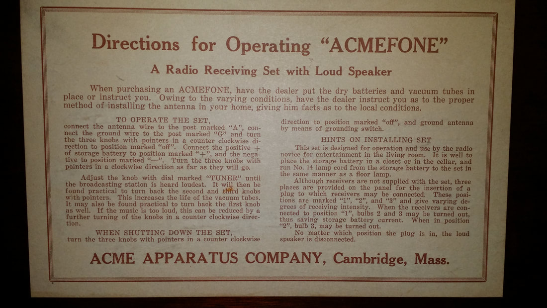
Below is an explanation for the relatively unselective design of the Acmefone. This is an excerpt from a remarkably complete history of broadcasting compiled by my friend Ron Kramer.
The contemporary radio listener probably cannot appreciate conditions of radio service in 1922. Stations broadcast sporadically because there were so many trying to use the same frequencies. In fact, in 1921 and early 1922, only one frequency was authorized - 833 KHz (although until about 1930 frequencies were commonly expressed in the actual length of the wave and referred to as wave lengths, in this case 360 meters). All stations broadcast at the same spot on the dial which obviously meant they could not all broadcast at once without interference. In a kind of gentlemens' agreement, they shared the frequency. By late 1922 the growth in the number of stations forced the U.S. Department of Commerce, which was then responsible for radio regulation, to authorize a second frequency of 750 KHz (or 400 meters). Smaller stations, which included those which used phonograph recordings, were required to stay on the old 833 KHz frequency but the first class stations could use 750 KHz, which was a less congested neighborhood.
The complete document was part of an effort to build The Western States Museum of Broadcasting, a project that is on hold, for the moment. It is available as an archived document here:
https://web.archive.org/web/20150404142651/http://www.wsmb.org/Page.asp?NavID=19
If you get a chance , I would recommend reading the entire history. While much of it is specific to S. Oregon, I am sure that the story was replicated in many large and small communities in the early 1920's
Thanks again to Ron for making this piece of radio history available to us.
Below are video demonstrations of the Acmefone in operation. There is a considerable improvement in audio using the RCA cone speaker over the onboard horn. Also, the horn driver might have been replace along with the other repairs.
Multiple stations are heard at any setting but tuning the variometer does improve the signal of the local boomer - Spanish language station.
AND for this demonstration I cheated - a little. I substituted my UX 201A substitute tube for the UV 200 detector which allowed for speaker-level audio rather than headphone-level audio. SEE the blog post on tube substitution below.
The Acmefone is now available for viewing by appointment at Russ' Old Radio shop/museum.

 RSS Feed