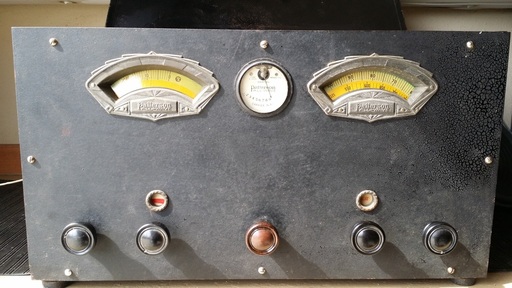
But this time I had to bend over and carry it out to the truck at arms length. Did I mention that it was dirty? I don't want to be more descriptive, but, it just wasn't something you wanted to touch. OH(!) what we will do for a historic radio. With all of the dials caked with ?? and the meter upside-down, the metal box was just not the kind of radio that I am usually attracted to. But this time it either had to be saved or risk going to the dump. Oakley is well into his 90s and sharp as a pin but housework was getting to be too much for him. So he was moving.
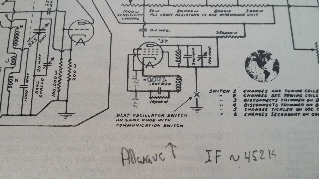
One of the differences between this radio and the later PR-10 seems to be the IF frequency. The PR-10 has an IF running at 432.5 kHz but this radio seems to want to be tuned around 450 kHz. Though I could find no specific documentation, the IF was running near 450 kHz when I finished the restoration. I tried to push it down to 432.5 and while it would go there it lost a lot of gain and the BFO just would not work. So simple using performance and what I expected from the range in the IF transformer tuning caps, I reset it to about 452 kHz. I had one IF transformer that was intermittently noisy from a bad ground but I found that and fixed it.
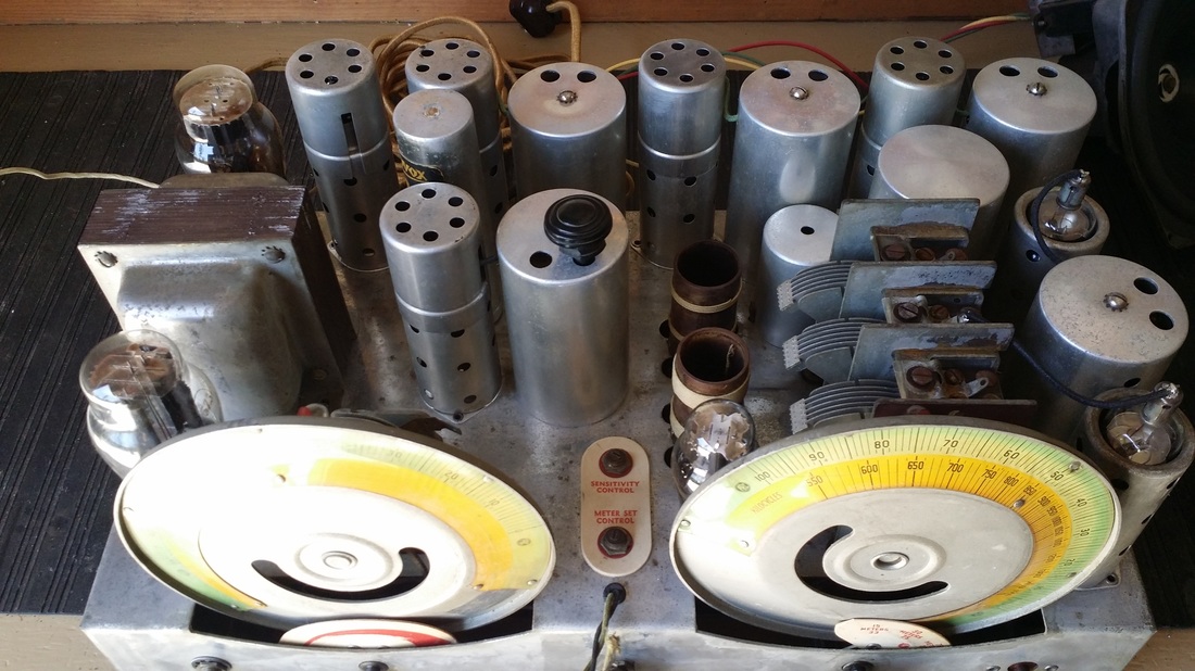
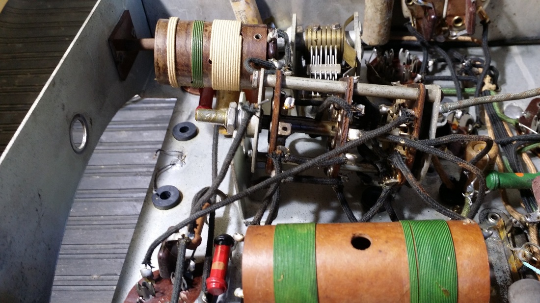
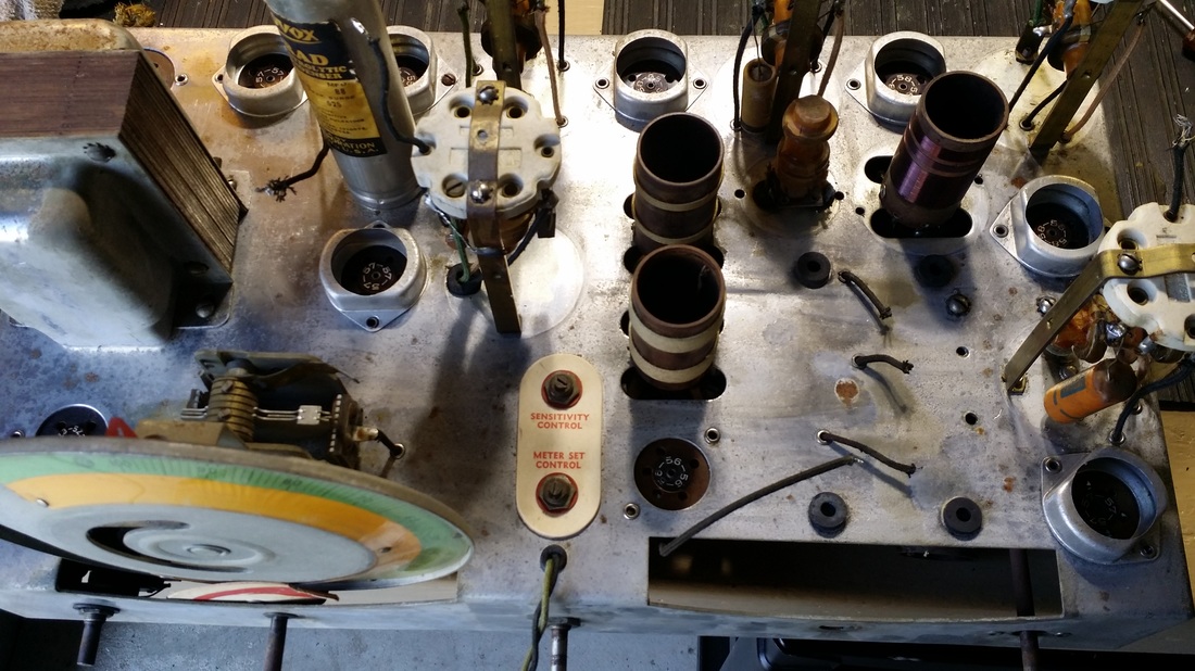
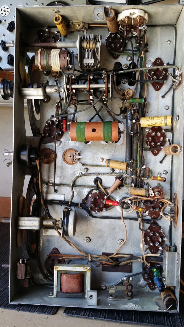
The chassis was in good shape.
The rubber friction drive components for the tuning mechanisms were also replaced at the stage.
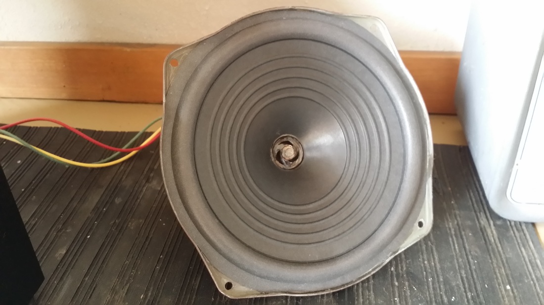
So I had this Philco 20 speaker laying around. I stuck a new cone in it. The specs on the FC and output transformer were close enough. And it works just fine.
Below is a video of the All-Wave in operation.
A few notes:
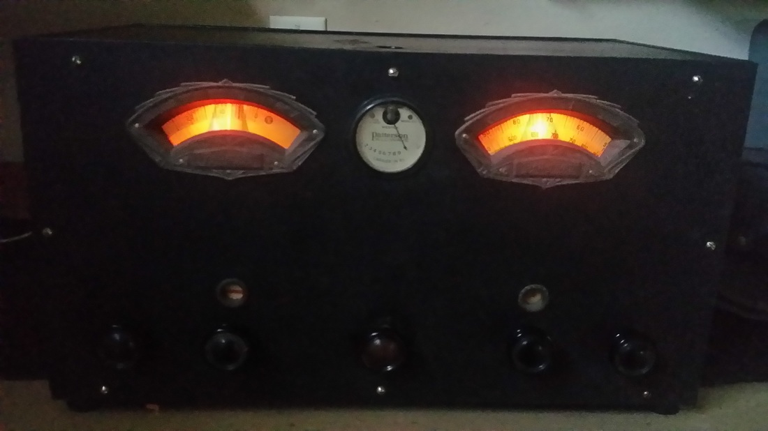
It is frequently necessary to "0" the S meter (in this case "R" meter)
The BFO needs to be retuned over time and band changes. You can 0-beat it or just adjust the output for the highest gain on the S meter.
The BFO was intended to receive CW transmissions at the time the radio was built. In the video I use it to generate a carrier needed to demodulate single sideband (SSB). It is not ideally suited for this purpose. The demonstration of the CW reception demonstrates its original purpose. In several of these clips I had not yet found the poor ground in an IF can. So later the noise floor was dropped considerably.
http://www.radioblvd.com/Patterson%20PR-10.htm
Most of the "upgrades" mentioned at the site above were incorporated into this radio. There is a significant difference in the construction of the BFO circuit. I hope that you can make out my notes in the Riders Manual below. Yes, the grid (top cap) is grounded.


 RSS Feed