 The AC-61 or AC61 is working. A power transformer from a Philco 90 was used to replace the missing original. The 90's transformer had all of the original leads replaced prior to installation as well as combining the two 2.5 volt, center tapped, filament windings into one. 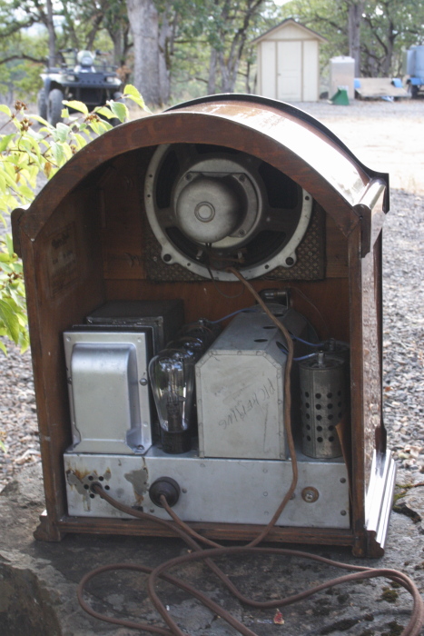 The interstage transformer had failed and someone had attempted a cap coupled bypass off of the 224 detector. I doubt that this worked very well. This transformer must provide grid voltage for the push-pull 245s. The model AC70 added a 227 tube to overcome the challenge of using a 224 as both a detector and a first audio stage. Another very interesting design element is the use of the 2.5V filament center tap to provide voltage for the speaker field coil. The plate current of the two 245s provides 48V to the field coil which is 800 ohms. Auto biasing is still accomplished, but there is a .3uf cap added as a bypass around the field coil to ground. I can't recall ever having seen this before. 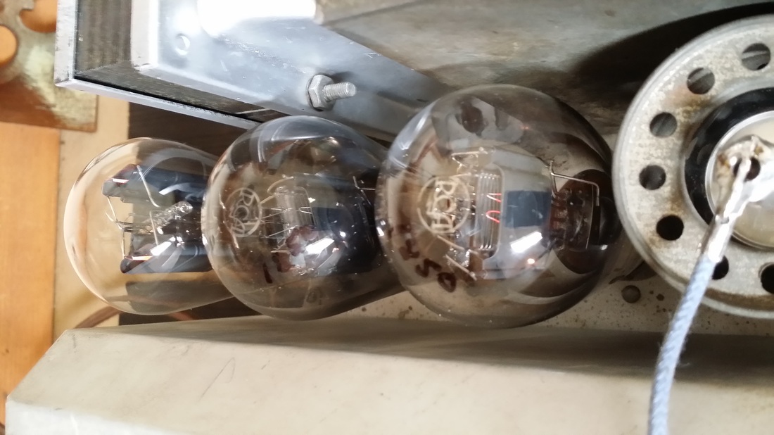 Having aligned the radio which is a TRF, I tuned several of our local stations all of which have about the same program material - conservative talk radio. Then it dawned on me! This radio is proof of the claim that the news media has a "liberal" bias. (SEE earlier posting). This radio definitely is "left of center". 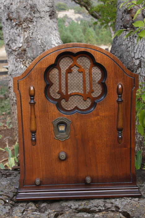 I wanted to bring balance to the radio by leaving it on various conservative programs for several days, all in an attempt to move it to the right, making it more "fair and balanced", but it seemed to have little or no effect- on the radio. (insert smilie HERE) On the other hand I fashioned a tinfoil helmet for myself to keep the government out of my head.
Russ You know, up until April I worked for the phone company, the one with the "V", which is technically correct but only true for about a month. Prior to that the big "V" I worked for was a cellular phone company. Only after spending a Bazillion $ did we become ONE. Anyway., let us go back in time to 1985. I was still working for various MSS and GESS (Motorola and GE radio service shops. There were "mobile" telephones around, we worked on them all the time . They were large heavy beasts that used a centronix cable to link a BIG UGLY handset to an even bigger UGLIER 2-way radio in the trunk. The best of them used a system called IMTS or "Improved Mobile Telephone Service". It was ""improved" from RCC which usually involved an operator dialing calls for you. By the end of this era there were so may users on 5 or 6 usable frequencies, the only phones that could "grab a channel" had to scan for an open frequency by themselves. While everyone else had to wait - more. But, not to be unentertained, they all got to listen to your call - even if they did not want to. Otherwise the manual process had no chance on a busy day. You might as well just drive there and talk to them in person. Not to mention, that if you did get to make a call it was at 50 cents a minuet and a monthly charge of around $40 - even if you could never make a call. So it was no wonder that, at some point, this wonderful radio was headed for the garbage can. 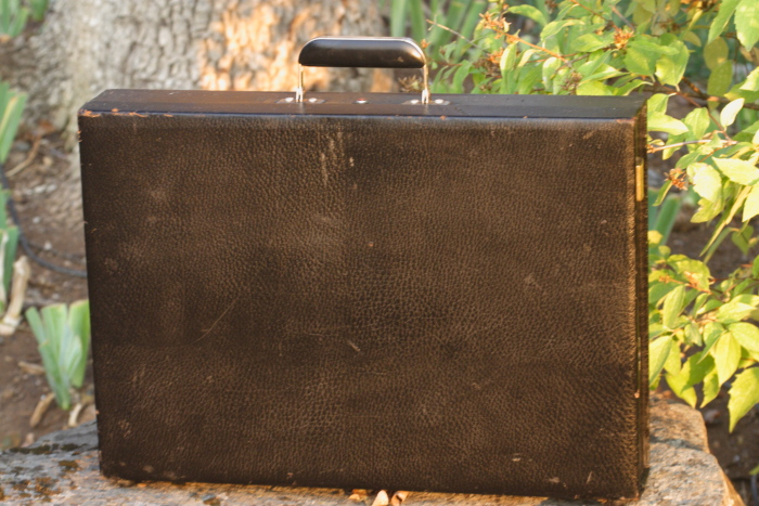 Not quite Maxwell Smart's shoe phone, but I believe that this is, if not the first (or only), one of the first commercially made HAND HELD(?!) IMTS phones. It runs on 12 volts and has (had) a set of rechargeable ni-cad batteries inside, which would have given you a few minutes of talk time. 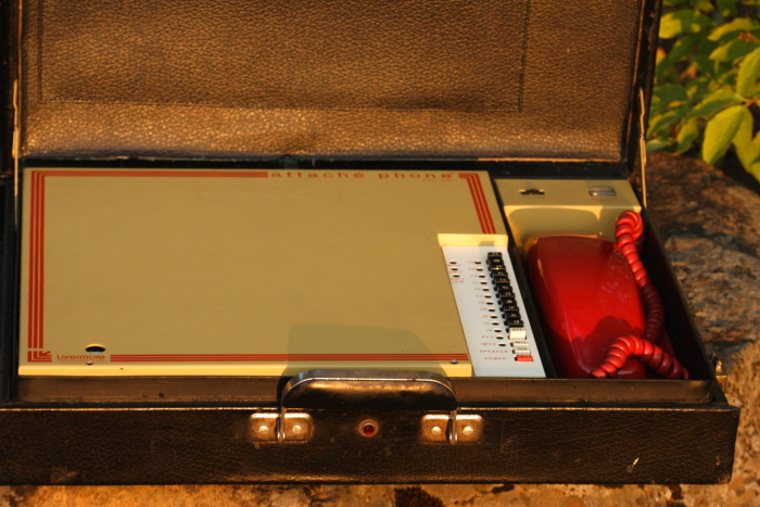 Yes, that is a RED princess phone. 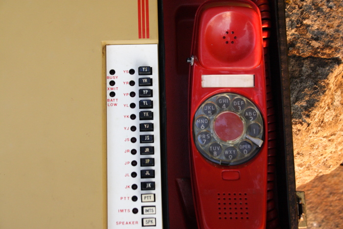 DTMF - yeah, right! not on this baby. Note also the PTT button (Push To Talk) on the upper part of the handset just incase you had to lower yourself to using an old RCC carrier. While in the subject of PTT, I have never figured out why people thought PTT on a cell phone was a great deal. In the day of this phone people could not get rid of that little button fast enough. 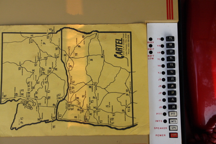 The service providers were a mish mash of large and small telecoms, paging companies and whatnot. It helped to know where you were at and what channels were available. So it came with a map.
So in 1985 and then on, I assisted in the conversion of the nation to AMPS - yes - cell phones (Advanced Mobile Phone Service), from which eventually begot NAMPS, CDMA, PCS, GSM, SMS, 3G, 4G, EVDO, LTE, VoLTE, a lot of other letters and your smart phone. I just found this thing on the shelf where it has resided for about 10 years and thought you might be interested. P.S. The receiver is functional but the PA (power amp) has a bad OP transistor, not that there is anyone to talk to anyway. Russ 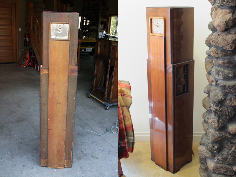 Nothing like listening to a football game on your Westinghouse Columaire, except for that tick - tick - tick. Well actually, I am very happy with that too. We found a suitable second hand and the clock is keeping perfect time. 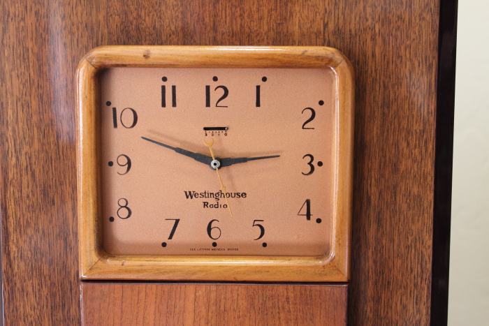 It took a while to put it back together. I know now why that center brace is missing on most of them. It is in the way for just about anything you want to do. Notice that, along with a new back, this one also has a new brace (light colored wood). 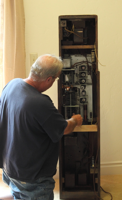 Another hint to the next person that tries to align the motor drive for the remote tuning/on/off/volume - gravity has a lot to do with the way it works. Spring tension must be set with the receiver on its side (as in operation). Note the phonograph (amp) option in the upper left corner. So this R version radio (remote) also has the phono option that could be used for an MP3 device - no I don't intend to. I am not going to wire in the remote box on its 12 conductor cable at this time, but display the remote its self near the radio. The big cable is not that attractive. It originally used a flat cable and one of those grey ribbon cables would work, but, not for now. On the video below, the remote tuning functions are demonstrated by the duplicate pushbuttons on the control panel. Note the movement of the tuning knob and the lack of a on/off/volume knob. The small knob is local/distance and the phono/radio switch is part of the assembly with the switch on the back. 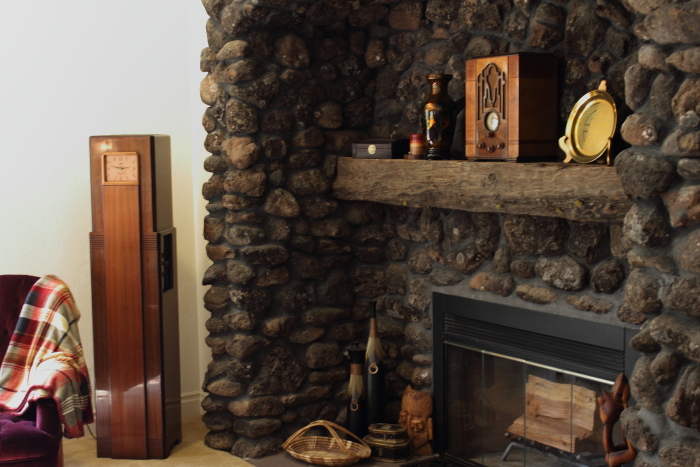 Alas - One more radio in the living room. One more note on the Westinghouse WR-8 and WR-8-R, all of the veneer is mahogany. Only the dyes used are different. Almost no toner was used on this cabinet. There were countless areas that needed veneer grafts. It seems that the decorative areas in the corners are almost always damaged.
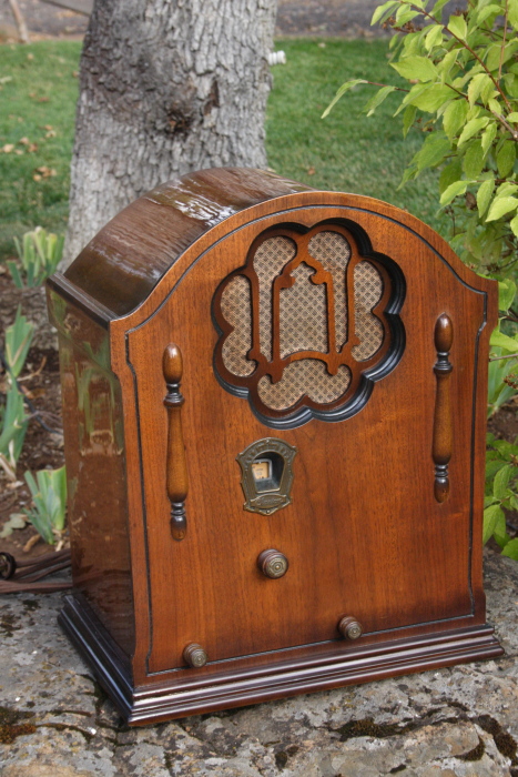
It should also be noted that this radio has a very high center of gravity and a small base. Care must be taken not to knock it over especially if small children or guys with footballs/etc. are in the room. I am sure that the engineer that designed both of these early 30s radios thought that function was preferred over form. And, after a while, the off-center dial and knobs don't look as odd as they do upon first impression. Clarion AC61 and Clarion AC70 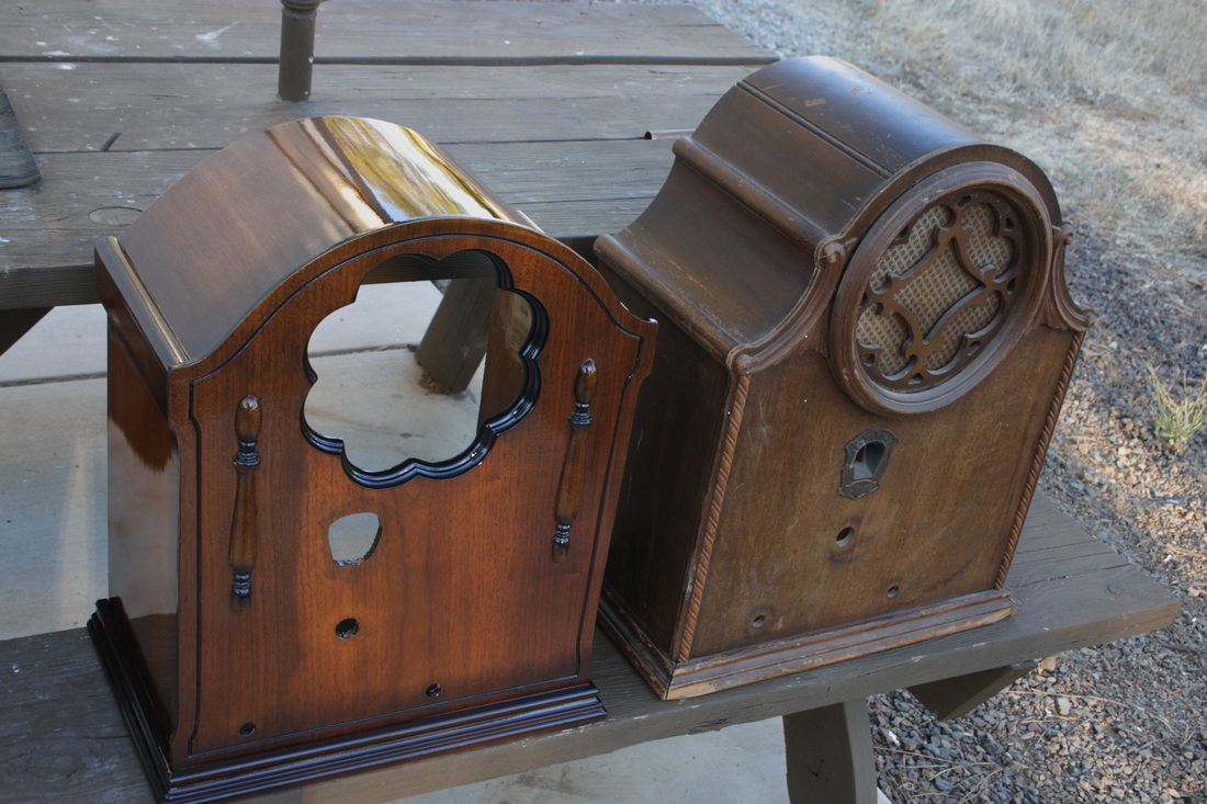 Both of these radios are from 1931. The AC61 has 6 tubes and the AC70 has 7. They are both seriously large and heavy even by 1931 standards.
As you can see the cabinet for the AC61 is almost finished (or refinished). I have cleaned up the chassis which is in great shape except for the replacement power transformer. I need to find an original one, good or bad, but the one that is there now can't stay, The AC71 cabinet only needs some trim made and a new finish. However the chassis and speaker are missing. So I you have a power transformer for the 61 or a chassis for the 70 just laying around, let us know. They are easy to ID with the off-center dial. |
AuthorRuss Webb 
Russ Webb & Fuzzy
Best Buddy, Radio fixer Categories
All
Archives
December 2023
|

|
|
 RSS Feed