
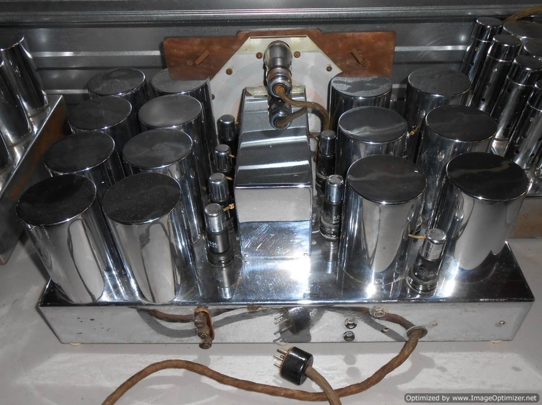
The Masterpiece V receiver chassis. Note the chrome grid-cap shields on metal tubes. This radio has 5 bands with a range up to around 65mhz. It has 20 tubes counting the eye tube. There is a BFO designed for CW. The audio output is two 6L6s into what was the 18" Jensen, gone now but I am using two Jensen A12s like in the Masterpiece VI, and added a separate tweeter.
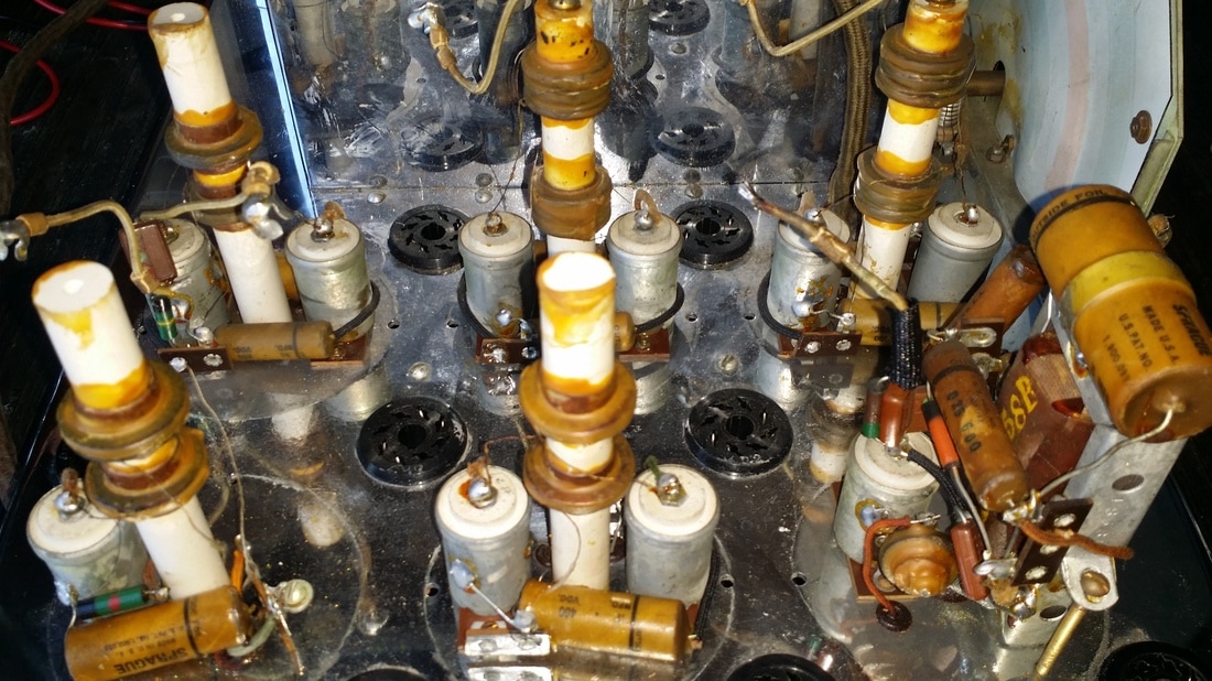
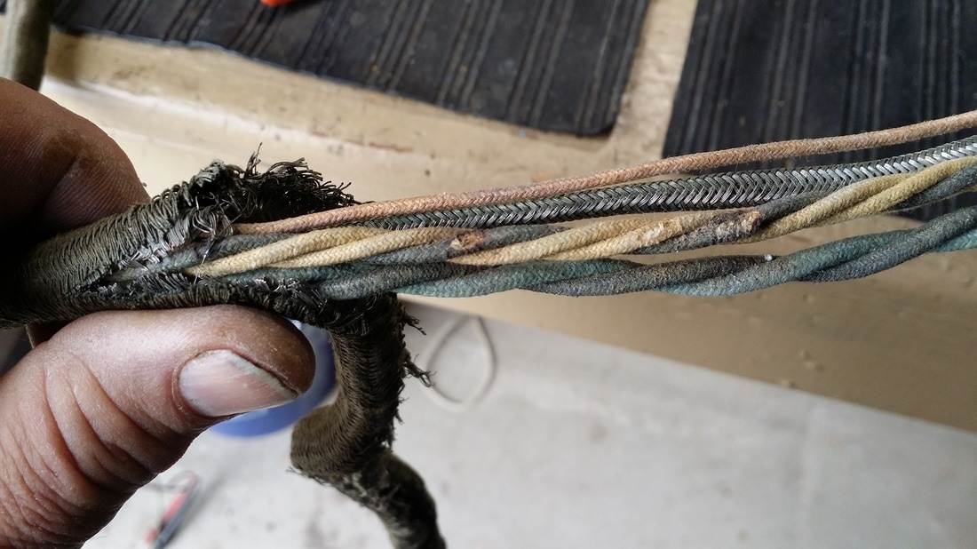
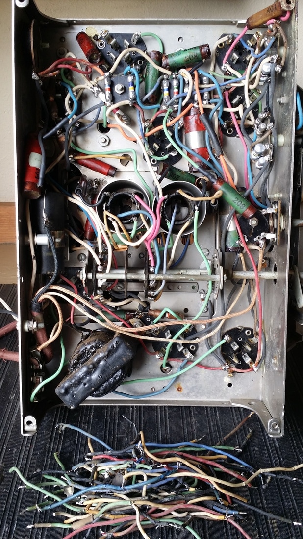
What is under all of those chromed shields? Better take a look if you are going to do a restoration - a lot of paper caps.
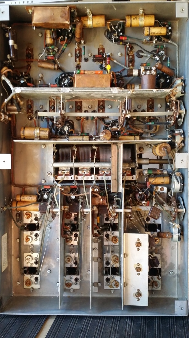
The underside of the chassis resembles a communications receiver such as a Hallicrafters.
Almost all of the original resistors were well within spec. This was a big contrast with the Strat chassis that I was working on simultaneously in which almost all of the carbon comp resistors were way out of spec.
Almost all of the original resistors were well within spec. This was a big contrast with the Strat chassis that I was working on simultaneously in which almost all of the carbon comp resistors were way out of spec.
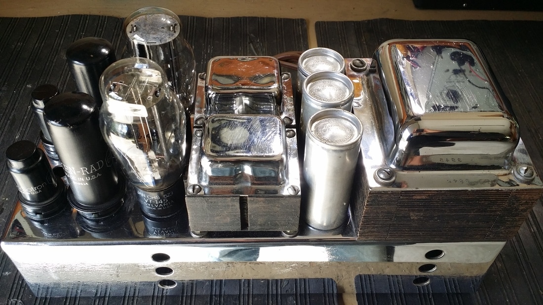
The power/amp chassis is also chromed. Not quite as nice as the main chassis but still presentable.
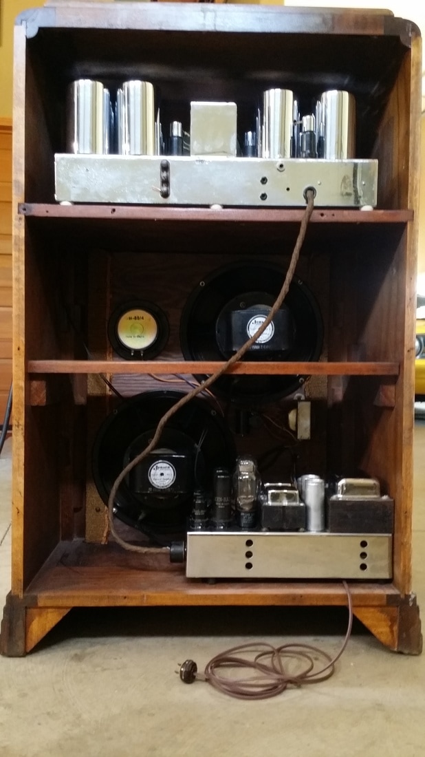
Back side
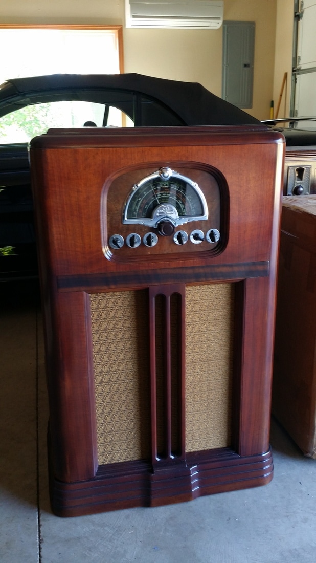
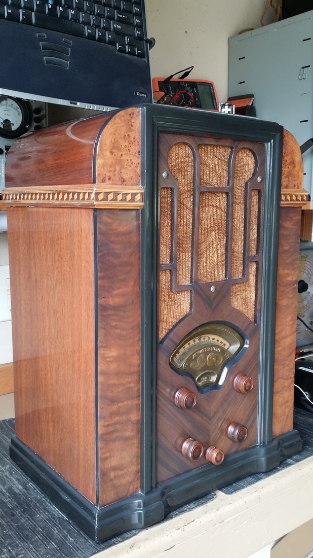
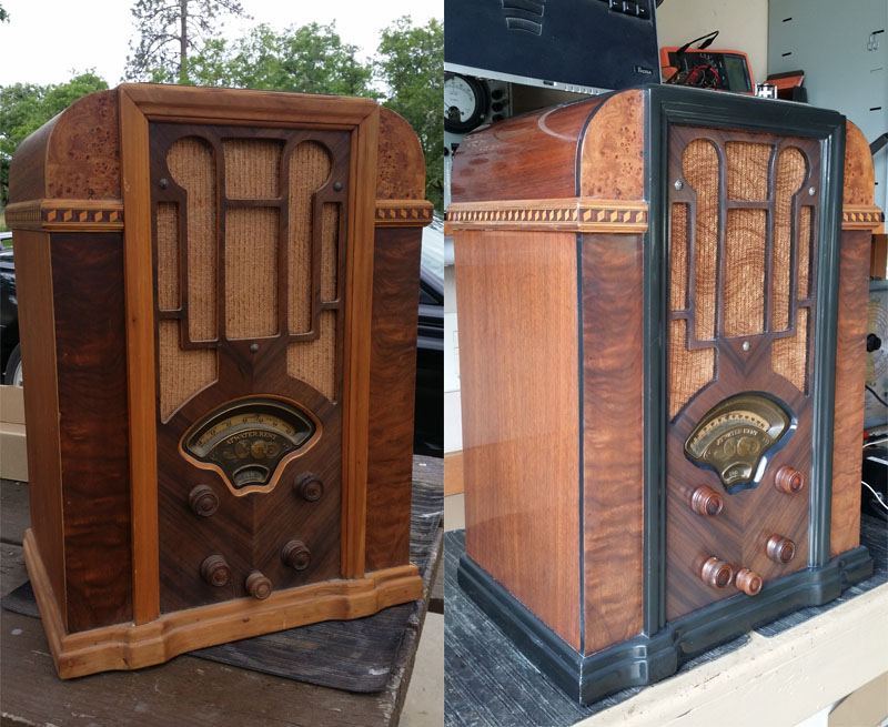
The 2 Jensen A 12 speakers were not original equipment (according to my friend Norman B.) but were included in the exchange as was the Oxford cabinet. This cabinet is most often seen with the later 15-17 model but since all cabinets were optional, any cabinet that fits is appropriate. A note, that it has been reported that the Masterpiece V will not fit in cabinets made for the 15-17 without removing the chromed cover is puzzling since the chassis fits very well in this example.
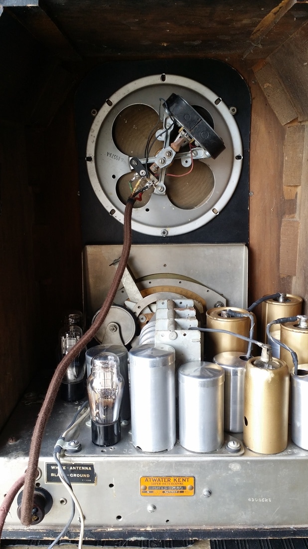
The shelf was drilled for a pedestal mount speaker, probably also an A12. The front baffle is new and all 3 speakers are mounted to it.
The two Jensen A 12s have different FC DCR. One being about 250 ohms and the other being 5K ohms. This is good and similar to the FC values on the original Jensen Super Giant. An additional 50W 1K ohm resistor is placed inline with the two field coils which drops the B+ to just the right value and keeps the FCs from passing too much current and getting hot. A pair of Jensens with 800 ohm and 7 or 8K ohm field coils would be better but very hard to find. A pair like these is still a challenge to locate and not cheap.
The 2 Jensen A 12 speakers were not original equipment (according to my friend Norman B.) but were included in the exchange as was the Oxford cabinet. This cabinet is most often seen with the later 15-17 model but since all cabinets were optional, any cabinet that fits is appropriate. A note, that it has been reported that the Masterpiece V will not fit in cabinets made for the 15-17 without removing the chromed cover is puzzling since the chassis fits very well in this example.
The shelf was drilled for a pedestal mount speaker, probably also an A12. The front baffle is new and all 3 speakers are mounted to it.
The two Jensen A 12s have different FC DCR. One being about 250 ohms and the other being 5K ohms. This is good and similar to the FC values on the original Jensen Super Giant. An additional 50W 1K ohm resistor is placed inline with the two field coils which drops the B+ to just the right value and keeps the FCs from passing too much current and getting hot. A pair of Jensens with 800 ohm and 7 or 8K ohm field coils would be better but very hard to find. A pair like these is still a challenge to locate and not cheap.
I think that the Masterpiece V is one of the best radios sold prior to WWII. Especially among those that were available to the general public (omitting some of the high tube count Scotts).
It will receive up to 65mhz, a real advantage over the Strat. This is probably a credit to the tube choices and the fact that the metal tubes were superior for RF circuits to the G type glass tubes in the Strat.
I set the 0-beat on the BFO while adjusting the IFs. It is very useful for CW signals. While the level of the BFO is not adjustable, a little careful tuning will allow SSB signals to be demodulated. This is also an option the Strat does not have.
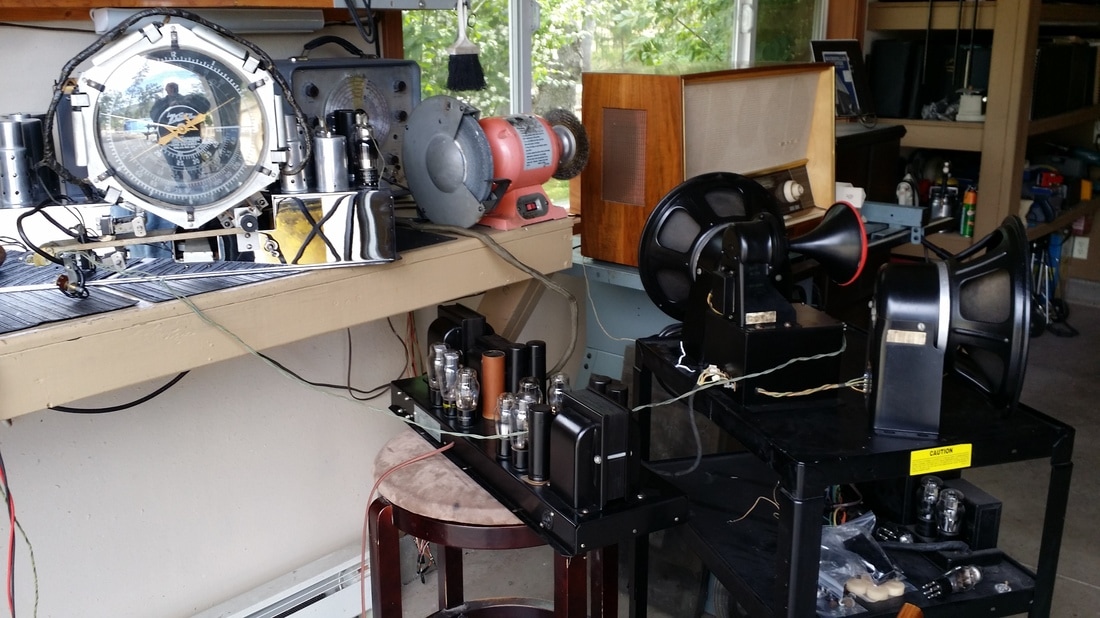
The audio is good, really good for 1935, yet in a comparison with the 25 tube Zenith it is not quite as impressive. It does have separate bass and treble controls (tone only on the Strat) but the treble is not quite as crisp and max bass is not quite as strong as the Strat.. In this respect the 8 45 triodes with separate bass and treble interstage transformers works well for the Zenith. Keep in mind that the 18 inch Jensen would probably have helped the bass somewhat, but I am comparing apples to apples since the Zenith was stock with two A12s and a tweeter - the same configuration I am using in the MSM-V.
Tuning is always on the fast ratio until you reach the desired spot and then you can slow tune back, using the same knob. Fast and slow tuning are separate controls or manually switched on most other radios.
There is an audio expander circuit. I'm sure it ads dome dynamic range to some music, but speech is a little weird with the volume going up and down. The expander can be switched off.
The same control will give you narrow and wide IF control. The wide IF setting would probably be used on strong broadcast stations whereas the additional 2 stages of IF selectivity are a real gain for shortwave listening.
The dial is easy to read and fairly accurate if aligned properly.
I would rather have the on of switch on either the tone or volume control but McMurdo used a separate switch mounted on the side of the cabinet.
If there is any interest, I could do a more complete comparison between the MSM V and the Zenith Strat and maybe the Scott 16 and/or the Philco 37/116 (though it is 2 year newer) and the GE M-125 (also from 1935) just for fun.
It will receive up to 65mhz, a real advantage over the Strat. This is probably a credit to the tube choices and the fact that the metal tubes were superior for RF circuits to the G type glass tubes in the Strat.
I set the 0-beat on the BFO while adjusting the IFs. It is very useful for CW signals. While the level of the BFO is not adjustable, a little careful tuning will allow SSB signals to be demodulated. This is also an option the Strat does not have.
The audio is good, really good for 1935, yet in a comparison with the 25 tube Zenith it is not quite as impressive. It does have separate bass and treble controls (tone only on the Strat) but the treble is not quite as crisp and max bass is not quite as strong as the Strat.. In this respect the 8 45 triodes with separate bass and treble interstage transformers works well for the Zenith. Keep in mind that the 18 inch Jensen would probably have helped the bass somewhat, but I am comparing apples to apples since the Zenith was stock with two A12s and a tweeter - the same configuration I am using in the MSM-V.
Tuning is always on the fast ratio until you reach the desired spot and then you can slow tune back, using the same knob. Fast and slow tuning are separate controls or manually switched on most other radios.
There is an audio expander circuit. I'm sure it ads dome dynamic range to some music, but speech is a little weird with the volume going up and down. The expander can be switched off.
The same control will give you narrow and wide IF control. The wide IF setting would probably be used on strong broadcast stations whereas the additional 2 stages of IF selectivity are a real gain for shortwave listening.
The dial is easy to read and fairly accurate if aligned properly.
I would rather have the on of switch on either the tone or volume control but McMurdo used a separate switch mounted on the side of the cabinet.
If there is any interest, I could do a more complete comparison between the MSM V and the Zenith Strat and maybe the Scott 16 and/or the Philco 37/116 (though it is 2 year newer) and the GE M-125 (also from 1935) just for fun.

 RSS Feed