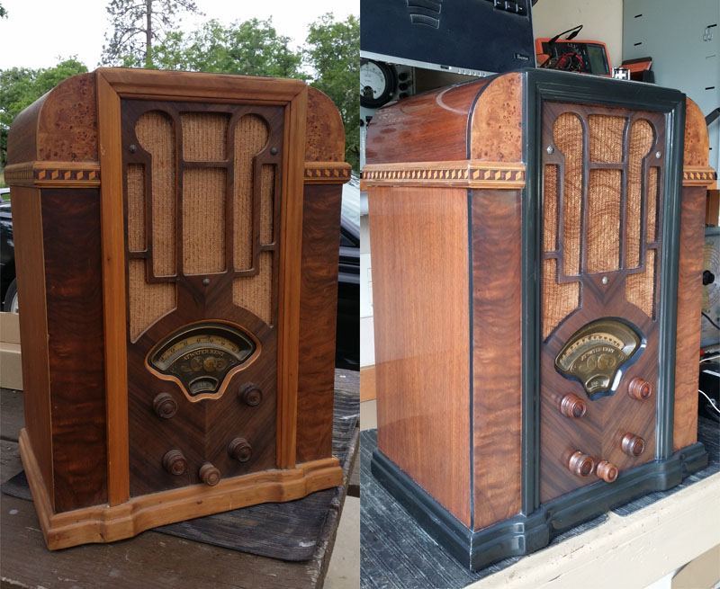
I had been lucky enough to have completed the AK 559N project a short time ago. This radio is also of that vintage with similar cabinet design as well as chassis design along with the associated common issues.
The 768Q is a 8 tube "farm" radio meaning that it was battery powered. In most circumstances, this was an effort to provide radio receivers to a large portion of the country that had yet to acquire commercial electric service in the mid 1930s.
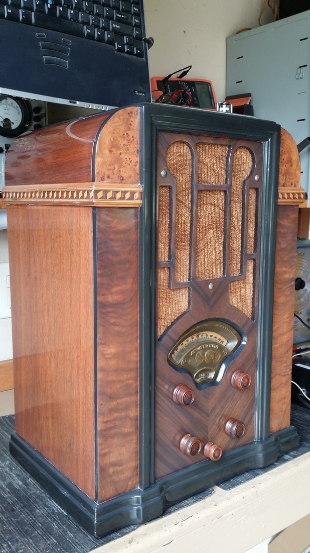
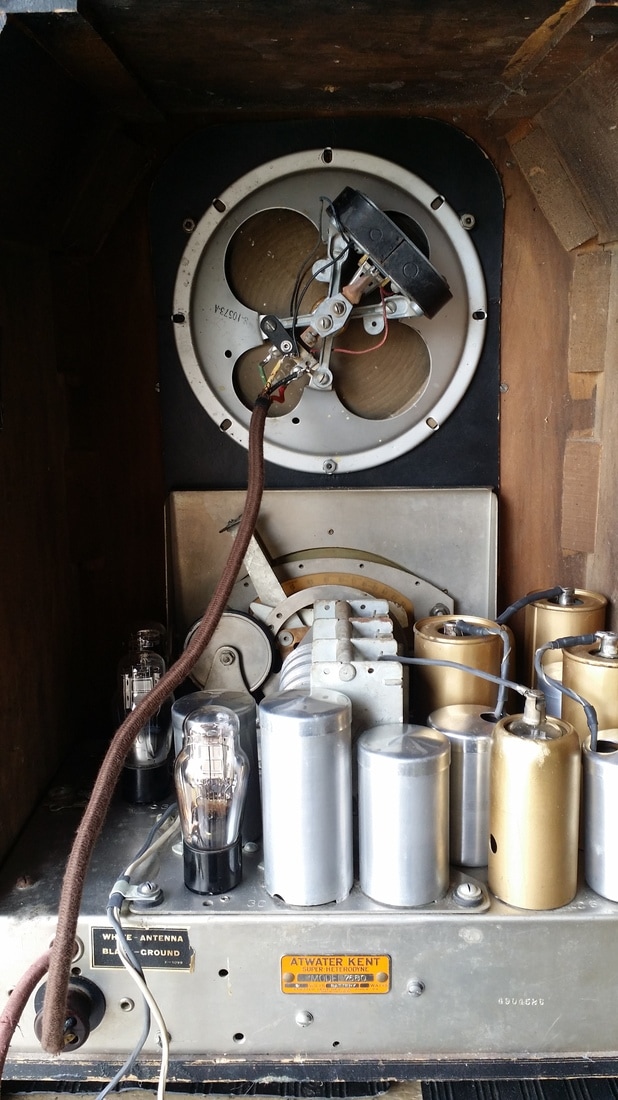
This radio shares a cabinet with other AK models such as the AK 447. Other than the power source, significant differences between these models include - tube count, the lack of a shadow meter and the use of a pin-type speaker using a natural magnet rather than a field coil. Most of these differences reflect the considerations that must be made to improve battery use economy. The addition of an additional tube also reflects this consideration. The 8th tube is in the audio output, the 768Q having push-pull 30s driving the speaker directly through a center tapped "magnetic" coil. This coil energizes the speaker accomplishing cone movement as compared to the voice coil in a dynamic speaker such as in the 447.
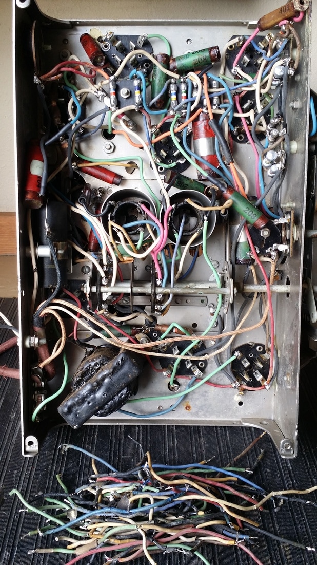
This chassis had survived storage very well, maybe better than any other AK of the period that I have worked on. Most of the original resistors were OK and the rubber wire was remarkably well preserved - estimating that only around 1/3 was cracked or had hardened insulation. None the less, I replaced all of the wire on the IF and RF transformers and the interstage transformer even if it appeared ok. Having the radio apart for service made replacement of the wire more practical now rather than waiting for it to fail and I did not want to take the transformers off again later. So all in all , I replace about 90% of the original rubber insulated wire with new neoprene rubber insulated wire of the same colors - or at least close.
As is often the case, the rubber insulation on the black wire was always bad and failure of other colors also tended to be similar in all examples. It seems that the pigment has something to do with the failure rate. Also degradation by mold/fungus seems to be a factor so wire that is isolated in a can or elsewhere usually is in better shape than the mass under the chassis.
Other than the cabinet being stripped/sanded, it looked like somebody had done a bit of poking around under the chassis, cutting a few wires, but nothing else.
The pin type speaker is of the same size as the original (there were two different models of speaker used in this radio). It is similar in appearance to one of the original speakers. It is not a dynamic speaker rather one that uses the lever action attached to a pin that exerts force on the cone. The "permanent" magnets are not permanent and often need repolarization. It can reproduce midrange frequencies pretty good but is very poor at reproducing low frequencies.
To make this speaker work ,I had to remove the winding (coil) and rewind it with a center tap which goes to B+ with both ends going to the plate of one of the push-pull number 30 tubes. A number 30 is a triode similar to a 01A but with a 2 volt common cathode filament. They are efficient but don't produce a lot of audio, so using 2 in PP was a good option.
The local distance switch is useful since it is easy to overdrive the front end increasing distortion. Testing using my AM transmitter required the switch to be in the local setting for best reproduction.
The radio has 3 SW bands with the upper band going to about 22.5 mhz. Reception on the shortwave bands is good.


 RSS Feed