
Most owners of old radios want them to work. After spending time and money on a repair or restoration many owners are disappointed with the content of modern AM broadcasts. After all, the signal/noise ratio and distortion of most "talk radio" broadcasts are a given - a lot of noise and distortion, even with a good signal.
Probably the best way to add quality programing to your old radio collection is with a low-powered, local transmitter broadcasting personally selected content.
Such devices have become inexpensive and, to some extent, reliable. Issues with these transmitters are usually associated with noise, interference and modulation levels/quality. There are at least two instances where using a Part 95 transmitter is not the best solution. First, those people with only one or two radios might not want the additional expense and the associated hardware for their small collection/display. More significant for us "serious" collectors is the inherent mediocre audio quality and it's reproduction on a very high end radio like a Scott, McMurdo Silver or any of the high tube count radios of the 1930's to the 1970's. It is difficult to get the performance that these radios are capable of without quality input.
Many of these high-end radios came with phonographs or at least a phonograph input that can be used with modern source equipment. The most significant drawback associated with using your MP3 device as an input is the relatively small signal voltage that they generate for audio output.
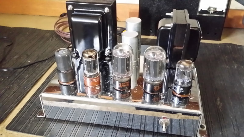
Above: A modified Scott 510 power supply/audio amp chassis
The other significant compatibility issue is that even the mightiest, 25 tube (or more) hi-fi system built prior to 1955 was only single channel (mono) reproduction. So even with a quality phono input, the question is - "So where do I plug-in this other cable". Using a "Y" adaptor that ties your right and left stereo channels together (with no isolation) is usually a bad idea and might even damage some devices.
The simplest solution in many cases is to build a matching transformer/cable using 2 small output transformers. This will provide isolation for the R and L channels of the MP3 device along with a voltage boost - and less than great frequency response. This is still a good choice if you have a phono input or can manufacture one.
What we have here is completely different.
First a little background: Mentioned below - and still lacking the story it deserves - is a collection of radios/chassis/parts donated to the cause in early summer of this year. Among these was a Scott 510. All of the components were there including the cabinet which was the typical, rectangular, late 40's box with a couple of doors - not my favorite design. This cabinet was originally finished in the white-washed color that was popular in the 1950's. Along with the yellow-ish finishes of the same period, also, not a favorite. The overall delaminated, banged up, falling apart condition contributed to the decision to not restore.
The receiver chassis used in the 510 is good, maybe even very good, but certainly not consistent with the quality and leading edge design of earlier Scott models. So, I scrapped that chassis too.
The remaining chassis is the chrome-plated power supply/audio amp seen in the first picture, above.
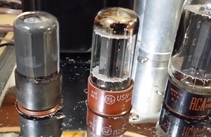
New 6SL7GT on left
This is a nice unit using a 6SN7GT driver and push-pull 6L6s for output. And look at the size of that audio-output transformer (8 ohms only). The published frequency response is 30 to 20k hz at +/- 1 db.
http://www.nostalgiaair.org/Resources/592/M0016592.htm
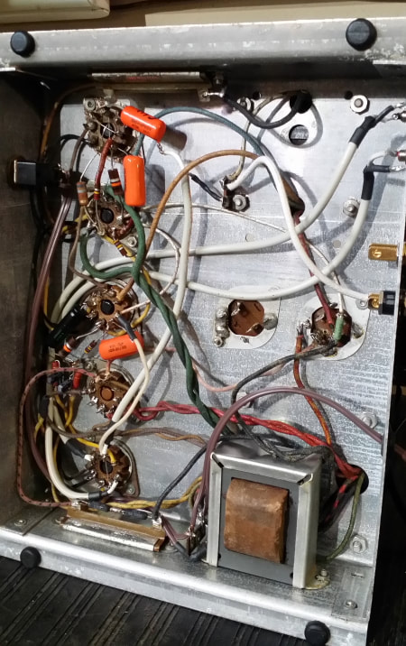
It was built with a dual power supply using both a 5y3GT and a 25Z6GT as rectifiers. The 25Z6 was no longer necessary since it only supplied the receiver chassis. There was also a nice large choke (underside of chassis) that was now no longer needed. Having recapped the unit, I decided that it would be nice to incorporate this choke into the amp's power supply. So I reduced the value of R48 from 375 ohms to about 275 ohms and installed the choke between the first and second filter caps.
Testing the amp using input from my Samsung phone, I found the output to be way too low to be satisfying. There was just not enough voltage out of the phone to drive the 6SN7 grids (in parallel). The extra, now unused rectifier socket was also screaming - "stick a tube here". So I did.
The objective was the same as stated above, to provide isolation, voltage gain and combine (mix) right and left channels. Since I had plenty of power supply overhead - lacking the need to power the receiver chassis, the obvious solution was the addition of a 6SL7gt stage prior to the 6SN7 driver.
So how is this done? Easy. Just look in the index of your RCA tube manual under the chapter on Resistance Coupled amplifiers. WHAT? You don't have a tube manual - don't tell anybody and get one here:
http://bama.edebris.com/manuals/tubesandvalves/
The directions are pretty simple. Pick your B+ voltage and desired characteristics from table 5 (I was using RCA 25 from 1966) and dig out the few additional parts that are needed. The drawing and specs are for a single triode. Your are just going to need to double this up for the 2 triodes in the 6SL7. The plates of both triodes will be tied together and feed the grid of the 6SN7 through a coupling cap also speced in the chart. Note that you could probably use a single cathode resistor/bypass cap, but I used 2, one for each cathode.
Most applications are going to need an additional tube socket and a person could use a 12AX7 but I already had a socket - given that it would probably be better further from the rectifier but that would require another hole and the 6SL7 that I chose had the aquadag coating which resulted in ALLMOST no hum. Rolling a few other tubes into this position resulted in some hum. I might add a shield - or not.
The test results were plenty of gain, good frequency response and little or no noise.
I also upgraded the 6L6s to 6L6GCs so that I could play with higher B+. As it is, B+ is running at about 380V. I added 2 shielded cables with RCA jacks to the back of the chassis. You might want to add a coupling cap of around .01uf to each input to the grids of the 6SL7 to provide some safety for your device should one of the grids fail and crash into the plate resulting in B+ going to your phone/device. Otherwise, isolation is good as is the mixing of right and left channels.
http://www.nostalgiaair.org/Resources/592/M0016592.htm
It was built with a dual power supply using both a 5y3GT and a 25Z6GT as rectifiers. The 25Z6 was no longer necessary since it only supplied the receiver chassis. There was also a nice large choke (underside of chassis) that was now no longer needed. Having recapped the unit, I decided that it would be nice to incorporate this choke into the amp's power supply. So I reduced the value of R48 from 375 ohms to about 275 ohms and installed the choke between the first and second filter caps.
Testing the amp using input from my Samsung phone, I found the output to be way too low to be satisfying. There was just not enough voltage out of the phone to drive the 6SN7 grids (in parallel). The extra, now unused rectifier socket was also screaming - "stick a tube here". So I did.
The objective was the same as stated above, to provide isolation, voltage gain and combine (mix) right and left channels. Since I had plenty of power supply overhead - lacking the need to power the receiver chassis, the obvious solution was the addition of a 6SL7gt stage prior to the 6SN7 driver.
So how is this done? Easy. Just look in the index of your RCA tube manual under the chapter on Resistance Coupled amplifiers. WHAT? You don't have a tube manual - don't tell anybody and get one here:
http://bama.edebris.com/manuals/tubesandvalves/
The directions are pretty simple. Pick your B+ voltage and desired characteristics from table 5 (I was using RCA 25 from 1966) and dig out the few additional parts that are needed. The drawing and specs are for a single triode. Your are just going to need to double this up for the 2 triodes in the 6SL7. The plates of both triodes will be tied together and feed the grid of the 6SN7 through a coupling cap also speced in the chart. Note that you could probably use a single cathode resistor/bypass cap, but I used 2, one for each cathode.
Most applications are going to need an additional tube socket and a person could use a 12AX7 but I already had a socket - given that it would probably be better further from the rectifier but that would require another hole and the 6SL7 that I chose had the aquadag coating which resulted in ALLMOST no hum. Rolling a few other tubes into this position resulted in some hum. I might add a shield - or not.
The test results were plenty of gain, good frequency response and little or no noise.
I also upgraded the 6L6s to 6L6GCs so that I could play with higher B+. As it is, B+ is running at about 380V. I added 2 shielded cables with RCA jacks to the back of the chassis. You might want to add a coupling cap of around .01uf to each input to the grids of the 6SL7 to provide some safety for your device should one of the grids fail and crash into the plate resulting in B+ going to your phone/device. Otherwise, isolation is good as is the mixing of right and left channels.

 RSS Feed