
I have accepted another Strat restoration project.
This radio belongs to Jeff, a long time local collector. He would like the chassis to remain as original in appearance as possible while still functioning like new. (Not too big of a challenge).
I believe this restoration to be critical in preserving the history of one of these iconic examples of American innovation and industrial prowess in the early years of radio. For this, I have made an exception to the "no outside projects" statement on the home page.
SO, here we go - -
This restoration may seem a little slow since I can only spend a short time over the bench on any day - getting old is a PTA, but this gives me time to accurately update this blog.
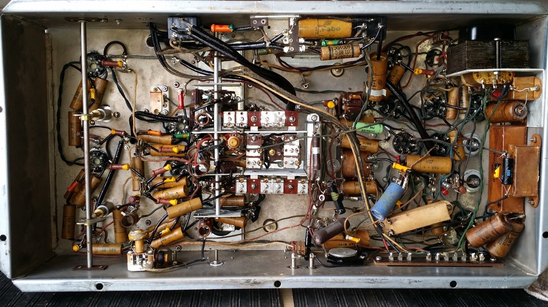
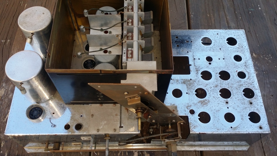
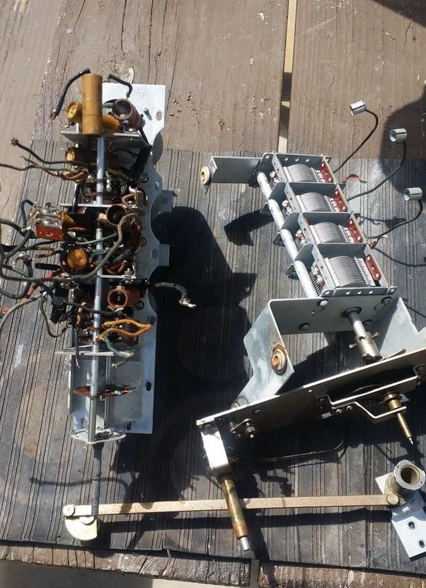
The 1000Z has 2 major chassis, The RF chassis (above) and the Power Supply/Audio Amp chassis. Additionally, the output/crossover chassis has some critical, custom, parts that must be serviced.
I have begun work on the receiver (RF) chassis and will post updates as the project progresses.
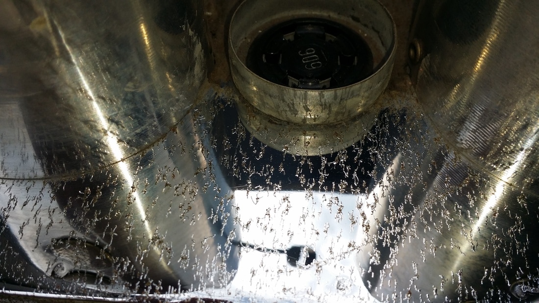
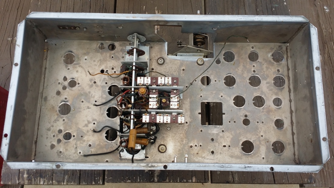
HOLD it right there - Well, after a closer examination, we have decided to replate (chrome) the receiver chassis. This is a huge amount of additional work, but it would be a shame to have the restored chassis looking like this:
This restoration may seem a little slow since I can only spend a short time over the bench on any day - getting old is a PTA, but this gives me time to accurately update this blog.
The 1000Z has 2 major chassis, The RF chassis (above) and the Power Supply/Audio Amp chassis. Additionally, the output/crossover chassis has some critical, custom, parts that must be serviced.
I have begun work on the receiver (RF) chassis and will post updates as the project progresses.
HOLD it right there - Well, after a closer examination, we have decided to replate (chrome) the receiver chassis. This is a huge amount of additional work, but it would be a shame to have the restored chassis looking like this:
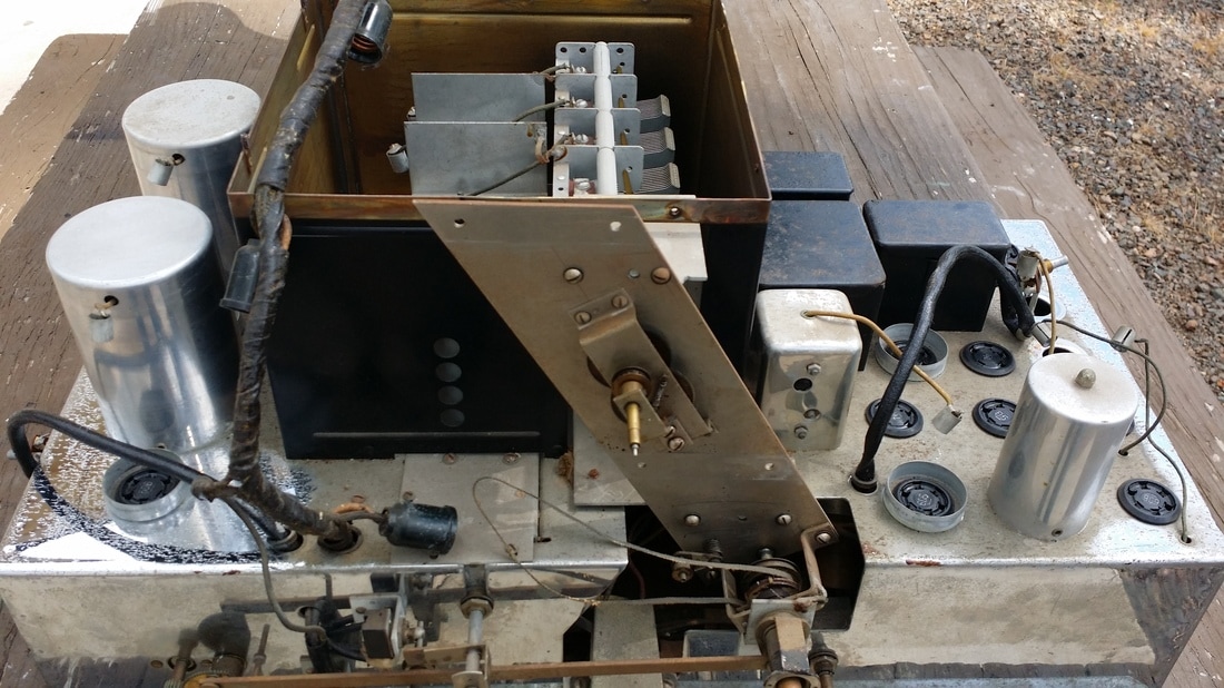
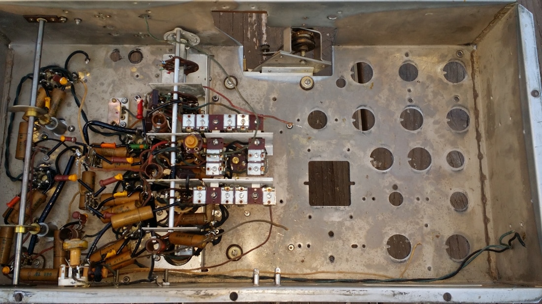
Today, the documentation and removal of ALL of the components from the chassis has begun.
The dog-bone replacement resistor kit for this chassis is finished.
Updated pictures as the chassis is stripped of all parts -
The dog-bone replacement resistor kit for this chassis is finished.
Updated pictures as the chassis is stripped of all parts -
Very few issues have ben found so far - which is nice.
One of the filter caps has blown the top off - will have to fix or find replacement.
The relay that enables/disables the audio in the muting circuit has an open coil (just like on mine and I suspect many others). It will be rewound.
A few of the original "paper" caps have been replaced - I will use the artwork created in the earlier restoration to build correct-looking replacements.
Chrome - as noted above.
Further deconstruction and testing reviled an issue with one of the interstage transformers.
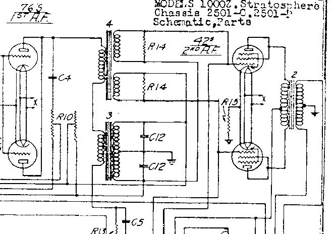
Portion of the schematic form Nostalgia Air showing the relationship of the 2 interstage transformers
Note that two 76s drive two 42s driving eight 45s (not shown).
Below, the deconstruction process continues.
Note that two 76s drive two 42s driving eight 45s (not shown).
Below, the deconstruction process continues.
The tube sockets are secured by a snap ring. This means that the sockets must be unwired before they can be removed from the chassis through the top.
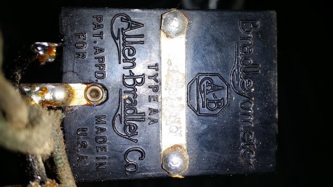
These are the Bradley volume and tone controls. The volume control includes a section for base contour (loudness) that increases the bass level as volume decreases and decrease base as volume increases until about 3/4 volume. At this point the base boost is nil but still controllable by the tone control.
I have not seen these exact units in any other radio. It would be fair to say that replacements would be very valuable. There is no indication that these are damaged.
The trip lever on the shaft of the volume control is used to switch the radio on/off. Needing to switch 350W, I believe that a suitable combined volume on/off switch was not available.
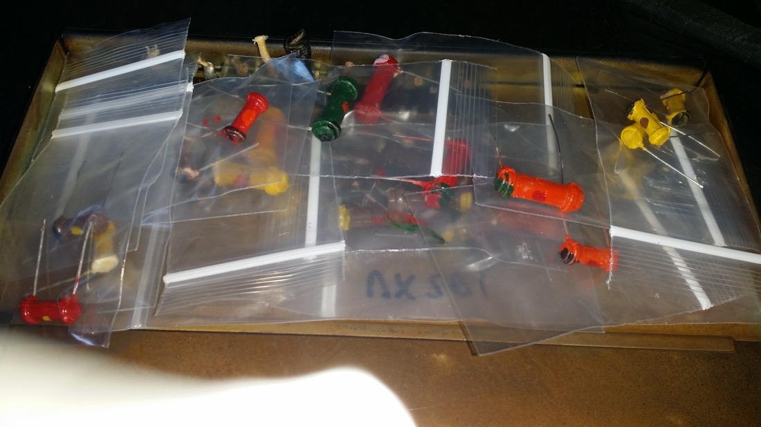
Resistor kit for the receiver chassis below. Even though some of the original dog-bone resistors were 1/4 W the replacements are no smaller than 1W, mostly 2 & 3 W (regardless of size).
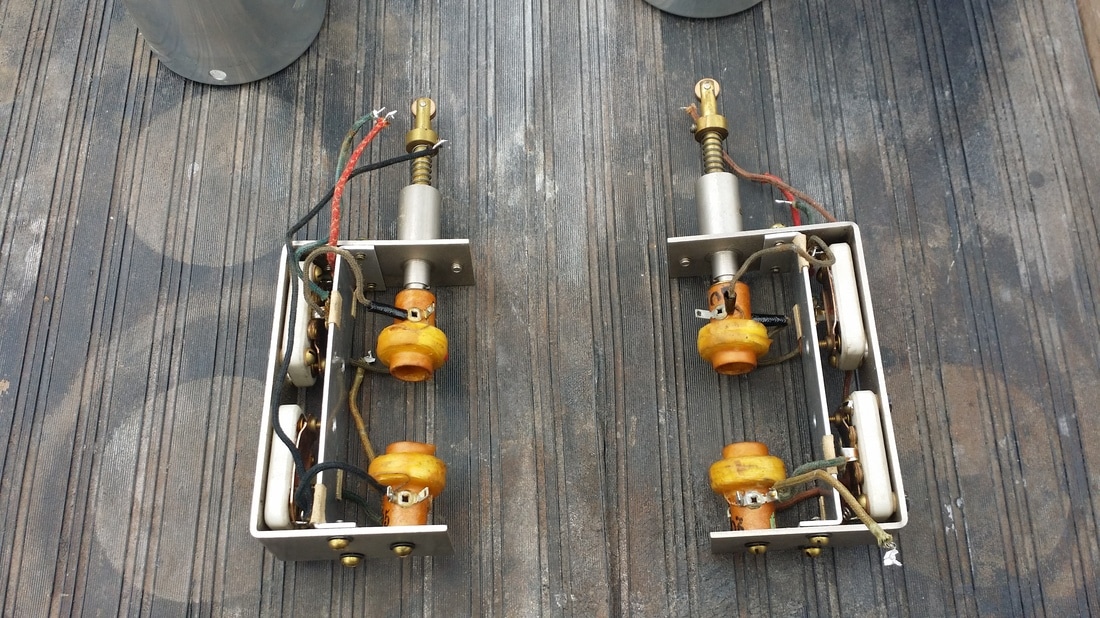
Below are pictures of the variable bandwidth IF transformers and a video showing the mechanics of their operation. Wider IF bandwidth allows the radio to detect more of the modulation resulting in better fidelity which is quite noticeable in the treble range. The drawback is worse adjacent channel rejection. You might also notice that a signal is slightly stronger when the IF is set to wide.
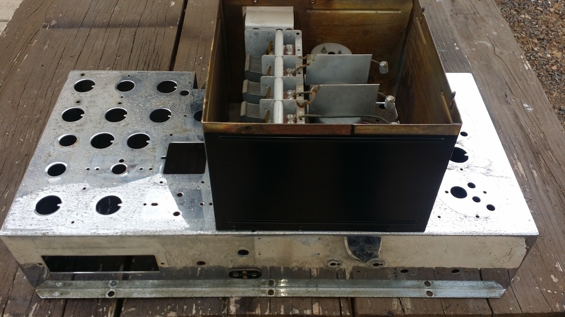
Only things left now are the tuning cap and band switch. I had left the shield on to protect the cap, but it can come off now.
The deconstruction is done. I can work on repairing the defective parts and on the power/amp chassis while the main chassis is off to the chrome shop.
Band switch and tuning cap removed.
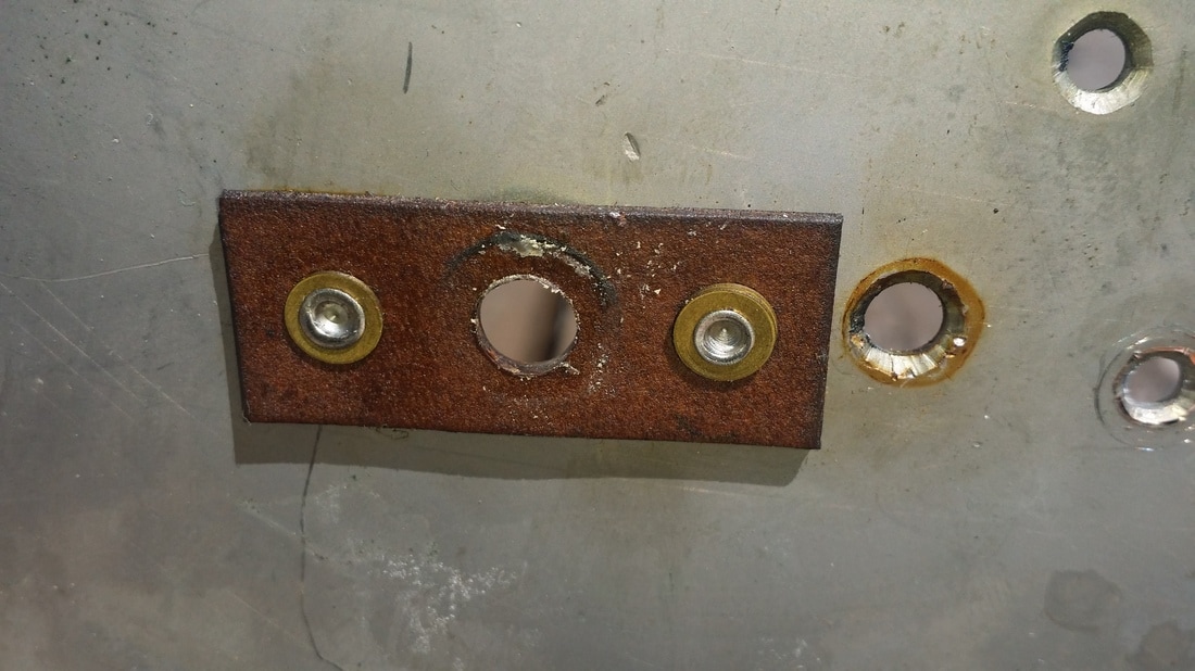
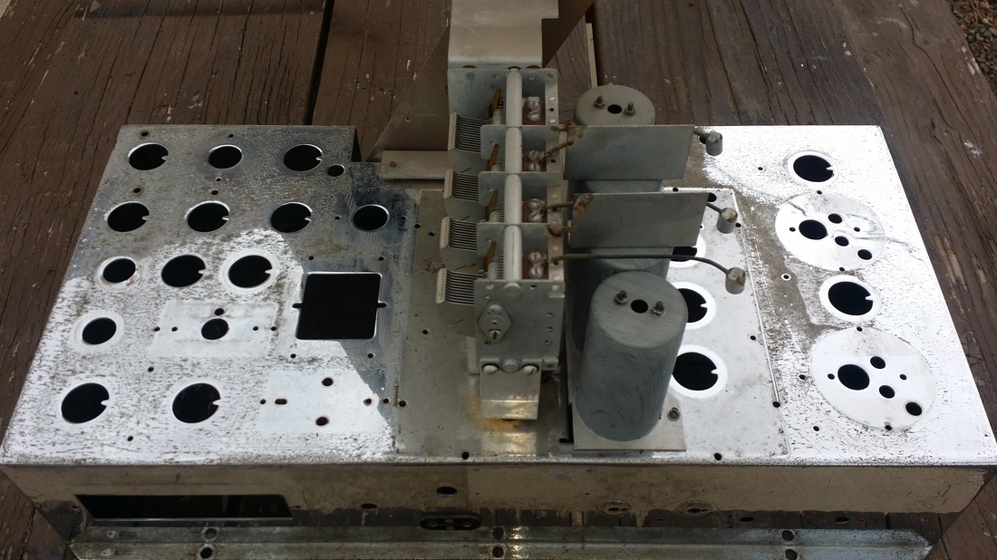
Needed to drill out a few rivets. Above, fiber guides for the variable IF adjustment shaft. AND - NO, I didn't drill out the holes to the right. This seems to be factory. Maybe they needed to enlarge the holes after the original plating process.
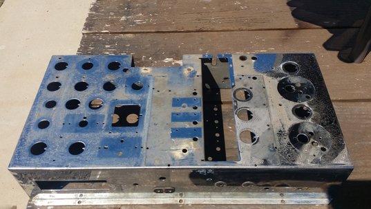
Receiver chassis all ready to go off to the plater's.
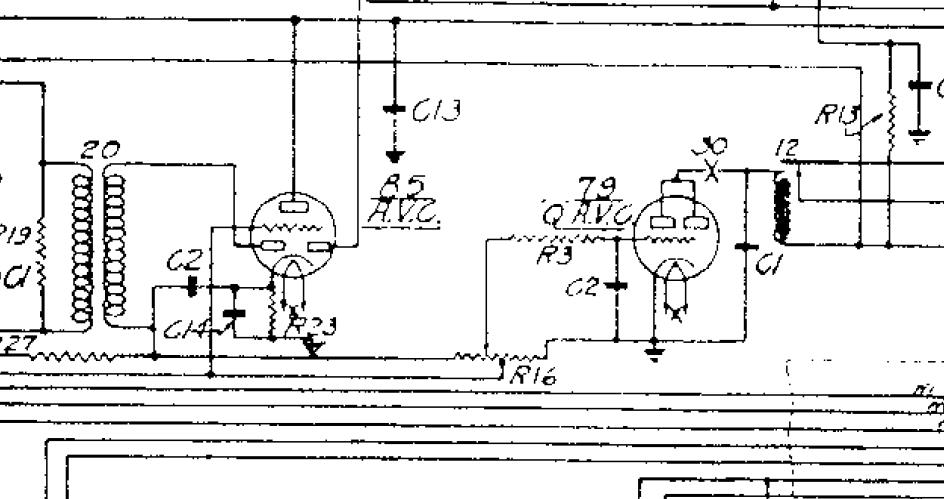
Above is the QAVC circuit being discussed in the comments (below). The relay is item 12. Courtesy of Nostalgia Air.
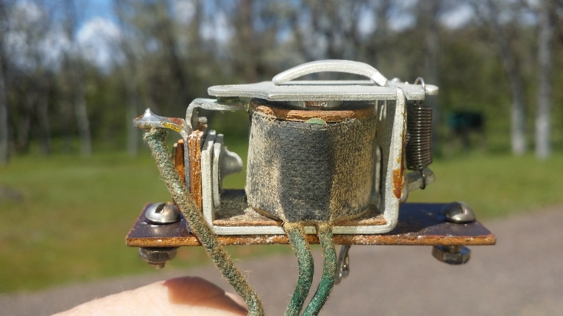
QAVC relay, still needs to have the coil rewound.
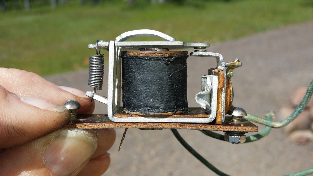
Here is the QAVC relay with it's new coil.
At this point, I am going to begin work on the power/amp section and will start a new blog entry.
At this point, I am going to begin work on the power/amp section and will start a new blog entry.

 RSS Feed