In the previous post the substitute UV 199 tubes are demonstrated in an early 1920s TRF radio. Now I wanted to test the UX 199/UX 120 versions along with another application for the UX 201A version.
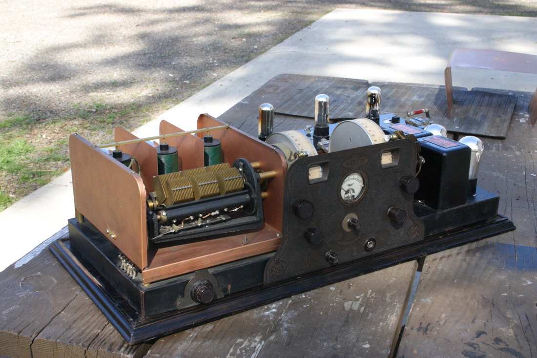
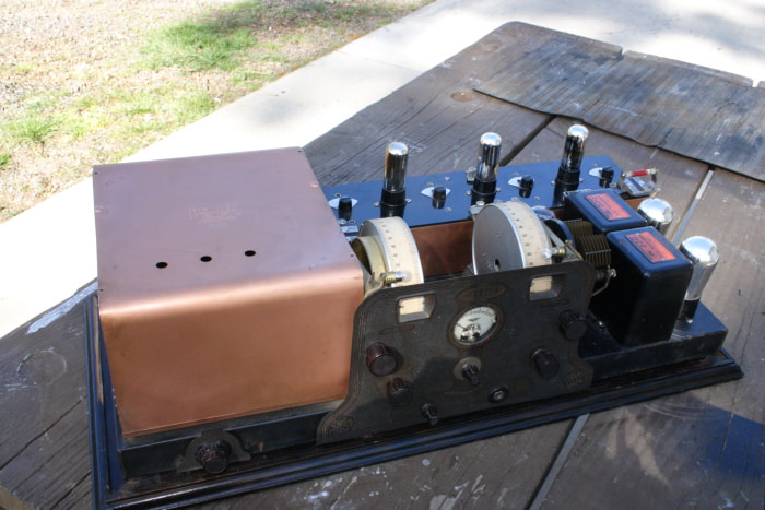
I realized that there aren't many - any, small radios using the later UX tube versions in the museum display. There are a couple in storage, not easy to get to. There is the Thompson Minuet, I really did not want to pull it off of the shelf and risk damaging the speaker cone that Buford Chidester made for it. And then there is this really big Remler super. Well at least the top cover was already removed for display.
The Remler is a cool radio!
I had purchased it about 5 years ago along with about a dozen other radios at an auction near Portland. It always seems that radios come in bunches and I am always in a hurry to clean them up. I do test them, but, generally move on to the next one after as quickly as possible.
Now I had a little time to explore and the first thing I needed to do was verify that the unit was functioning normally. It Wasn't. The second RF section in the TRF wasn't contributing at all.
It did not take long to find the problem which was a relief since there are a lot of moving parts and the potential for broken wires, but that was not it,
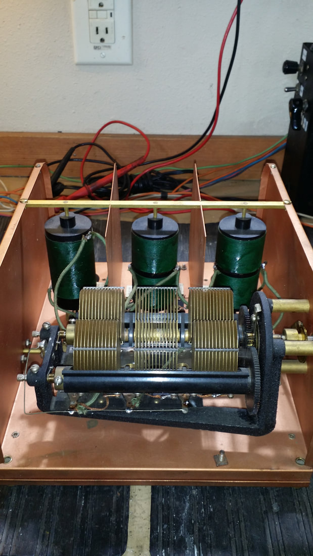
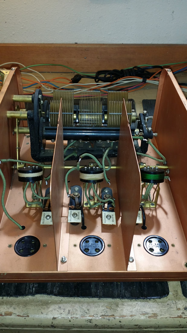
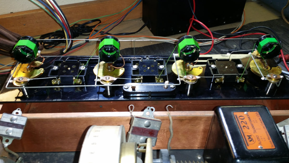
The second section of the tuning cap was shorted. This was not from broken parts but because of a wiring issue. The 3 sections of the ganged cap are isolated from each other until that little wire, seen near the bottom of the picture above is installed. On most tuning cap assemblies the moving plates (rotor) are all grounded to the shaft that moves them leaving the stationary plates (stator) to be connected in the grid circuit. On this assembly Remler had wanted to stagger the grounded plates - in other words the moving plates (rotors) in the center section were grounded. This must have confused somebody WHO grounded the stator as well as the rotor. I could tell from the obviously factory connections on the trimmer what the design configuration was.
I suppose that at This point I should explain that unlike any other early super that I have seen, This radio will operate as a superheterodyne OR as a TRF. And that is one of the reasons that I think it is so cool. With a "normal" super from this time you would tune and tune listening for a squeal and then tweak the IF and oscillator until you had a station. OR you would just have some noise - start over. On this radio you can turn up the TRF filament rheostat and get the same functionality as a 5 tube TRF, which is what it is in that setting. When a station is found turn down the TRF (you don't need that much input to the IF section) and adjust the super for the best audio. It really is much easier.
If you want to understand the other cool functions, like the IF that uses the sum of the freq. and local osc. there are a few good sites. Start at this one:
http://www.duanesradios.info/html/infradyne_superheterodyne.html
Now on to the tube substitution.
Below is a demonstration of the Infradyne:
Using the tree tubes there is a savings of 1/3A in the filament supply.
I used a 3S4 just to see if it would work, it does, but the 3V4 is probably better. In the case of the 3S4 the jumper between the plate and screen could be replaced by a resistor to reduce the screen voltage which is not required in the 3V4.
Well, this concludes this project, at least for now. I have another chrome plated monster to work on.
Russ
P.S. Don't miss Part I below.


 RSS Feed