Watch Your plate current.
Take care in bias settings.
And don't run your filaments too HOT!
Take care in bias settings.
And don't run your filaments too HOT!
I think it still has vacuum - or at least it did for a while.

|
|
|
Watch Your plate current. Take care in bias settings. And don't run your filaments too HOT! I think it still has vacuum - or at least it did for a while.
0 Comments
Hickok I-177, Military Tube Tester from 1953 Predecessor to the ever popular TV-7, this is a VERY tough, compact unit - until you add the adaptor for more "modern" tubes.. It has a switchable GM value function. It came complete with instructions and a tube testing chart which lacks any GM (mutual conductance) values. This may have been intentional to simplify testing. The instructions give the parameters for the pass/fail (red/green) tests.. I suspect the GM settings were covered in a more comprehensive manual which was not included in this set. All of the interior components and wiring were treated for fungus resistance. The benefit of this, beyond the lack of any moldy smell, was to preserve the components in a nearly new condition including the wire colors. 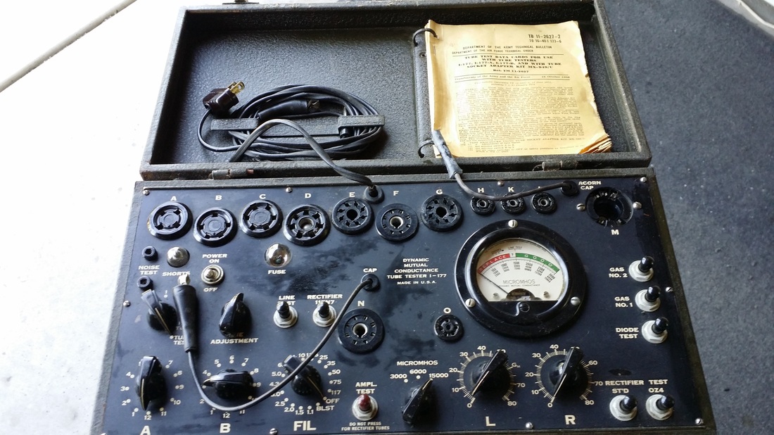 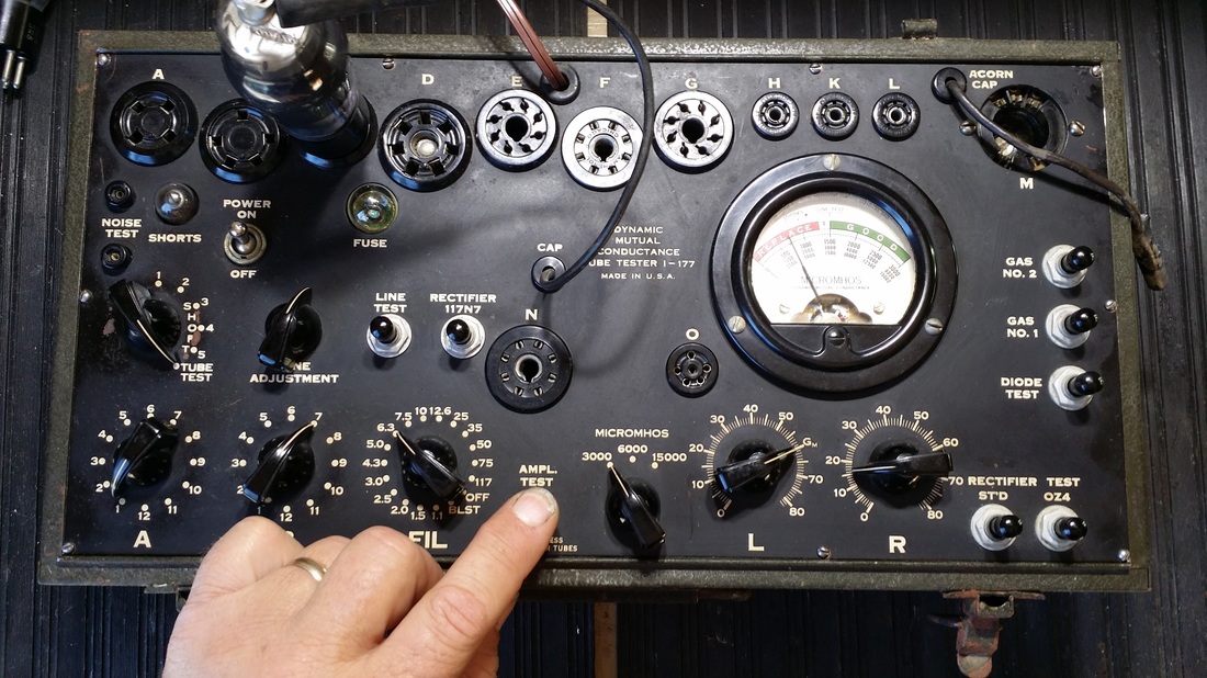 The adaptor, which includes more tube sockets and convenient pin straighteners. 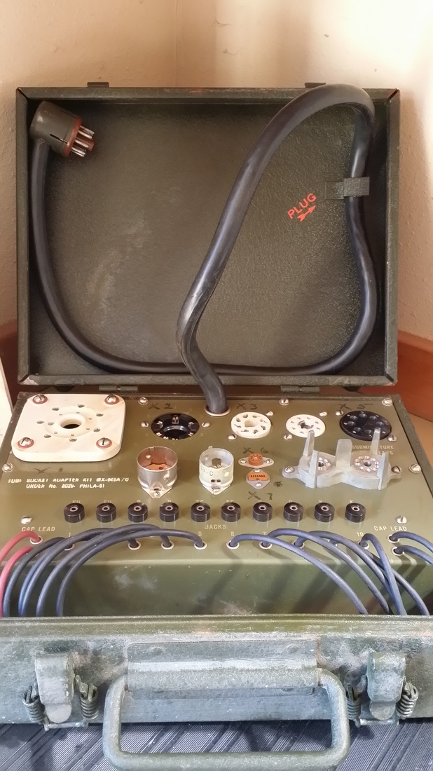 The tester seems to give results nearly consistent with my Hickok 600. It's shortcoming is a lack of any adjustments for calibration.
An interesting note "d" in the chart for most rectifiers, says that the best test is in circuit. OK! Let's get this thing going! 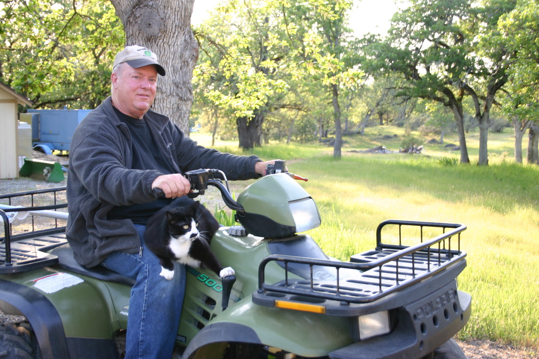 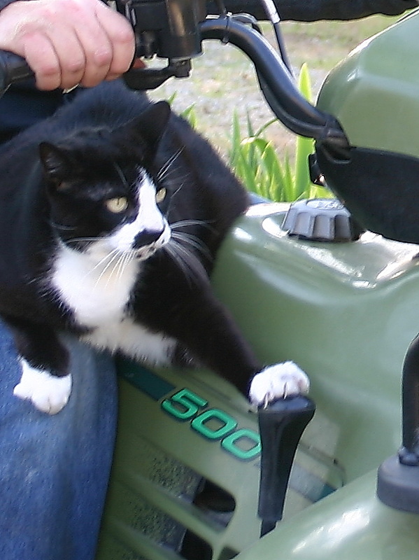 Fuzzy shiftin' into high gear.
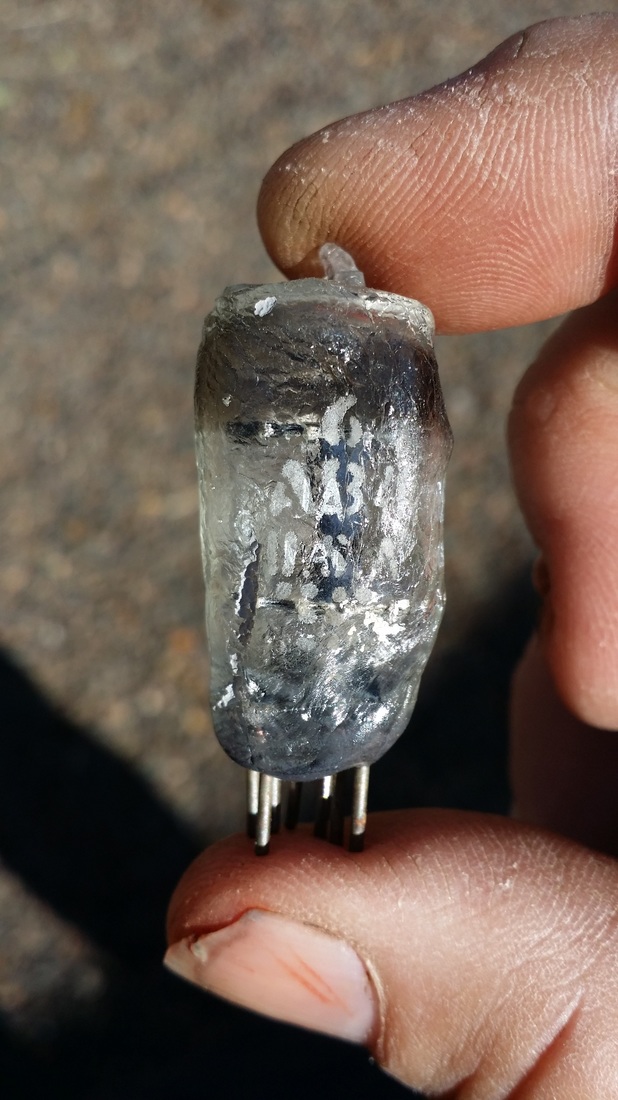
Hard to believe that we have any time for anything but old radios?  Book Review Reviewed by Jack Magnus for Readers' Favorite Sand in My Pants is a travel memoir written by Sue Webb. The author and her husband decided that they would take up scuba diving, and they did in a big way. At the time they obtained their certifications, they were living in the Portland, Oregon environs, so they had lots of diving opportunities both in the immediate vicinity and further up in the Pacific Northwest. Balancing those relatively chilly dives were their traveling adventures in search of warm water, reefs and colorful displays underneath the waves. Their travels took them literally across the globe: to Fiji, Australia, the Caribbean, Micronesia, the Florida Keys, and down the Pacific Coast to Baja California. Along with the dives, there were miles of beaches, hiking trails and muddy roads to explore, and a multitude of friendly faces who welcomed the two explorers on their travels. I knew I wanted to read Sue Webb's travel memoir, Sand in My Pants, when I saw it. I'm just getting into snorkeling and wild swimming, and am finding swimming with the fishes both exhilarating and addictive. Webb's stories of crystal blue waters and colorful reefs held me enthralled for hours. Her storytelling is filled with excitement, curiosity, and a determination not to take things too seriously, and the places she describes are marvelous. I kept making notes to myself of travel destinations I'd like to visit and beaches to explore. The author and her husband accomplished a prodigious amount of diving and exploring in the twenty-year period covered in this travel memoir and, for the most part, it seems they picked all the right places - even if a few didn't quite turn out as expected. I had a grand time reading Sand in My Pants, and I highly recommend it to both armchair explorers and those who love water sports.  Sand in My Pants by Sue Webb Non-Fiction - Travel 167 Pages Reviewed on 04/13/2015 This very gassy 280 is on the tube tester. The filament is set at 6.3 volts, too high for an 80 but required to get this kind of light show from a very gassy tube. Needless to say, this tube would be a disaster if it were installed in a radio. The purple glow is a good indicator of gas in the tube. Normally this would be contained in the area between the hot cathode and the plate. But in this tube a small aurora is generated as I switch sides, energizing first one plate then instantly switching to the other. Don't ask me why I tried this, and, of course, don't try this at home without proper adult supervision. Another of my favorites, a very gassy 224. 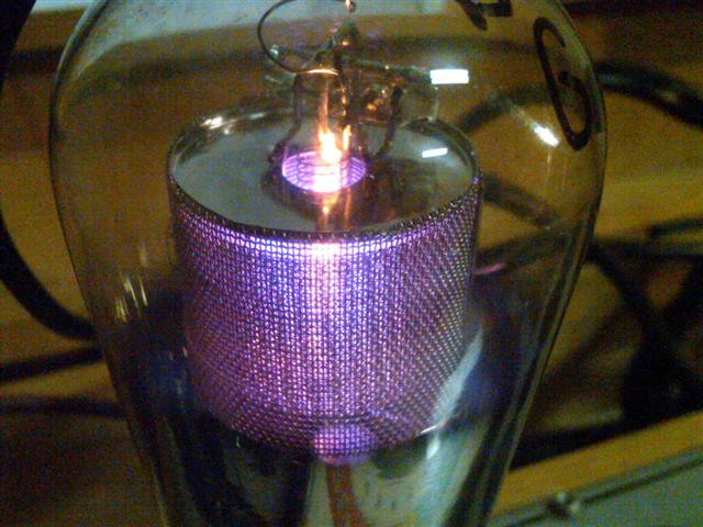 Don't confuse the deep BLUE glow clinging to the outside of the plates on your tube-amp's output tubes with these above. It is, in most cases, perfectly normal.
Arborphone from 1927 I find this cabinet design somewhat inspired as compared to the regular 1920's "breadbox". It was offered by a collector on ARF. As found - below: Credit for the first and last pictures to the seller. 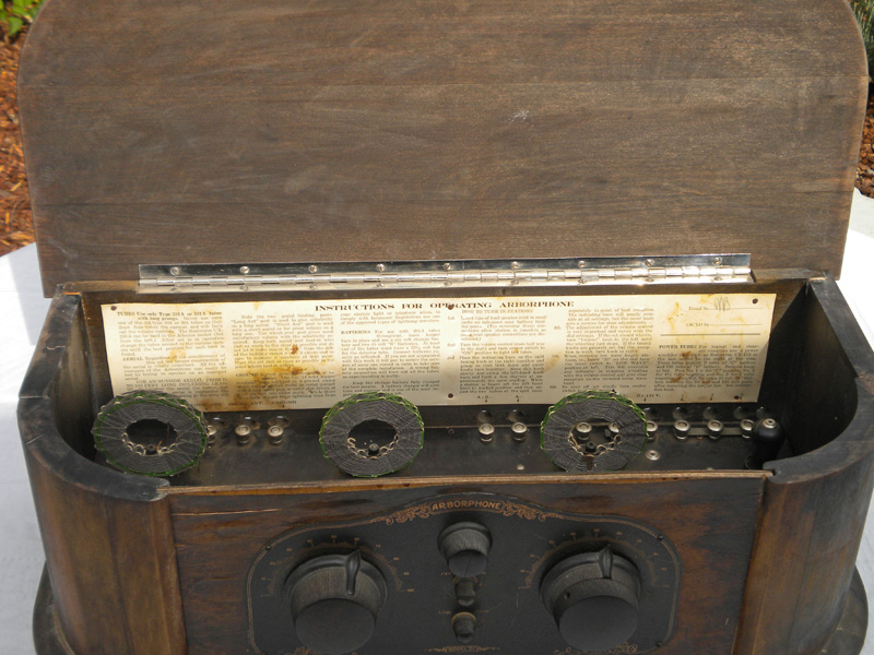 The cabinet had to be taken apart and reassembled. Taking it apart was not too challenging since there was not much holding it together. I was lucky, the solid wood sections had not warped too much, considering the delamination of the front veneer. It also had an open on one of the interstage transformers, which I rewound. I just could not get a picture that does it justice. Must have been the lighting.. 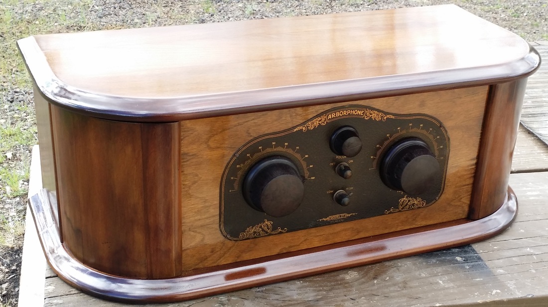 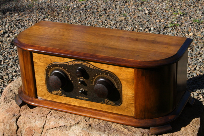 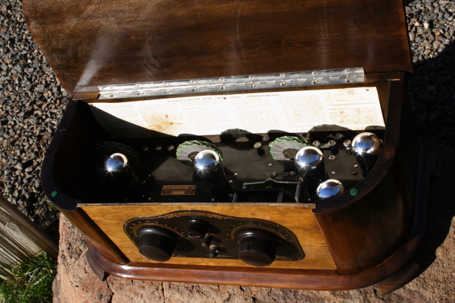 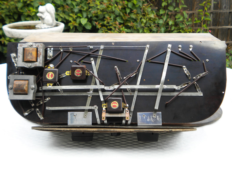 There was an auction the last Saturday of February in Salem. One hundred and forty plus radios from the Mike Parker Collection were up for bid before a crowd of around 100. It was a great collection of radios from the 20s and 30s with a large number of early battery powered sets. Story from the local newspaper: http://www.statesmanjournal.com/story/opinion/columnists/capi-lynn/2015/02/17/vintage-radios-auctioned-antique-powerland/23583773/ The auction was presented in association with the Northwest Vintage Radio Society. https://www.facebook.com/NWVRS It was a long drive but turned out to be very worthwhile. It was also good to see such a nice collection going to people that could appreciate them. Those that I was lucky enough to acquire are already on display in our museum. Here are some pictures and video of most of them. "Most" meaning, I had to buy two radios to get the chassis and cabinet for one, so there is still one chassis left over. One of the great things about this collection was that there were a number of "locally manufactured" radios. Remember that Oregon is a big State and I consider any radio made within it's boundaries, local. Come to think of it, Northern CA is also local. There were several radios from the Bay Area. Most of them needed a few caps replaced and there were a few open interstage transformers, but nothing too challenging. Remler Infradyne from 1928 This radio was sold as a kit, though kits may have been assembled by third parties. There is a lot of info on this rather scarce radio, manufactured in San Francisco, on the web. 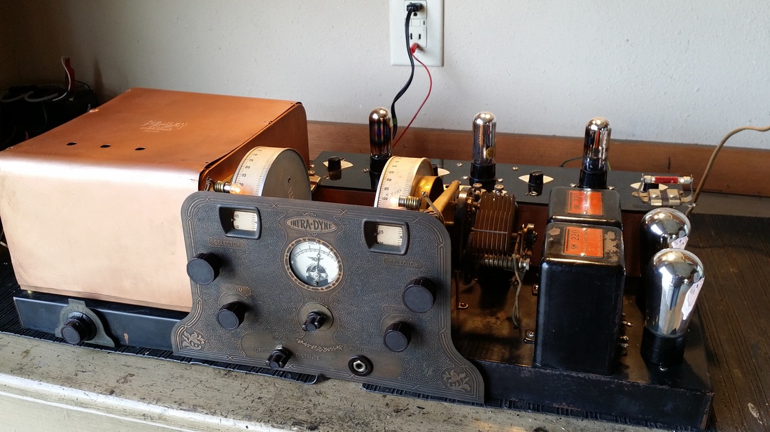 It has a very unique application of the super-heterodyne principle applied in the form of a module which is seen towards the back of the chassis with three 199 tubes on top. 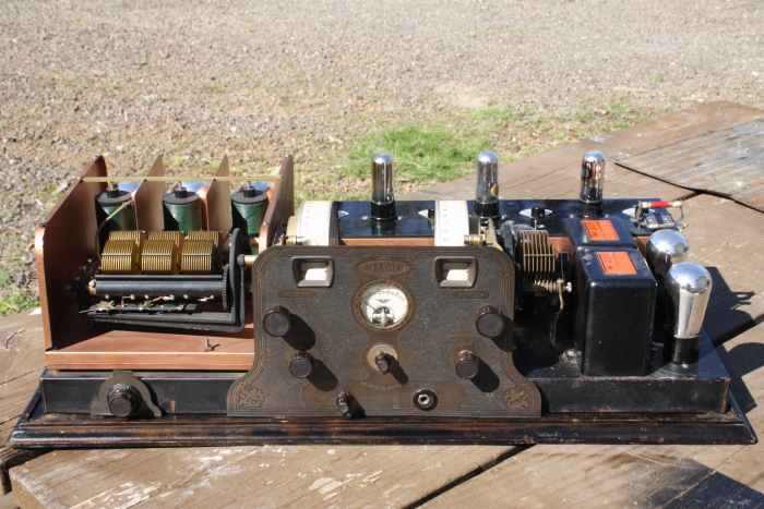 It seems to me that Remler tried to use nothing but the finest components in assembling this radio (kit). The main chassis is copper as are the sub-assemblies, the TRF tuner on the left and the Infradyne (super-heterodyne) module in the back. The audio transformers are labeled Silver Marshal. The exquisite tuning cap incorporates a mechanism that rotates a secondary coil within the primaries of the TRF receiver section. Tuning - well, is a learning experience. It says in the manual that the TRF section may be operated by its self in the "local" mode. And, it can, as long as there is a very strong local station nearby. In the local mode the Infradyne module and its associated 2nd detector (301-A) are not used nor are those tube filaments lit. In the "Distance" mode the performance of this receiver is excellent. One note, however. It was customary at the time to mark station settings on the tuning dials with a pencil. This was to make the tuning process easily repeatable. I see that there is only one station written on each of the dials. Either the user only received one station or ,more likely, he discovered that almost any other adjustment or change in any of the voltages will move the position of the station on the dial. So making notes was somewhat useless. The meter is for setting the 3 volt filaments on the 199 tubes. It will allow the filament voltage to run up to about 3.5 volts which will increase audio and necessitate retuning the module, but, is unnecessary. Setting the meter on 3 gives you a filament voltage slightly above 3 volts and that is about right because the manual instructs you to set the meter at that point. I have seen the 1927 version with a SM 221 OP transformer. This one has a spot to mount one, but it appears that one was not used and it is not in the 1928 schematic. Seems like a step backwards, but it works just fine using a high impedance speaker from the 135V B+ to the 112A second audio plate. A demonstration: Grebe Syncrophase MU-1 1925 This is one of the later model Syncrophase radios that incorporates the chains that mechanically couple the tuning caps. It sold for only $100. You can't get a del like that every day so I could not pass it up. Long Model B-5 from 1926 This is one of the radios that was manufactured in the Portland OR area. Not a lot of information is available on this radio manufacture and there is no listing for the radio in the Riders manuals. Probably, few were produced. 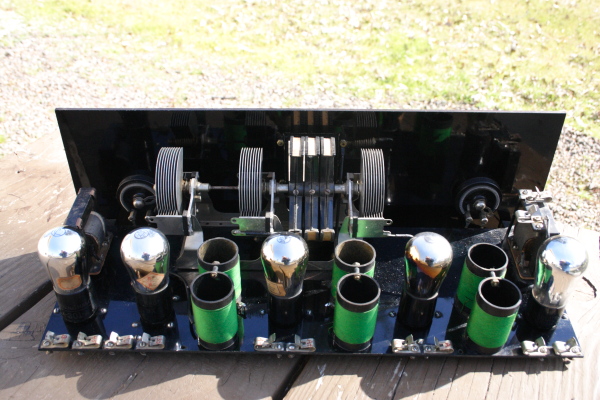 It is a 5 tube TRF with a 112A in the final audio position. The tuning dials are a little unusual and give the control panel a less cluttered appearance. 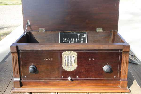 Rick Ammon. Sent me this follow-up information on the Long Radio Works. Copied from an email from Art H. R. (Portland 8-2005) : Probably built by the "Long Radio Works" by brothers Les or George Long on the family farm on Rural Route 1 (later renamed "NW Long Road"). This location was 20 miles west of Portland, Oregon or 1 mile north of the town of Cornelius, Oregon. They were in radio business from 1920 through the late 1930s. Below is a link to Ricks site which includes pictures of both a Long Radio Works Super Heterodyne and another radio produced in the Portland OR. Wish I had a few of those! http://superhets.info/page5.html Browning - Drake 5 - Tube Impedance Coupled Receiver This radio was a kit. It was assembled in Portland. The builder did a very nice job and it remains in excellent condition today. A note inside says, "Built circa 1927 by Portland Ham Theodore H. Olson.    Ozarka Speaker I don't know much about this one except that it is in great shape and is a high impedance speaker probably for a battery powered set. 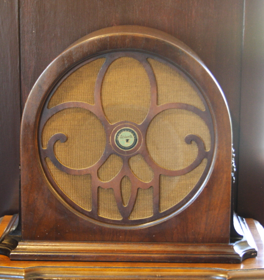 Mirico R3 by Midwest This little 3 tube radio is from around 1923. It works OK but is about as selective as a brick, which it is not much larger than. 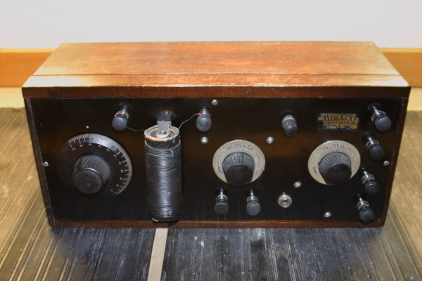 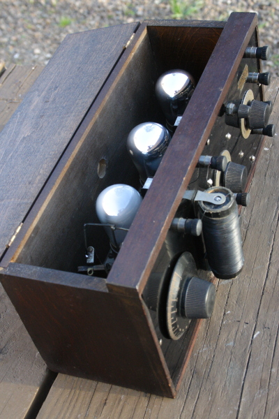 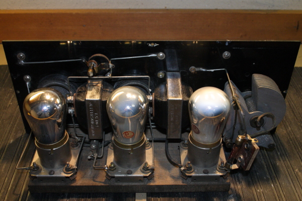 Halowat Model TR-5 from 1926 TRF radio built by the Portland firm Hallock and Watson Radio Corp. This is the one that brought me to the auction. There were two of them. This one includes a station log on the lid and a real log on a separate piece of paper. 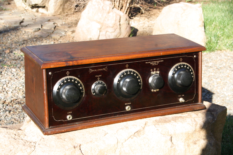 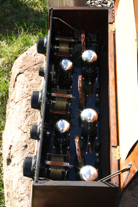 I just posted this comment on another site and thought I would post it here as well:
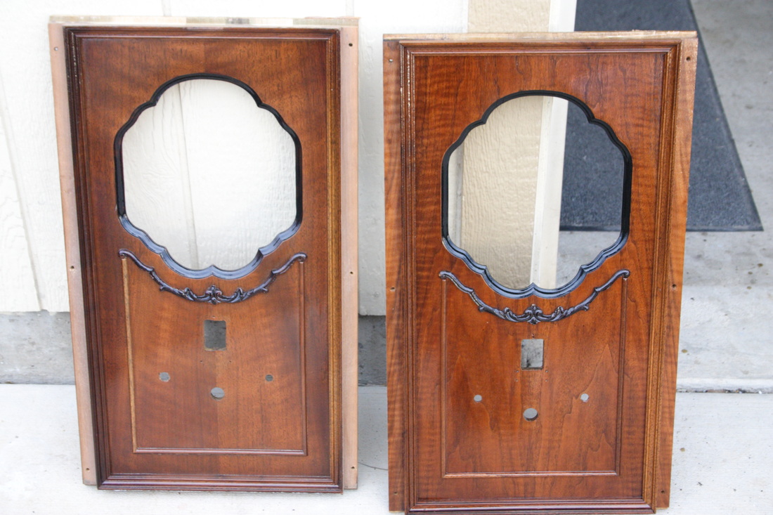
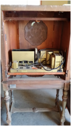
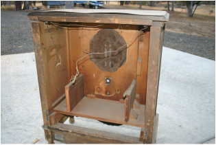
If a radio is restored so well that a plaque needs to be added to identify new parts then good job (you probably don't need a plaque) and the value to most people, collectors and the general public will be high, higher than the non-working radio with a rough finish and much higher than the same radio with broken or missing cabinet parts. Now, it all comes down to the quality of the restoration: Was the proper wood/veneer used - not wood filler or dark toner to cover the damaged edges (non original gradient shading)? Warping? Is the grain filled? Are there loose joints or loose veneer? Too much glue? Is the cabinet missing parts - like legs, escutcheons, knobs, Photofinish? Are there "over restored" items like the highly polished metal bezel? Are the colors of the cabinet correct, "white wood" (structural) should not be white. Get 1+ for using the factory correct method for "toning" the cabinet? Were the finishes used the closest available to the original. This includes the level of "gloss"? Have sharp edges been rounded by excessive sanding? Was the finish buffed out properly? Yes it is true that ALL wooden radio cabinets of the 1930s were not finished this way but most were. How well does the radio function? Are the controls noisy? How do they feel, too loose or binding? Is the dial glass, glass or plastic? Maybe not too important if it looks exactly original, but it can't have missing markings or wrong colors. This goes for dial scales as well. Are the light bulbs all there and functioning? Were original looking parts used on the top of the chassis? How about underneath? Get extra credit if the replacement parts exceed the ratings (better) than the originals, but still look like the originals, such as 630V caps in place of 450V. As a matter of fact this can be very important especially in filter caps considering our higher line voltages. A bucking transformer inside of the chassis is generally not a + so it goes with dropping resistors, but for some sets, those with resistive line cords being the best example, some adjustment must be made. The less obvious the better but it must be reliable and not burn the house down. Was the chassis painted if it originally was not or the wrong color or texture. And are painted components the correct color and gloss? Rust? Bad chrome? Was the plating polished off - See over restored. Is the correct hardware in place (do you see phillips head screws on a 30's radio)? Is the correct part number on the speaker and if it was re-coned, does the cone and surround look like the original? Does the interior of the cabinet including the back edge look original? Does it have the correct grill cloth? Does the radio have the correct type of tubes and tube shields ( G, ST, GT, Metal and so on)? +1 of it has the correct type of tubes and the correct brand and date codes. Is the wiring in good shape especially rubber insulated wire? Was the correct type and color of replacement wire used. solid core, stranded, cloth covered, rubber (is it obviously plastic?), push back and is the gauge correct? This might be the toughest question of the bunch and will result in a lot of "almost" answers. +1 if the wire is going to last for another 50 years - yeah this excludes (fail) even "good" original rubber insulated wire. Have the rubber mounting cushions been replaced with original looking ones including those on the tuning cap? This includes rubber cabinet feet. Are the knobs correct? Only 1/2 credit for plastic replacement for wooden knobs. (sorry knob makers). But new plastic for old plastic is Ok if the underside looks proper too and uses the correct grub screw. Is the plug and line cord in GREAT shape or a good original-looking replacement? Is the radio safe to operate? There are probably a few more and some people will argue (again) with the validity of some of these. But if you can check them all off, I would say that your radio has not diminished in value. 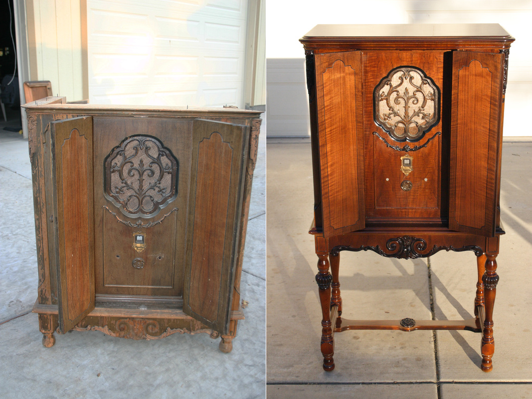 Seven or eight years ago we were strolling the pleasant streets of Jacksonville OR during the "All City Garage Sale". This was in the days when people came from all around and set up shop anywhere there was space, in the days before the city limited access and started charging a fee - back when it was more interesting. We walked along looking for, you guessed it, old radios. Spotted in the driveway, leaning against a post was this very short console. It had to lean since the parts were no longer held together by glue. The story was that this old radio came from a pile of old radios and parts that were the remnants of an old repair shop that had closed the same year that I was born and that was a while ago. It was told that the old fellow stored the radios in a barn, he passed away and later a tree fell on the barn. Some of the old gear was exposed to a lot of moisture and that is where the glue went. So, I offered $20 for the tubes in the flimsy, short cabinet. The seller said "OK", but I had to take the cabinet as well. We had driven the car to town. I might have gotten the radio to fit but decided to meet the fellow the next day at his home, besides, there were other items from the barn there too. The next day I spent $100 and loaded the back of my pickup full of cool old stuff and the various parts of the disintegrating Sparton radio. 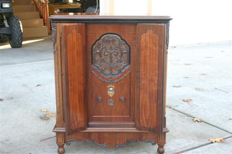 I could not resist fixing the radio and what was left of the cabinet. Then I just stored it away since it still had issues, like no legs. There was, even then, a mystery. I could find no examples of this radio even though it was listed in the Riders manuals. The serial number plaque was still there and it called the model a 620A. Now I knew that the chassis was the collectable but not too uncommon Sparton 410 Junior. The escutcheon even said "Sparton Junior". My search uncovered pictures of the cabinet belonging to a Sparton 620 NO "A". So what was the deal? 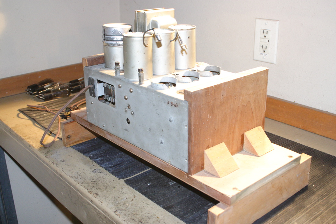 The chassis was still in nice shape and still retained its large "wet" filter cap combination. It did not take long to figure out that the cradle, pictured above, was factory built and even hosted the customary Sparton slide-in mounting system for the chassis. And so, time passed and passed and one day I saw what the radio needed, about 300 miles away. So off we went to pick up a non functioning but seemingly intact Sparton 620 (no "A"). Well somebody had worked on this 620. Known as an Equasonne, it was a large chassis - and heavy. It was missing a lot of parts including the big filter cap. It had also been raided for the speaker by the owners son who was probably wanting to acquire a big base "thumper" for his tunes. We all know how this always turns out and why replace a speaker that "doesn't work" (for him)? So the speaker was gone but I did not need it anyway and as it turns out, I did not even need the shelf that it mounted to.
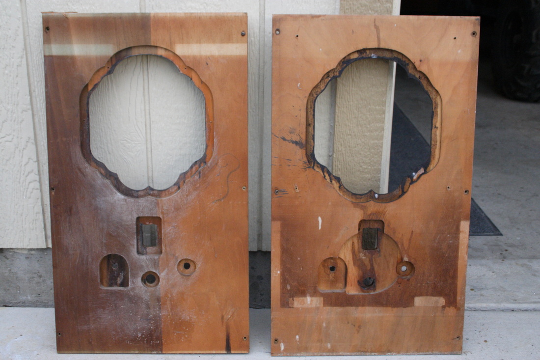
From the front of the cabinet the 620 and the 620A seem to be identical except for the missing 3rd knob and the associated decorative hole plug on the 620A. But inside the cabinet was another story and might require some history to explain. Note the round cut made to accommodate the Sparton Jr's. dial on the front panel, far right. The year was 1930. Sparton had been manufacturing the Equasonne radios and their own line of tubes to try to avoid paying RCA patent royalties. None the less, the two companies were in court. Sparton had the resources to challenge RCA where most smaller companies didn't. Yet they were likely to loose any claim regarding tube design in court and their Equasonne receiver worked but was no match for a good TRF let alone a super-heterodyne. They had reached an agreement with RCA which would bring to an end both the Equasonne and the now rare and expensive Sparton/Cardon designed tubes. The Sparton Junior 410 was one of the first radios the company made following the agreement. It was a TRF (Tuned Radio Frequency) receiver. Though branded Sparton, the tubes it used were conventional RCA models except the 2 push-pull output tubes and these were Sparton 183/483s which were baisicly a 45 (UX-245) with a 5 volt filament. I believe this was done simply to use up remaining tube stock at Sparton.
I am not sure which it was. Maybe Sparton had some of the 620 cabinets left or maybe they just wanted to offer a TRF radio in a console rather than the cumbersome 10 tube Equasonne. In any case it appears that the 620 cabinets were modified to accept the smaller 6 tube radio. Besides manufacturing the cradle for the smaller chassis and routing out the circular hole for the dial they had to take the top off the cabinet off to remove the upper 1/2 shelf that the earlier radio's speaker mounted to. This was not all that difficult. the top comes off with a few taps of a rubber mallet. A little wiggling and the shelf comes out too. The front panel is held in with screws. I would think that they would have modified it at the same time. The original 620A's cabinet shows the scars created by the removal of the shelf. The new speaker screws to a baffle board that is in turn mounted to the front panel. It would not have fit at all if the shelf were left in place.   So here it is complete with a pair of the now rare Sparton 183/483 output triodes and it's 10 inch Rola speaker.
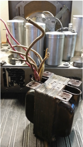
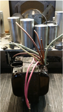
A few notes: Never confuse a Sparton/Cordon tube from this period with a similarly numbered RCA (or other brand) tube. A Sparton 483 is not the same tube as an 83 where as a 27 is a replacement for a 227. Making this mistake will cause bad things to happen! The original Rola speaker found in the 410 Junior was silver not brown. Unknown as to the color in this console. Has anyone seen another Sparton 620A? The radio still needs a set of Sparton 410 style knobs. Well, I have a couple of big projects coming up, but I'm not going to post about them until they are almost done. That way, if I mess them up, nobody will be the wiser . So, it looked like I had a little bit of spare time. If you work on old radios, you are always looking for parts. Sometimes you make due with what is on hand. Then that part you thought you would never find drops into your lap. BUT, you have moved on. Us electronics techs don't like "re-dos", so are generally uninspired to pull apart a perfectly fine, working radio just to put in an original part. So you make a note and put the part in a box and loose the box - somewhere. Well it was time to find about 6 - 8 years worth of little boxes, some of them not so little. The best start was an inventory. Pull out each radio, dust it (imagine that) test it, examine and in some cases test the tubes, then do an alignment. I had acquired a lot of date matching tubes that needed to replace "replacement" tubes - if that makes any sense. There were a lot of tube shields to be moved as well. At one point I actually had my RF generator radiating at full power to an antenna so I could align IF stages after tube or shield changes without bringing a console all the way down to the bench. Don't worry, we don't have any neighbors close enough to hear the "squeal". In the process I found 1 globe 80 that had gone to gas. LIT UP like a purple Christmas tree. Of course I was watching for this, so no damage. Found that both my Crosley Buddy Boy and Mate both had open windings in one of the RF transformers. One hundred and thirty ohms worth of #39 layered in 15 turns per layer, not to bad but the coil winder is not much good for 15 turns wrap, repeat. I just turned it by hand. Both are MUCH better radios now although a TRF like them will work with signal leaking past the dysfunctional stage. Then I got to one of my favorite radios, an AK 447, the big daddy of Atwater Kent table radios complete with a shadow meter and a shutter dial that moves vertically to switch bands. Only the shadow meter was not changing much with signal strength. Time for a through examination.  As you can see, when I acquired this radio at an auction the major concern was the damage done by the monkeys that must have been hired to move it. They had ripped off the top. The chassis was in pretty good shape, Sure, there was some cracking insulation on some of the rubber wire, but most of it was OK. Now this is why I advise people to change it all rather than doing part and leaving the rest. In the 7 or8 years since I had restuffed all of the original caps, the rest of the wire had gotten much worse. Regardless of what else was done a lot of wire needed to be changed. In addition, apparently at that time I was using plastic insulated wire. The stuff I use now looks and feels like the original, is rated for 600V and is REALLY hard to melt with your iron. So I might as well just do all the wire AGAIN. As found - in the museum:  Two days, and a crusty pile of wire later: 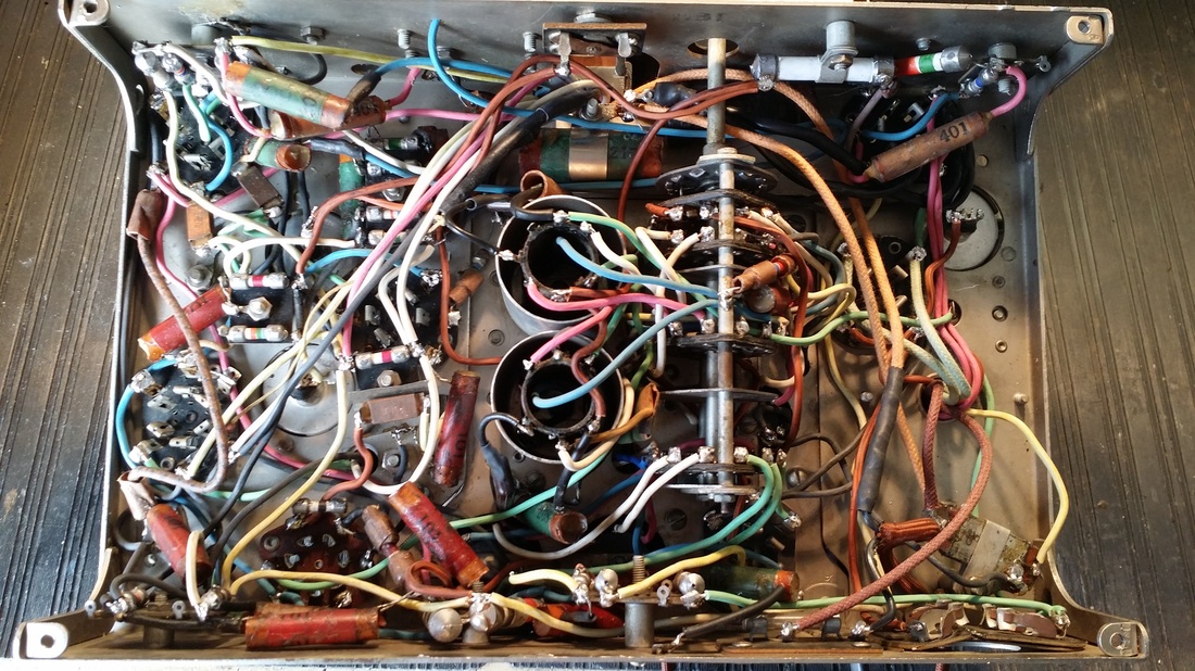 A couple of resistors had crept past the 20% error margin and needed to be rebuilt. Note the white one on the upper right. There is a grey band under the clamp. Looks a lot more original IMHO An alignment and one weak tube replacement later and the shadow meter works well. As does the rest of the radio. People often say that AK power transformers are weak. Well , I can say that most of them need to be rewired to avoid shorting rubber insulated leads.
And while you are at it, don't forget those IF transformers (and others). 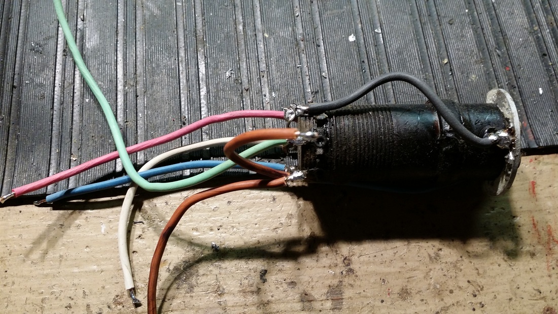 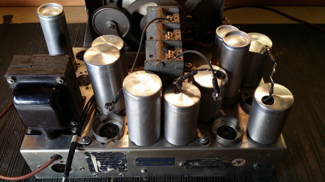 I think it should last now - at least until the next "inventory".
Pick your favorite: Kidney Stones Rubber Wire Taxes Tough Call! |
AuthorRuss Webb 
Russ Webb & Fuzzy
Best Buddy, Radio fixer Categories
All
Archives
December 2023
|
 RSS Feed