RUSS' OLD RADIOS
  • HOME
  • FOR SALE
    • CURRENTLY AVAILABLE
    • DO IT YOURSELF SPECIALS
    • EXCEPTIONAL DEALS
    • WITH MP3 PORTS
  • RESTORATION
  • BLOG
  • BEFORE/AFTER
  • CONTACT US
  • UNIQUE RADIOS
  • 1920'S Superheterodyne

1926 Neutrowound

9/4/2017

18 Comments

 
Sorry it has been so long since I posted. Honestly, if the smoke from the forest fires was not so thick outside, right now, I would probably be on my way to the shop.

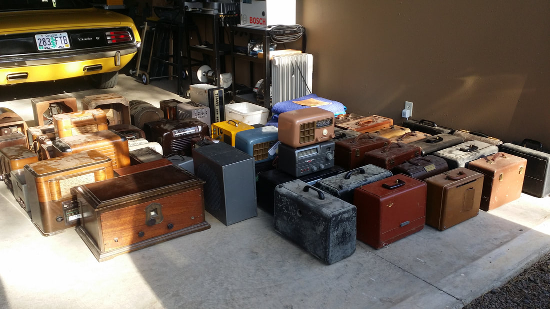
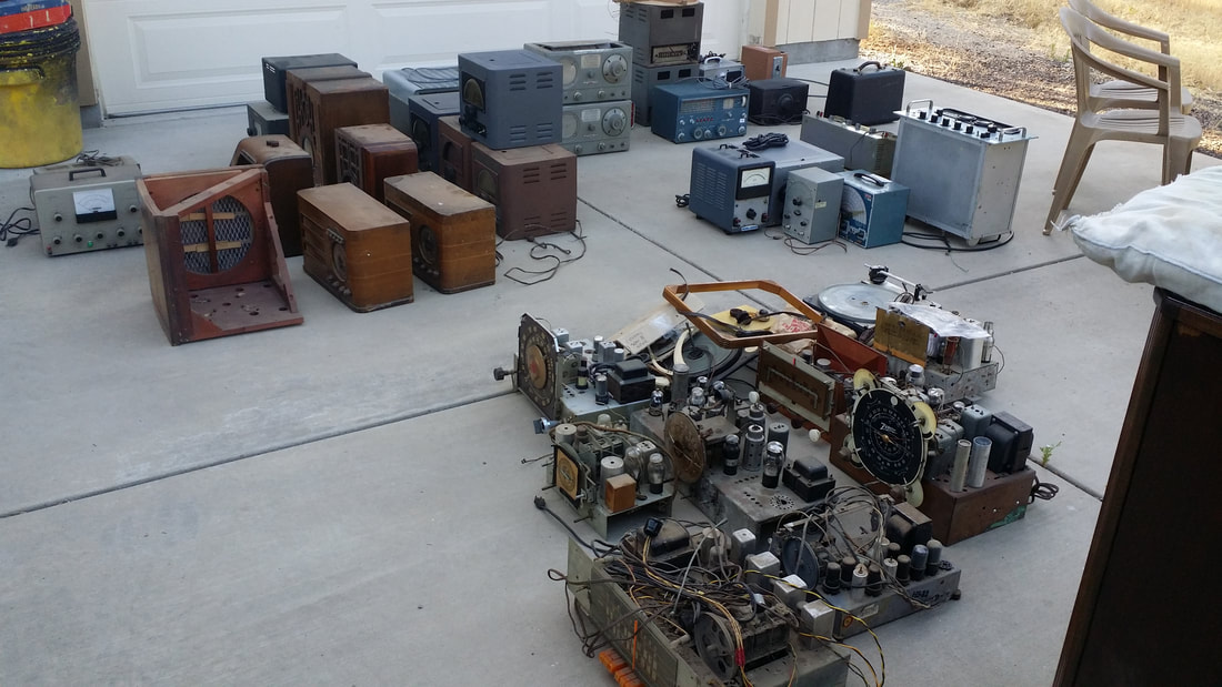
About two months ago we were given a large collection of radios, chassis and parts. This was such a nice thing to do. The collector had just retired. He had a lot of projects and travel planned and did not want to liquidate the collection by selling individual radios.

So after two truck/trailer loads, there were radios stacked in the shop and at both the front and back doors.
Picture
Picture
Well, I may be a radio collector (hoarder), but I am also unable to allow stuff to pile up for very long. So for the past two months I have been cleaning, restoring, donating, selling and disposing of this collection. But, that is not what this post is about. The rest of that story will be posted later.


THIS story is about the two 1926 Neutrowound receivers that I acquired in the meantime.


Picture
Picture
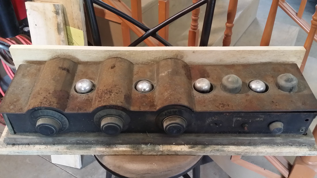
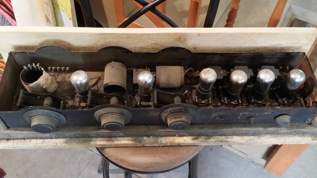
Of the two, the one pictured above, was by far in the worst condition. Even though it was well packed, it arrived soaking wet. That probably did not account for the rust and bug nests, but it didn't help either. BTW, none of those tubes were good either. All of them had open filaments.

I am in the process of saving the specimen above. The greatest challenge will be finding the missing tube shields/covers.

For the moment, we'll concentrate on the other unit, below.
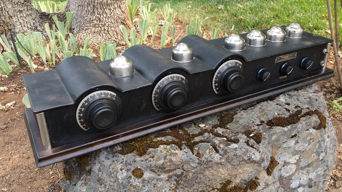
Picture
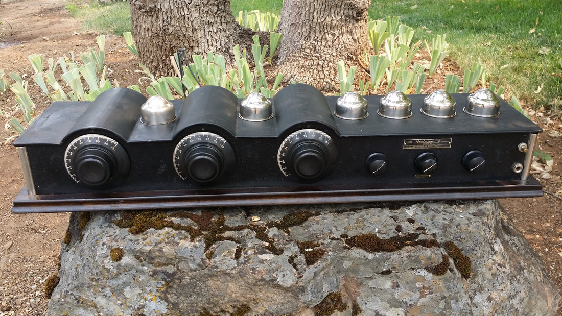
I won't take the time to illustrate the history of Neutrowound Radio Manuf. except to say that this division of Advanced Automotive Accessories only made radios for 4 or 5 years. This "Shielded Breadboard" design carried through those years with a few modifications.

Though this is a good radio, by 1926 the design was a bit dated. Then by 1928, the battery powered TRF was really behind the times. I can't really see why this design was popular in any of the years it was produced.

Pictures really don't express the size of this radio, measuring almost 3 feet long. It had 3 stages of tuning and the 3 dials rather than a single dial, as was becoming the standard of the time. I suppose that in a home that was yet to be "electrified" the need for batteries in 1927/28 was not a problem but elsewhere, the new AC powered radios were more desirable

.
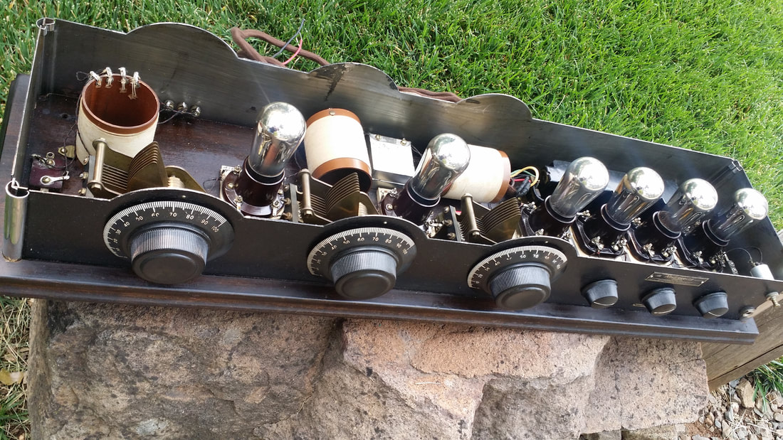
Picture
Radio construction on a "breadboard" was quickly becoming a thing of the past.

There are two significant and nearly universal challenges to restoring any of these radios. The first is RUST. A crinkle coat paint was applied to the outer metal surfaces. In the 1927 models this could be a striking blue or red. In all of the models, adhesion - at least in the long term, was not so good. This lead to a lot of rusted cabinets  (see top pictures). Coupled to that, it seems that in the finishing process, shellac was applied (smeared) to the inner surfaces of the metal. This hit or miss finish led to rust on the inner surfaces as well.

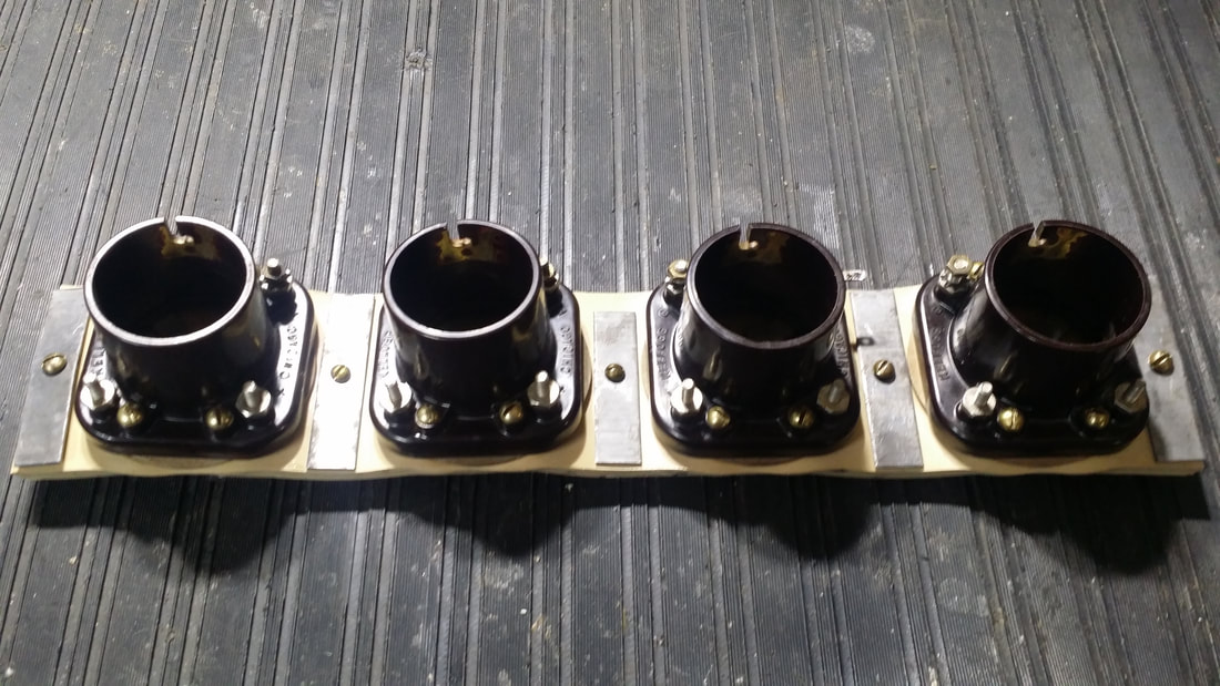
The second and probably most encompassing issue is caused by the degradation of the gum-rubber mounting of the Kellogg tube sockets.
Picture
The first two tubes have somewhat of a "hard" mounting since the screws pass through the socket flanges, through the 1/4 inch gum-rubber and into the breadboard. The last 4 tube socket are fully floating on the rubber strip shown above having been replaced.

I have not seen an example of this radio where the rubber has not become powdered or at least the consistency of a sugar cookie. Needles to say, the rubber should be replaced. Gum-rubber sheet is not a common hardware item anymore and the cost of a piece may be significant. Mounting the sockets on new rubber is not an easy task either.
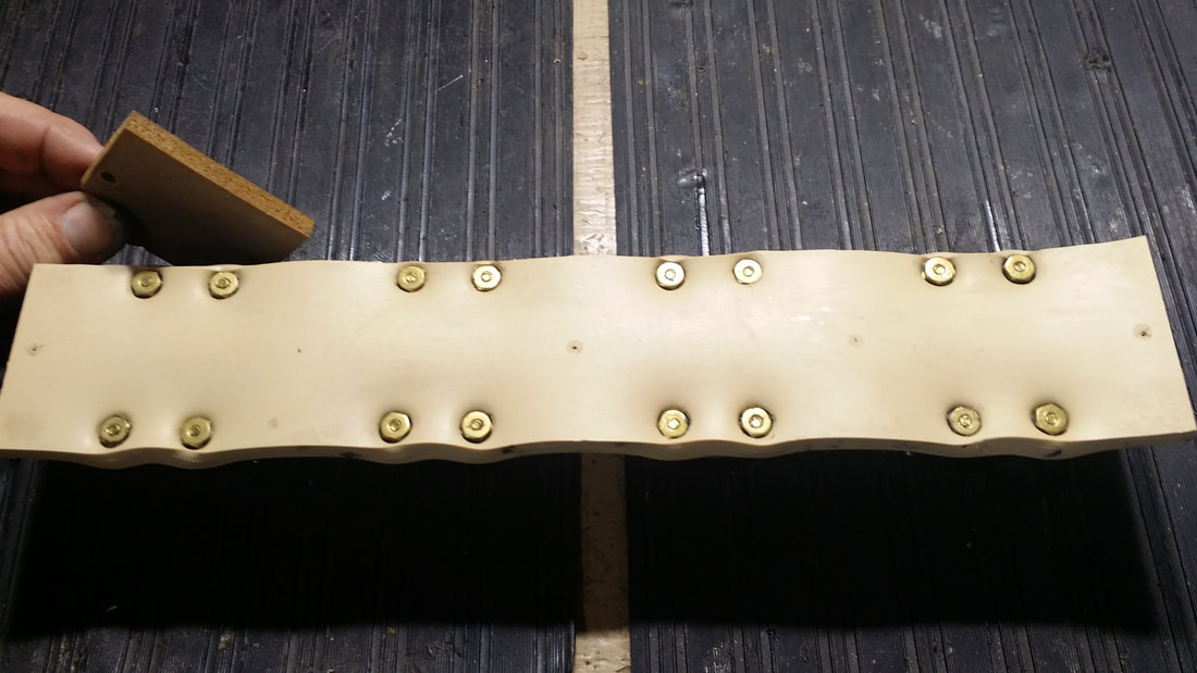
Picture
Above, I am holding an original piece of the rubber mount.

As you can see, mounting the sockets requires careful placement and compression of the rubber. This mount must compress the rubber without making a big hole in it, which would require starting over. I had to make a jig to hold the nuts/washers while compressing the assembly from the top. Otherwise, at least 3 (frustrated) hands would be required. By the time I made a few of these, the task was not so impossible, but at first it certainly seemed so.

Now consider what would happen if the sockets/tubes were not in the correct position.  You probably would not notice until you tried to replace the top cover and even more so as you tried to install the shields. In other words, incorrect placement results in the tubes hitting the top cover and/or the shields. The best you could hope for in this situation would be for the rubber base to give enough to allow the tube to fit through the hole at a slant - not acceptable.
Picture
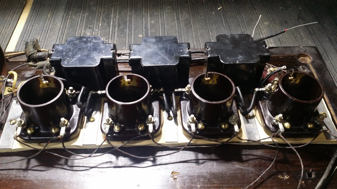
Other common issues include failure of the 3 interstage transformers pictured in back, above. And, the replacement of the two .5 uf paper capacitors. I restuffed/rebuilt all three of the interstage transformers and the metal-box capacitors for an original look.
Picture
I was able to save the original crinkle finish with just a little touch-up as well as the finish on the board. Not so lucky on the other radio, but, more on that one later -
18 Comments
Doug Faubion
11/26/2017 05:33:17 pm

I am in the process of restoring one of these radios and could use a schematic, do you know where I could get one. Thanks Doug

Reply
Russ
11/27/2017 12:45:52 pm

I had found one online and printed it, but now that resource seems to be gone. I probably still have the hard copy.

Here is one from ARF that was hand drawn:
http://www.antiqueradios.com/forums/download/file.php?id=113383

Good Luck

Russ

Reply
Doug Faubion
11/27/2017 05:13:34 pm

Thanks for the info for the Neutrowound, I think it will be a great help.

Doug Faubion
12/3/2017 01:58:16 pm

Do you know the voltages in this set, I am thinking +90 on the 171 tube and the two 01A's in audio amp stage, 45 V for two RF amps and 22.5 for the 01A detector stage, is that a good guess? Thanks Doug

Reply
Russ
12/3/2017 06:33:28 pm

If you are going to run a 171 for audio there is no real gain in running it at 90V. You might as well use a 01A. From that drawing above, it appears that all 3 audios have the same B+ connection but you could separate the last one and run it at a higher voltage.

One thing you should consider is the fact that this radio uses 3 stages of audio. It has a lot more gain than most TRF sets. This in it's self does not make it louder- but there is a lot of signal going into that last tube. I found that an O1A was loud enough.

I would suggest using a 112 for the last audio. Even at 90V they seem to have better tone quality than a 01A - in my opinion.

Reply
Doug Faubion
12/19/2017 05:33:12 pm

Thanks for the info a 112 it is. I have the audio section up and working. I am having trouble with the RF section. As per the drawing you sent me could you please tell me what voltage is on the yellow and Brown wires from the power supply, I can not get any RF to pass through the front end at all. Thanks Doug

Russ
12/21/2017 08:57:06 am

OK - I'm going from memory and this was about 30 radios back.

As I recall there are only 4 wires so there are only 2 for HV - brown and yellow. Yellow goes to the Audio, so about 90V and brown, around 45V.

Reply
Keith Waters
11/5/2018 09:16:51 pm

I am also in to restoration of a Neutrowound 1926. The tubes are not mounted on gum rubber but a solid piece of wood. Looks original to me.

Reply
Russ
11/8/2018 08:19:59 am

I assure you that it was originally mounted on gum rubber. Since replacement is very difficult, it is more likely that some one attempted a substitution.

Reply
Steve Pierce
12/6/2020 09:47:04 am

Hello. I just came by one these guys and am excited to get started. You mention using gum rubber for the mounts, I've found some reasonably priced material, but was wondering if silicone sheet might be a better option. if the new GR is no better than the original then it will become a 'sugar cookie" like the original. For all practical purposes silicone will last forever. Thoughts please. Thanks Steve

Reply
Russ
12/6/2020 12:05:01 pm

Steve,

For my restorations I use materials that are as close to original as possible, therefor, replacing the old cookie with a new one.

What ever you choose to use, what is critical is the position of the socket and the tube. If they are not in position on the X, Y and Z axis the top cover might not go back on – AND – even more likely, those rare, nickel plated tube covers will not fit.

Also the thickness (Z axis) makes a lot of difference to the mounting of the sockets. They must be fastened to the material by nuts and bolts that would seem to short for the stock thickness (1/4”). If it is thicker the hardware will not work. Even whit correct thickness, it is a real pain to get the sockets attached properly – making the proper location even less likely to obtain.

This really is the most significant challenge, unless you have to restore the finish.

Russ

Reply
Steve Pierce
12/9/2020 03:43:02 pm

.... so how did you replace the tubes exactly as they were. I'm thinking of building some sort of template. Also, do you have any idea on how to replicate the original crinkle finish. Thanks

tom
7/20/2021 03:15:56 am

hi all. i too have one of these rigs, and would like to repaint it. any tips or suggestions would be appreciated. shall i just clean off the surface rusting and "top coat" the existing wrinkle finish with satin black spray?
or light sandblasting and start over with new wrinkle finish?
anyone know what the original finish was? gloss?
thanks for any insight

Reply
Joe Pilbeam
5/6/2022 10:47:24 am

I have recently aquired a 1928 console neutrowound radiotrope with a phonograph and radio. It looks like it has two tube amps with four prong tube mounts.any info on this would be great, fascinating stuff, the cabinet is too notch craftsmanship.

Reply
maurice
10/30/2022 03:32:40 pm

good info. how about the C+ and C- connections..........

Reply
Russell Webb
10/31/2022 08:58:46 am

That would depend on the B+ voltage applied to the audio amp stage. Anything below 90V probably does not need a c bias.

Reply
Joe Pilbeam
10/30/2022 04:58:30 pm

I will take pictures of everything and send them to you. I want to modify one of the amps into a low output guitar amp, possibly?

Reply
Russell Webb
10/31/2022 09:02:24 am

This radio would be a very poor choice for that application. Just for one of the many reasons - Audio quality through an old high-impedance speaker (required) would be poor.

Reply


Leave a Reply.

    Author

                         Russ Webb

    Picture
    Russ Webb & Fuzzy

    Best Buddy, Radio fixer


    Categories

    All
    All
    Antiques
    Electronics
    Radios
    Repair
    Restoration
    Travels
    Vintage

    RSS Feed

    Archives

    March 2023
    November 2022
    October 2022
    July 2022
    January 2022
    December 2021
    September 2021
    June 2021
    April 2021
    February 2021
    January 2021
    November 2020
    July 2020
    June 2020
    April 2020
    March 2020
    December 2019
    October 2019
    May 2019
    April 2019
    March 2019
    February 2019
    January 2019
    December 2018
    November 2018
    October 2018
    September 2018
    June 2018
    April 2018
    March 2018
    February 2018
    January 2018
    December 2017
    November 2017
    September 2017
    June 2017
    May 2017
    April 2017
    February 2017
    December 2016
    November 2016
    October 2016
    September 2016
    August 2016
    July 2016
    June 2016
    May 2016
    April 2016
    March 2016
    February 2016
    January 2016
    December 2015
    November 2015
    August 2015
    June 2015
    May 2015
    April 2015
    March 2015
    February 2015
    January 2015
    December 2014
    November 2014
    October 2014
    September 2014
    August 2014
    July 2014
    June 2014
    May 2014
    April 2014
    March 2014
    February 2014
    January 2014
    December 2013

CUSTOM DESIGN BY SUE WEBB  06/2013       Redesigned by Russ Webb     Approved by Fuzzy   Updated:  Pretty much all the time, but I forget to change this date
Proudly powered by Weebly
Photos used under Creative Commons from valart2008, rafeejewell