
Spring cleaning time in the chassis/parts shed.
I have accumulated quite a few late 20s metal box radios. All of them are very common. These radios are so common that shipping one usually costs more than the purchase price. So why is that? Well, besides them being popular in the 20s and having been built like a metal brick, nearly all of them have little chance of ever working again.
I have accumulated quite a few late 20s metal box radios. All of them are very common. These radios are so common that shipping one usually costs more than the purchase price. So why is that? Well, besides them being popular in the 20s and having been built like a metal brick, nearly all of them have little chance of ever working again.
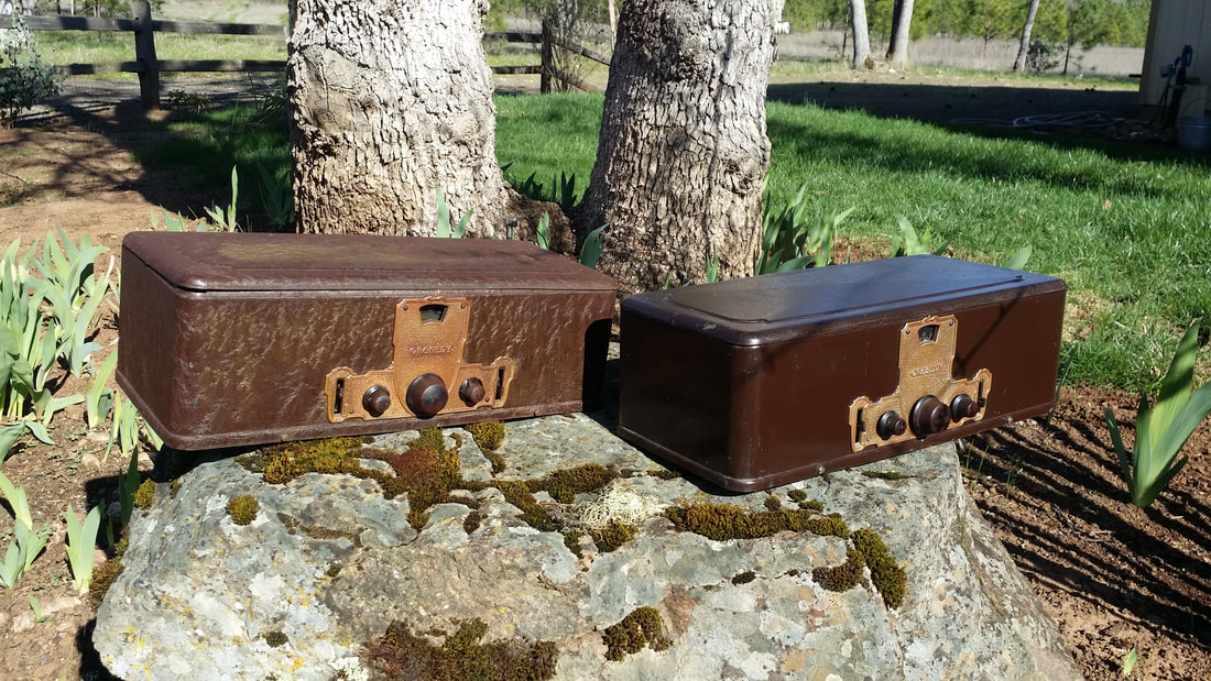
Above are a pair of Crosley Bandboxes. Along with many of the metal-box radios that Crosley built they suffer from almost universal pot-metal component failures. There are about a dozen cast parts that are critical to the radio's operation, so much so that a single failure will stop most restoration efforts.
I have salvaged a few of these unfortunate specimens, but realized that the spare parts were only good for other unrepairable models. So why bother keeping the parts?
I have salvaged a few of these unfortunate specimens, but realized that the spare parts were only good for other unrepairable models. So why bother keeping the parts?
The metal-box radio pile also had 4 AK 40s and a pair of AK 37s, also among the restoration challenged. These will be discussed at greater length below.
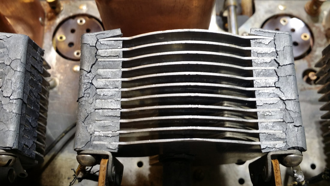
Above, the stator found in the Bandbox. This one has had it. The cracking/swelling pot-metal has caused the stator plates to contact the rotor plates. People have tried bending the plates so they don't touch but the linearity is lost in doing so especially since this is true for all 3 of the variable caps. The best that can be expected form such an effort is the ability to tune one or two stations with the rest of the tuning range, useless. Even if such a repair is quasi-successful, time will eventually lead to further expansion of the metal and failure.
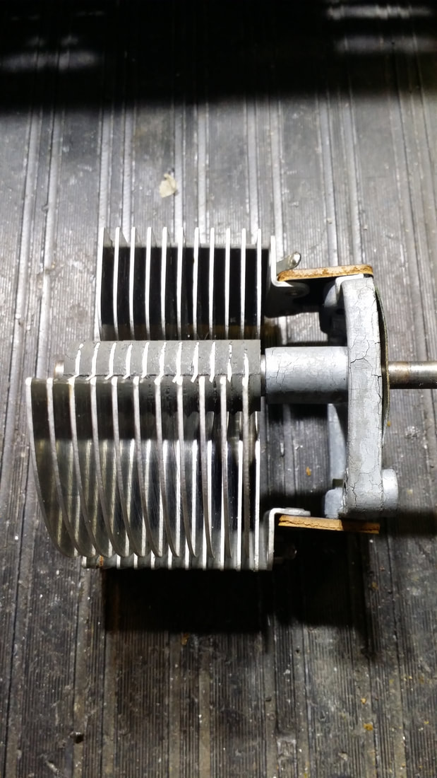
Below, the pot metal bracket, through which the rotor control shaft must pass, is also deformed and binding. Most of these look much worse than this one.
Below, the pot metal bracket, through which the rotor control shaft must pass, is also deformed and binding. Most of these look much worse than this one.
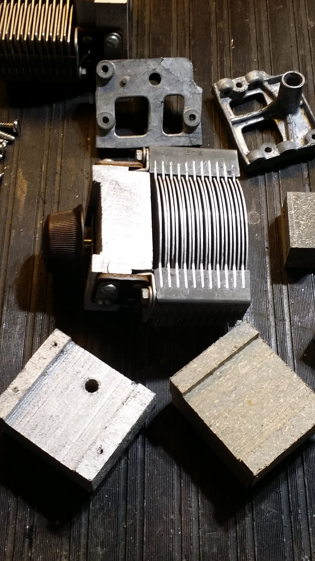
Below is a collection of these pot metal parts as well as the proposed solution. Note that the pot metal on this stator is in much better shape. Chances are good that one day this too shall degrade but I am going to use this one as is. The bracket(s) were not so fortunate.
At the bottom of the picture are 2 plastic replacement brackets and one has been installed in the assembly (center).
At the bottom of the picture are 2 plastic replacement brackets and one has been installed in the assembly (center).
While I was already on the path to design replacement parts, I had not settled on a method. I was moving towards recasting the components in resin when I found an old article showing the parts being made from old plastic decking. This article seems to be missing now, or I would post a link.
Since I had a pile of old deck material out on the "back 40" it seemed like a reasonable idea to give it a try. The old material that I had was an inch thick (newer material is only 3/4" thick and has a laminated wood-grain, not recommended). It is easy to shape on a table saw. It is easily strong enough and accepts wood screws, so the original machine screws/nuts will not be reused.
Since I had a pile of old deck material out on the "back 40" it seemed like a reasonable idea to give it a try. The old material that I had was an inch thick (newer material is only 3/4" thick and has a laminated wood-grain, not recommended). It is easy to shape on a table saw. It is easily strong enough and accepts wood screws, so the original machine screws/nuts will not be reused.
Now, from memory, the article mentioned above said that he had trouble with tracking/linearity and that is easily possible. Here are some notes to avoid that.
1. When cutting the brackets, shape the material in long strips. In other words shape the material by width and thickness, making all cuts possible prior to cutting it into equal length chunks. This will improve consistency.
2. The hole required for the rotor shaft must be drilled on a drill-press. It must be accurate and STRAIT! Do not make it over-sized, just adequate for the shaft to be pressed through the hole. Note that the hole is off-center.
3. A ground must be soldered to each of the copper retaining clips shown above.
4 Make sure that each of the mounting screw locations is identical.
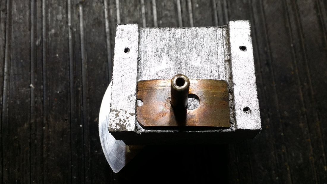
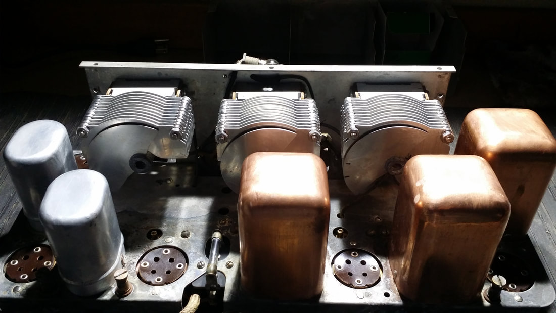
Above: This is the assembly that reused the original stators. Both of the pictures below show the unit in which I had to rebuild the stators using 3" #6 bolts and stainless washers. If you use larger hardware the rotor will impact the stator at the full closed position (or earlier).
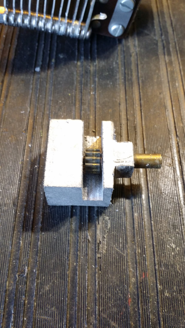
The original tuning drive gear bracket is also pot metal. I thought that this was going to be a challenge. Thanks to the ease of working with the plastic material, it was not. The shaft is pressed into the gear and will require a few gentle taps to remove and reinstall. I shaped the rounded nose (passes through the escutcheon) with my Dremmel tool.
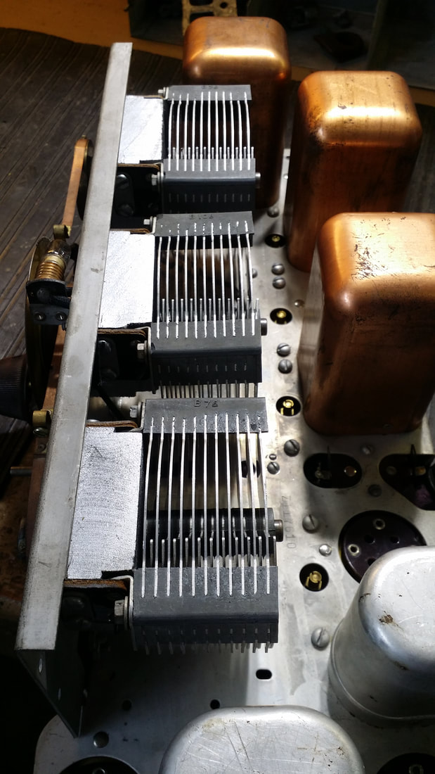
There are 3 more parts that must be addressed. And here is where the AK-40s come into the picture. The pulleys used on the Crosley were also made of pot metal as well as those used on the early AKs. Fortunately AK began to make them from brass at some point. So, below, you see that the outer 2 pullies have been replaced with brass AK parts. Note that the center pulley is the original with 3 screw hole used to mount the dial/gear. Great, right? No. Again tracking will be affected by this lash-up since that original part is slightly larger in circumference than the brass units.
The solution to the tracking issue is to drill mounting holes into the center brass AK pulley and use it as well. The holes will have to be tapped to use the original hardware. Luckily the original Crosley bands are adjustable enough to accommodate the slightly smaller pulleys.
The solution to the tracking issue is to drill mounting holes into the center brass AK pulley and use it as well. The holes will have to be tapped to use the original hardware. Luckily the original Crosley bands are adjustable enough to accommodate the slightly smaller pulleys.
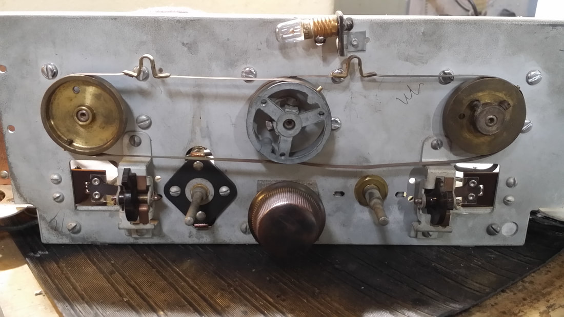
At this point I should note that the Crosley is a good candidate for this "mod" since it's original "one dial" construction incorporated 2 additional trimmers used to compensate for tracking errors in the original 3 tuning cap assembly. These trimmers/padders are the 2 levers located on the far lower right and left.
For some reason I found it easier to use these trimmers in association with the far right and left caps rather than the left and center as originally built. This only required moving one wire.
For some reason I found it easier to use these trimmers in association with the far right and left caps rather than the left and center as originally built. This only required moving one wire.
A couple of more notes on this radio.
Shields must be in place for alignment. There is a lot of gain in this radio. Stage coupling is an issue. Mine work best with low value grid leaks ~ 1m or even less. The first tube is mostly used to decouple the antenna/ broadband RF amp. You might find that the radio works just as well with this tube removed. Not suggesting that you do that, just an operational note. I found that on strong stations I was running the filaments well below 5V. It also works well with B+ at about 65V and audio final B+ at about 90V so you can lower your C voltages as well.
Shields must be in place for alignment. There is a lot of gain in this radio. Stage coupling is an issue. Mine work best with low value grid leaks ~ 1m or even less. The first tube is mostly used to decouple the antenna/ broadband RF amp. You might find that the radio works just as well with this tube removed. Not suggesting that you do that, just an operational note. I found that on strong stations I was running the filaments well below 5V. It also works well with B+ at about 65V and audio final B+ at about 90V so you can lower your C voltages as well.
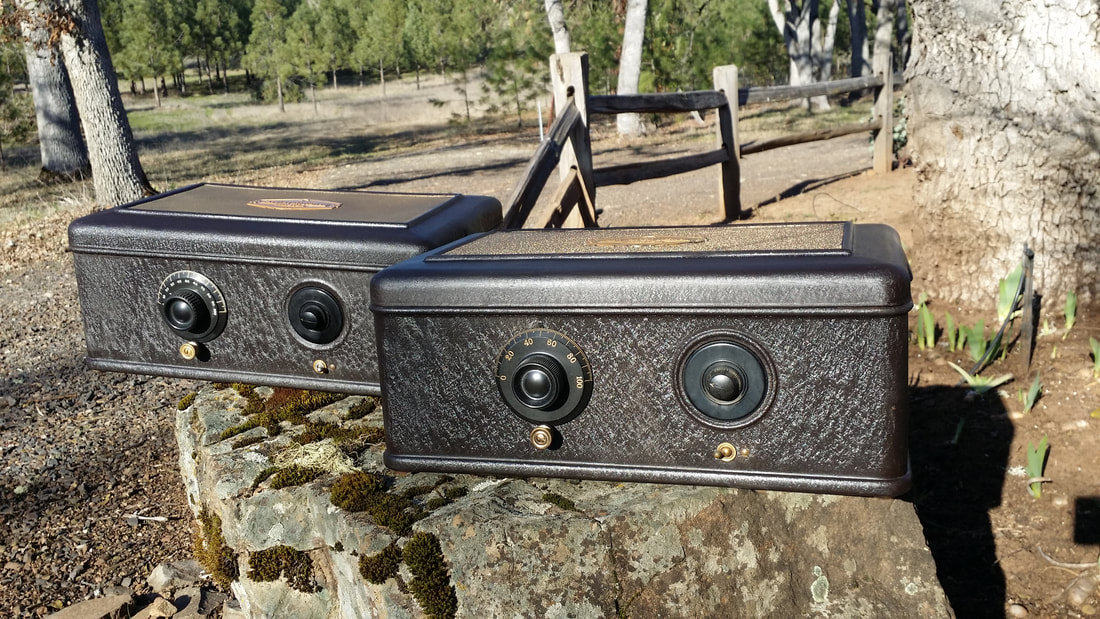
Now, About those AKs. You might ask why I borrowed parts from one to rebuild the Bandbox. After all the AK was probably a better radio. I think it also looks better. It is AC powered rather than running on batteries like the Bandbox. The early AK metal box radios also had pot metal pulleys, but that was not an issue here.
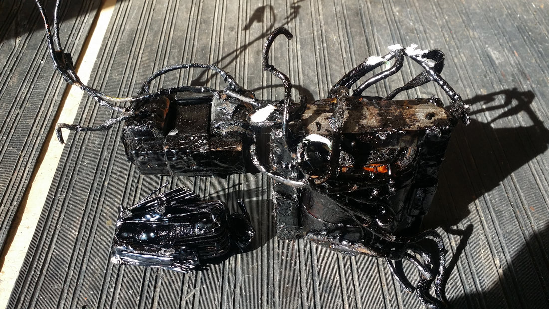
It seems that there is a radio-myth regarding the potted power supply that says that for some reason the filter caps are often good. This is just a fantasy. The effort needed to resolve this issue is beyond what most people want to invest in these rather common radios so it is easy to adopt this mistaken philosophy. The result is a radio with melted tar in the bottom and a failed power transformer - which leads to the second myth - AK power transformers are weak, which is also wrong. This, however, is a good way to end up with a parts chassis as was the case with several of the ones I had.
It seems that there is a radio-myth regarding the potted power supply that says that for some reason the filter caps are often good. This is just a fantasy. The effort needed to resolve this issue is beyond what most people want to invest in these rather common radios so it is easy to adopt this mistaken philosophy. The result is a radio with melted tar in the bottom and a failed power transformer - which leads to the second myth - AK power transformers are weak, which is also wrong. This, however, is a good way to end up with a parts chassis as was the case with several of the ones I had.
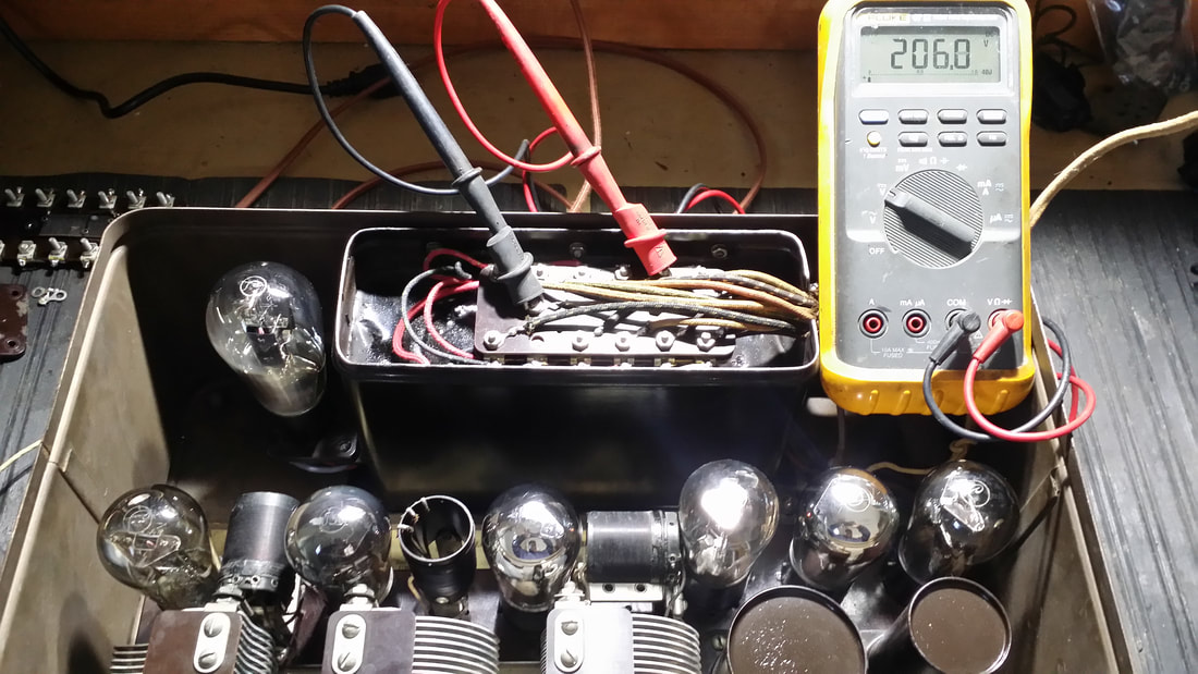
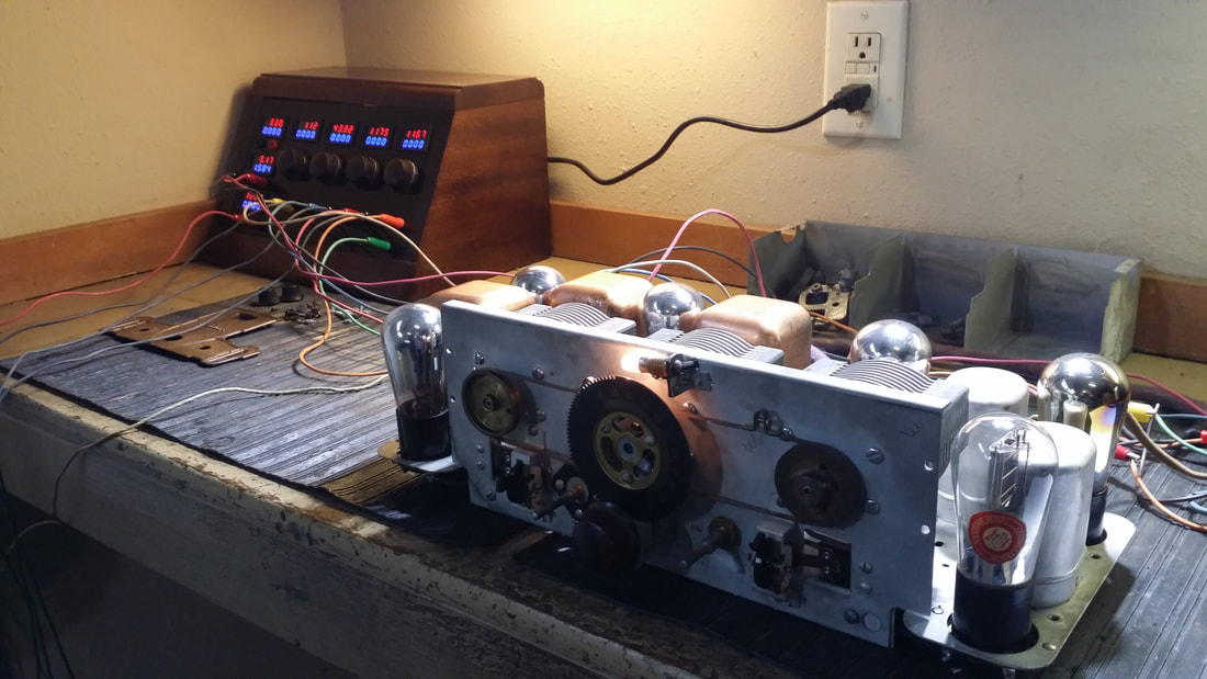
So, rather than hoping for the best, how can you judge the viability of one of these power supplies? As seen above a simple measurement is the best way to start. There should be more than 200V on the B+ when the radio is in operation. Much less and your radio is headed for the parts-bin. Even if the B+ is only a little less, say 180 - 190V this indicates excessive draw which is likely leakage in one or all of the filter caps.
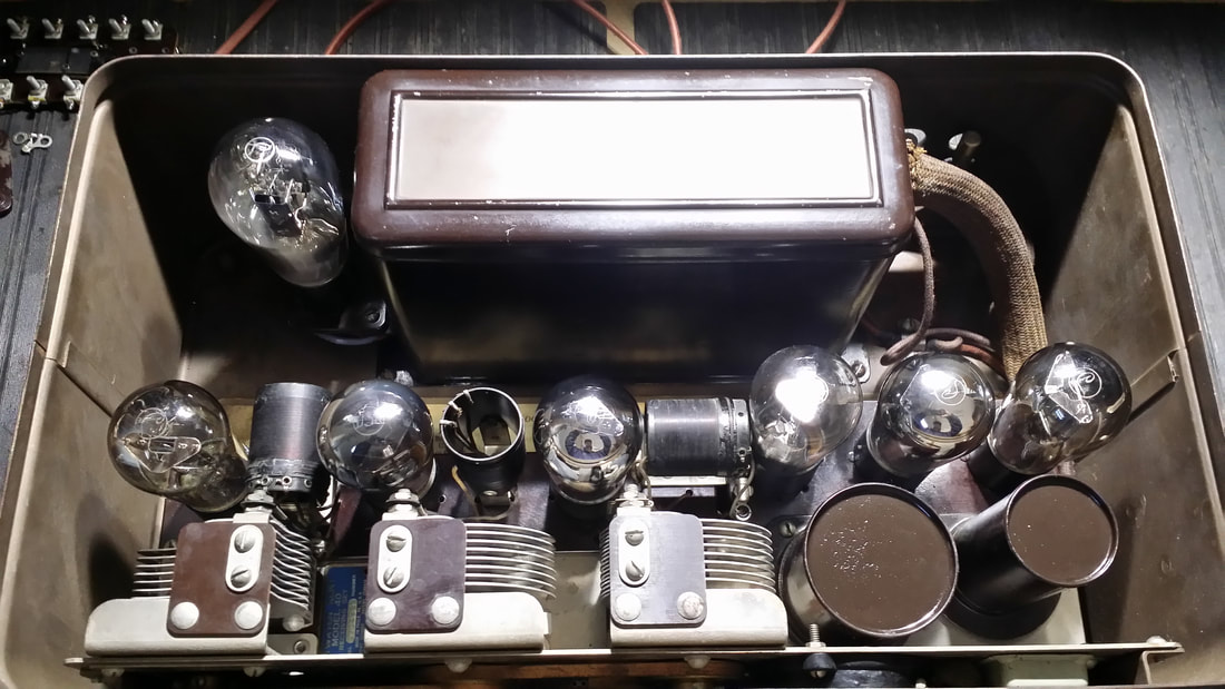
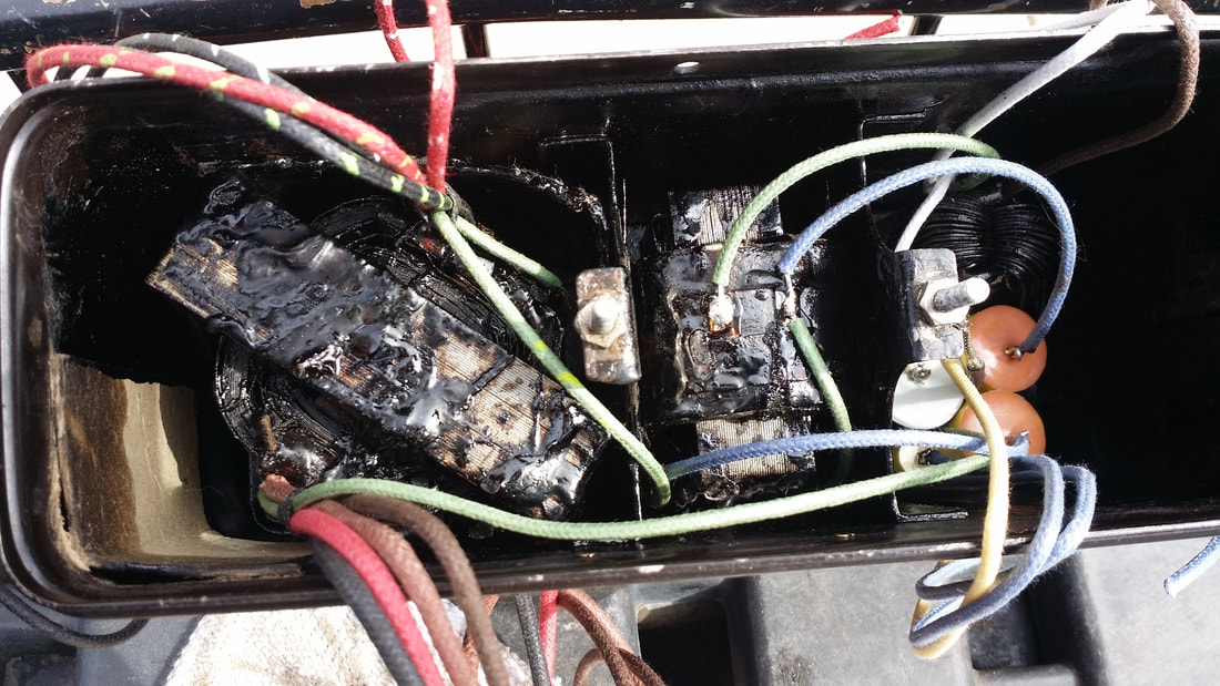
Below, you can see what is inside of the "can". The best way to service the filters is to gently warm the entire power supply can in an inverted position allowing the tar to run out into a metal container. Other methods usually result in damaged components. Only enough heat is required to melt the tar. This temperature is not high enough to damage the paint on the can.
Below, you can see what is inside of the "can". The best way to service the filters is to gently warm the entire power supply can in an inverted position allowing the tar to run out into a metal container. Other methods usually result in damaged components. Only enough heat is required to melt the tar. This temperature is not high enough to damage the paint on the can.
The added benefit of rebuilding the supply is the ability to replace the original wire which, by now has become brittle and unsafe.
Below you can see the components, rewired and repositioned in the can prior to replacing the tar. The 2 studs in the center are the ground. Sometimes it is best to bend these tabs upward to allow for easier passage of the components. It is always beneficial to remove the 2 nuts/bolts.
Another tip is to cut all of the wires as short as possible prior to melting out the tar. This is especially true of the wires leading to the rectifier socket. Also remove the cork found there.
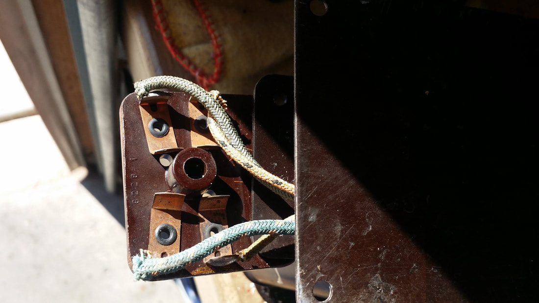
Below is the underside of the rectifier socket. Cut these wires as short as possible to prevent binding as the tar is removed.
 |  |
Don't forget to service the 2 glass-tube resistors on the B+ and detector B+ while you have the supply apart.
It is easy to forget about the bypass cap that goes between contacts 3 and 9 since it is the only one that does not have a leg going to ground (and is not one of the filters).
It is easy to forget about the bypass cap that goes between contacts 3 and 9 since it is the only one that does not have a leg going to ground (and is not one of the filters).
Above: repotted prior to reestablishing the connections on the power supply board.
Now, you will have to find parts for your Crosley elsewhere - - -

 RSS Feed