
THIS is, a Superheterodyne kit from Victory Products/ Victoreen.
As with most of the other 1920's superhet radio in the collection, this was a 'kit". Sold as a kit to try to avoid legal complications with RCA.
I am almost certain that this was constructed by the end user rather than a radio shop or other professional and the proof of that resides in the wiring error resulting in a missing meter. More on that below.
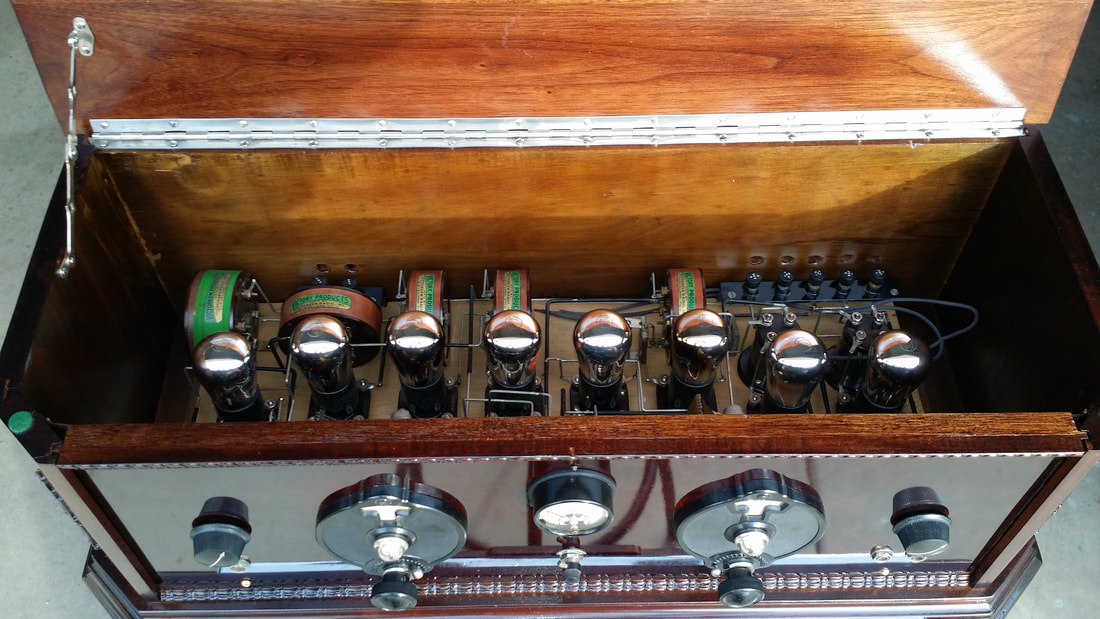
This is a rather typical early 20's 8-tube super which uses UX201As. It does have an antenna coil giving it some flexibility as compared to those designs that require a loop antenna, There is even a switch/jack that allows switching between a loop for improved directionality over a long-wire.
I am almost certain that this was constructed by the end user rather than a radio shop or other professional and the proof of that resides in the wiring error resulting in a missing meter. More on that below.
This is a rather typical early 20's 8-tube super which uses UX201As. It does have an antenna coil giving it some flexibility as compared to those designs that require a loop antenna, There is even a switch/jack that allows switching between a loop for improved directionality over a long-wire.
This was a stress-inducing purchase from Pay-Bay. The seller is a nice person. She tried to pack it well and maintain a reasonable shipping cost. But even on this short trip, the nature of these 20's cabinets allows a lot of movement of the chassis. The result was a broken cabinet.
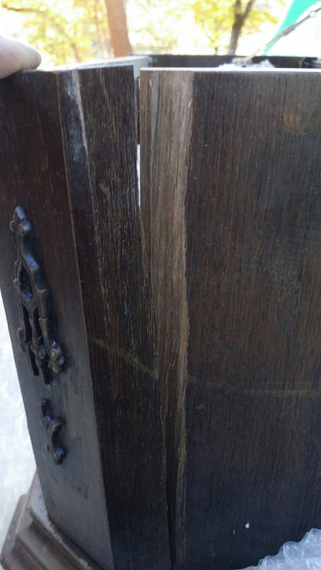
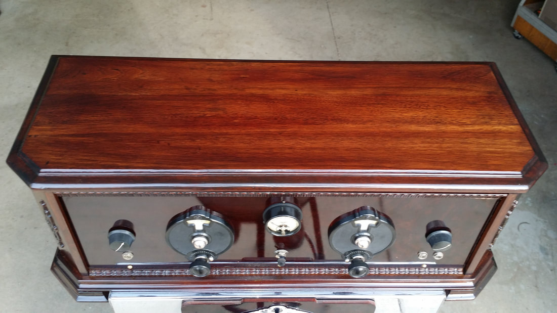
All of the cabinet was constructed from solid walnut, which sounds good, but a veneered plywood cabinet would probably broken at the seams rather than splitting the wood. There were split/broken pieces on both sides. Also, plywood is far less likely to warp.
Well, this did make one decision easier. The cabinet was going to have to be refinished caus' no amount of Go-Joe is going to rub out that split.
Well, this did make one decision easier. The cabinet was going to have to be refinished caus' no amount of Go-Joe is going to rub out that split.
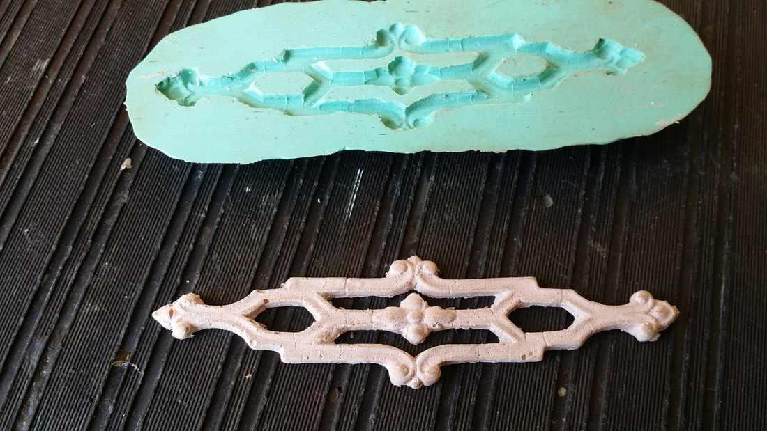
The decorative trim on the right was broken long ago. Having the trim intact on the other side made it easy to construct a mold and new trim was made (above)
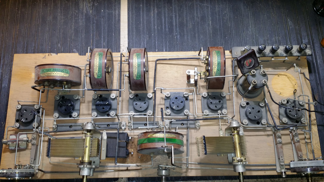
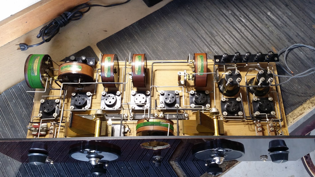
The rough ride broke loose several pieces of the square buss wire used in the original construction. The second audio interstage transformer had open windings, possibly because someone had tried to take it apart. Otherwise, all of the parts were here, less the already mentioned volt meter.
For the most part, the builder used high quality parts. Some probably came with the kit, others might have been purchased separately.
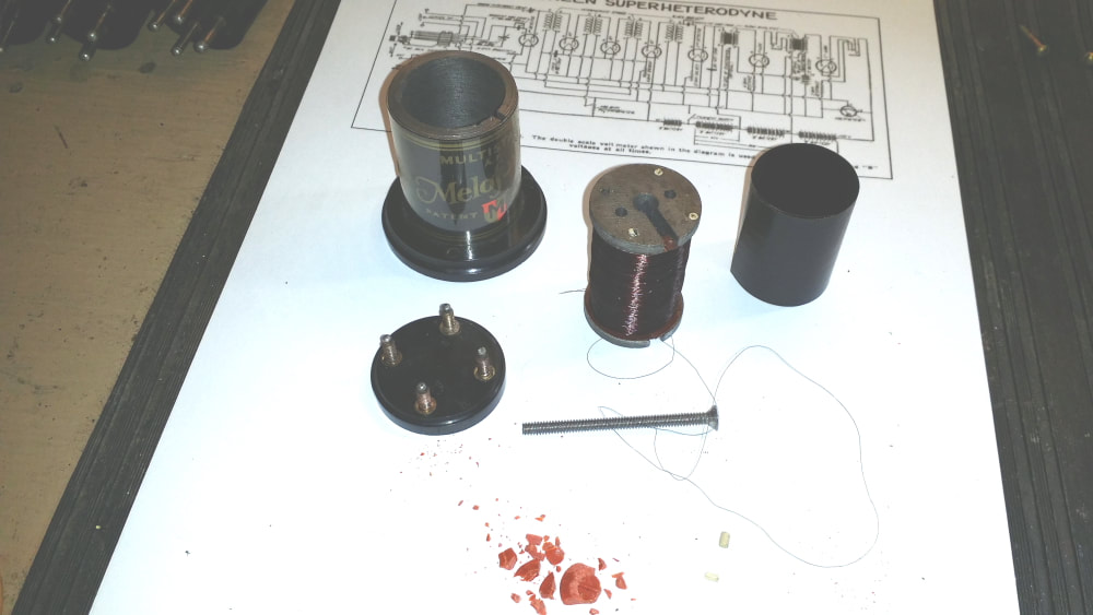
Above is the failed interstage trans. They were produced by a company I have never seen before and in a fashion that is very unusual for an audio transformer. The core was solid iron rather than the usual laminated stack. This solid core was shaped like a spool on which the primary and secondary were scramble/bulk wound. Then the spool was inserted into a iron pipe, held in place with the machine screw (above). Both windings were open so I just wound on enough #38 to fill the spool with a 3 to 1 ratio.
This transformer design is probably not the best for audio quality since the unlamented core is going to generate a lot of eddy currents. This might be the cause of some of the raspyness when using both audio stages in the video (below).
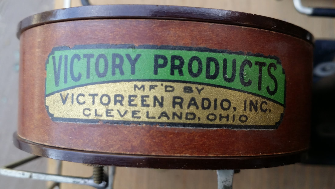
All of the Victory Products transformers were in good shape. This label would seem to indicate an early production date, possibly late 1924.
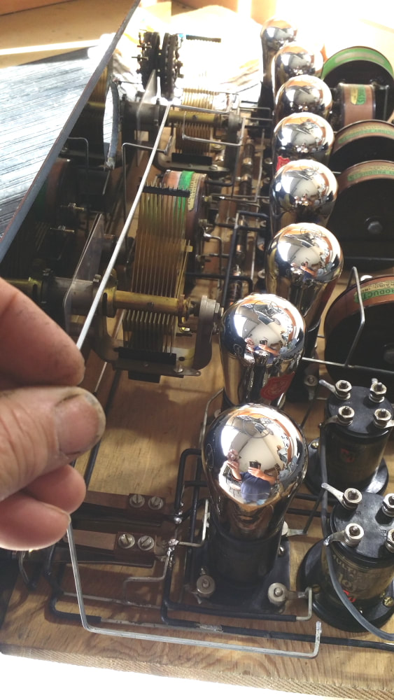
The original builder did a good job. The positioning of the transformer is slightly different than the later drawings and he used 5 of the 1A glass regulator/resistors rather than a 3rd and possibly , 4th rheostat for filament control. But in my testing the loss of these controls simply made tuning easier with no apparent downside.
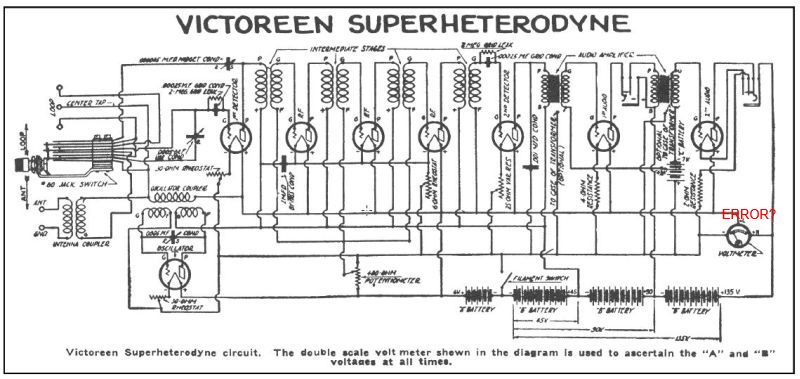
Unfortunately it appears that the builder was following a diagram similar to the one below, which is found on several locations on the net. I have made a mark near the volt meter (in red) to note the connection of B+ to the meter. (Above) is one of the buss wires that fell out when the radio was unpacked. As with the diagram it appears to run from B+ to the meter location resulting in 3 conductors/connections for the meter. Now, most meters only have 2 connections, + and -. And I can not recall a meter of this vintage that needed 100V DC for anything. I suspect that at some point high voltage damaged the original meter which is why it is missing. I used a meter from a Radiola to fill the holes for pictures but it is wrong.
Unfortunately it appears that the builder was following a diagram similar to the one below, which is found on several locations on the net. I have made a mark near the volt meter (in red) to note the connection of B+ to the meter. (Above) is one of the buss wires that fell out when the radio was unpacked. As with the diagram it appears to run from B+ to the meter location resulting in 3 conductors/connections for the meter. Now, most meters only have 2 connections, + and -. And I can not recall a meter of this vintage that needed 100V DC for anything. I suspect that at some point high voltage damaged the original meter which is why it is missing. I used a meter from a Radiola to fill the holes for pictures but it is wrong.
Cleaned up, rewired, resoldered, polished and repaired (below).
After checking the A circuit, I brought up the B+ and there was a station playing LOUD and clear (Faux Sports). I cant recall this ever happening before, at least SOME tuning had been required.
This radio has such good gain that the 2nd audio really isn't necessary AND it appears that the builder also knew this since he incorporated a slight mod to the last audio jack that turns the filament off when the 2nd audio (201A) is not used, saving some A battery life. To commemorate the builder, I left this mod in place.
Below is a video I shot just after powering the super up for the first time (for me). The meter would be reverse polarized with the original wiring so it is for looks - now. The fateful B+ conductor was omitted in the reconstruction.
The drawings for this radio in Rider's vol. 1 do not show the meter to have a B+ connection and are very useful to a person needing to do some reconstruction on one of these radios.
UPDATE: 12-5-2018
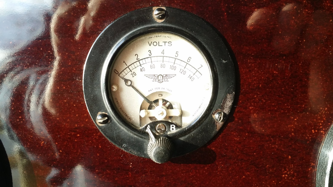
Duane had said that the meter might have been a switchable unit allowing the user to check/set both A+ and B+ voltages. I knew that such a meter would have to have had an integrated switch since there was no facility for an outboard switch on the front panel.
Harry was digging through a listing for a group of old meters and located the one pictured above. Not only does it work, but, this Jewel meter matches exactly the buss wire connection/position of the original construction. That makes it likely that this was the type of meter original used.
Thanks Harry!

 RSS Feed