RUSS' OLD RADIOS
  • HOME
  • FOR SALE
    • CURRENTLY AVAILABLE
    • DO IT YOURSELF SPECIALS
    • EXCEPTIONAL DEALS
    • WITH MP3 PORTS
  • RESTORATION
  • BLOG
  • BEFORE/AFTER
  • CONTACT US
  • UNIQUE RADIOS
  • 1920'S Superheterodyne

Old Radios and AI

3/31/2025

1 Comment

 
After all, AI, cell phones, computers and flat screen TVs can all trace their linage back to old radios.

I haven't added any radios to the collection lately. Instead, Harry talked me into revisiting the collection of radios that were donated several years back:

https://www.russoldradios.com/blog/radio-pile-results

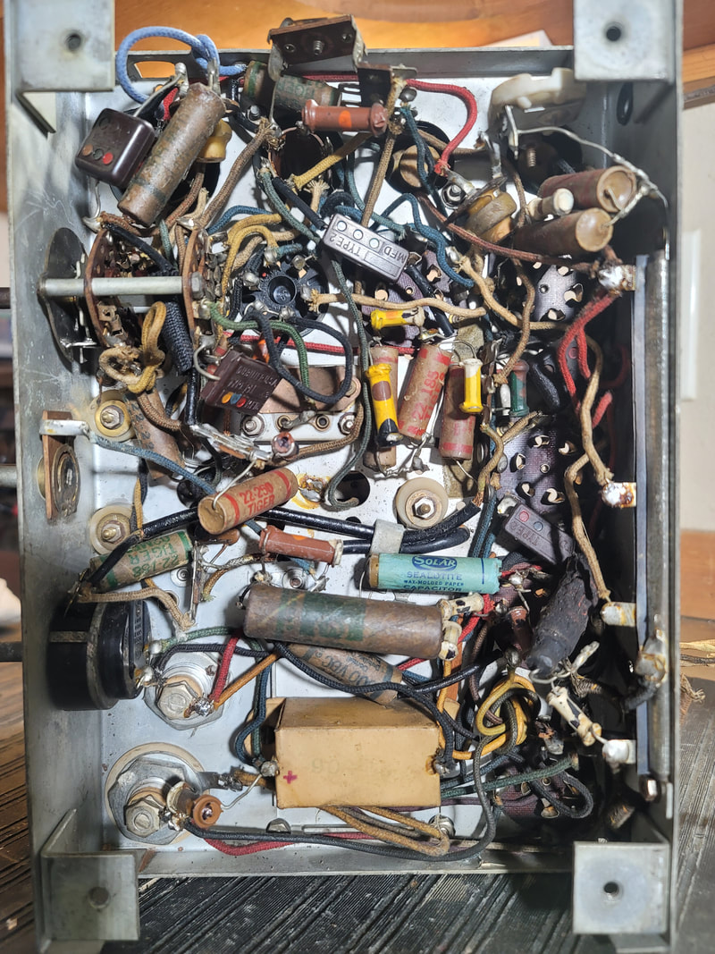
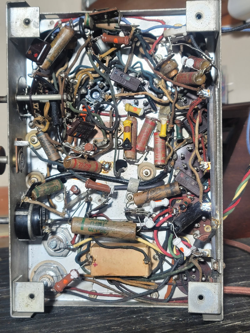
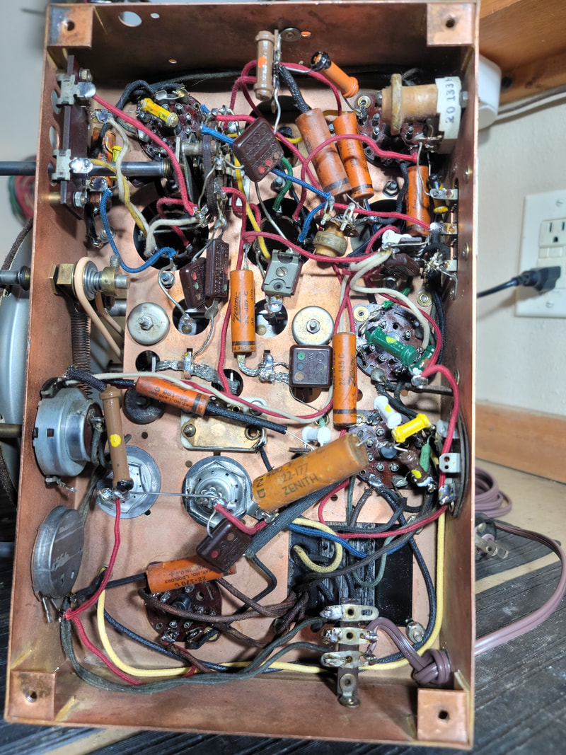
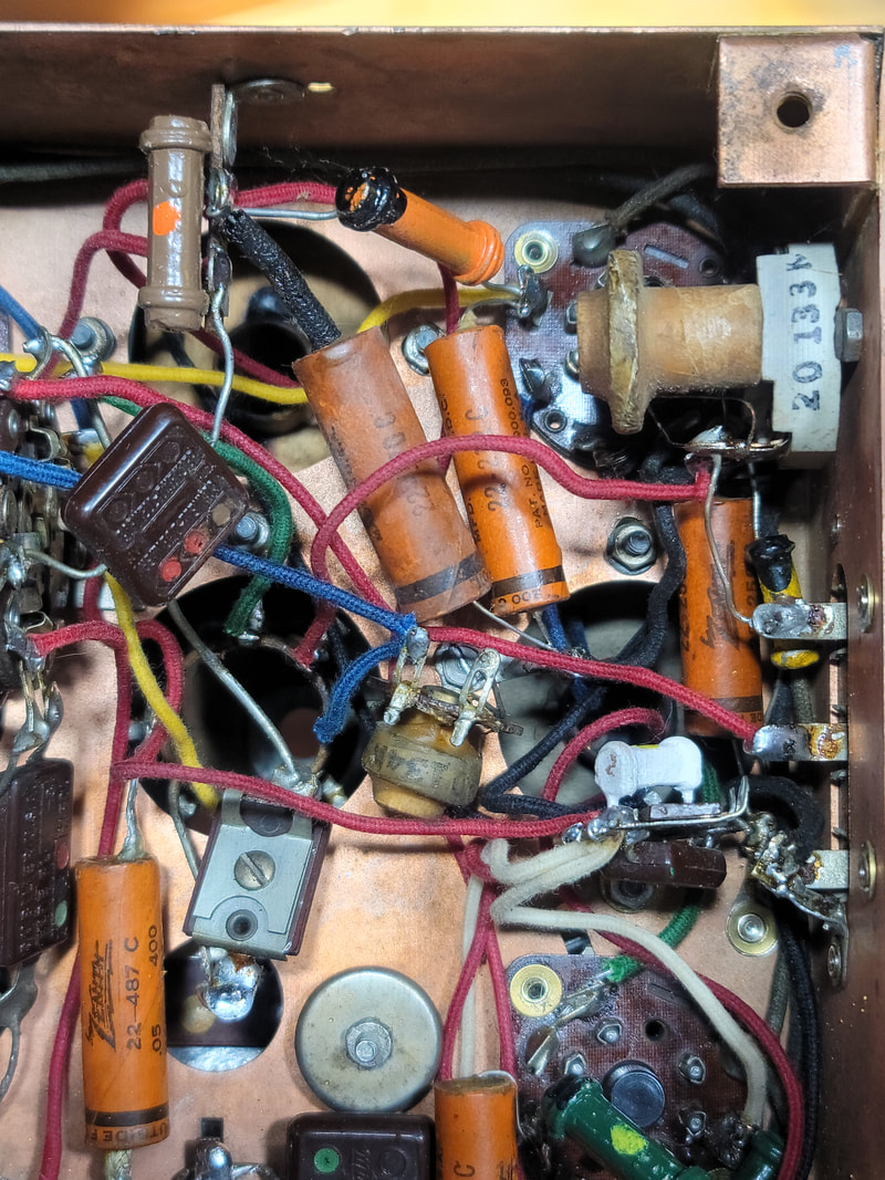
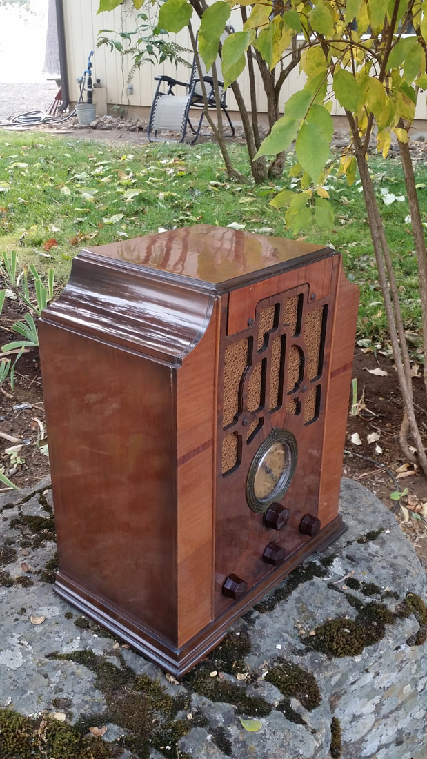
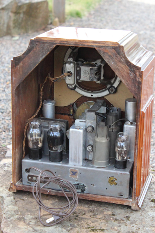
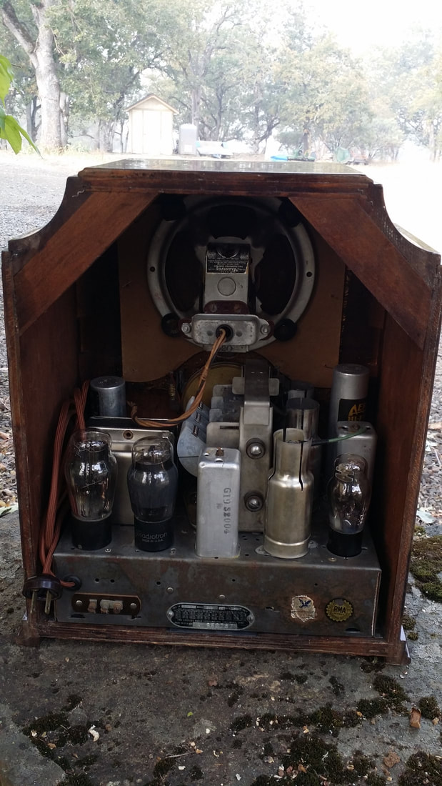
The focus of this collection was radios produced by the Crosley Radio Corp. Many were missing parts particularly the paper/foil capacitors. I had used what I had in stock and salvaged parts from a few chassis that were damaged or rusted beyond repair. But some of them still had modern yellow replacements showing beneath the chassis.

So we hunted for, and found, many of the missing parts. The capacitors were not labeled "Crosley" but did have the Crosley Part numbers, typically a W- followed by 5 digits, W-XXXXX.

While I was updating these I also replaced other non-factory parts.

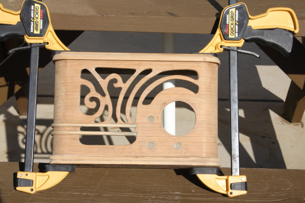
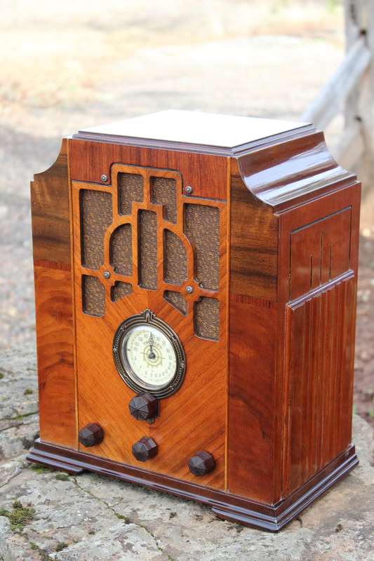
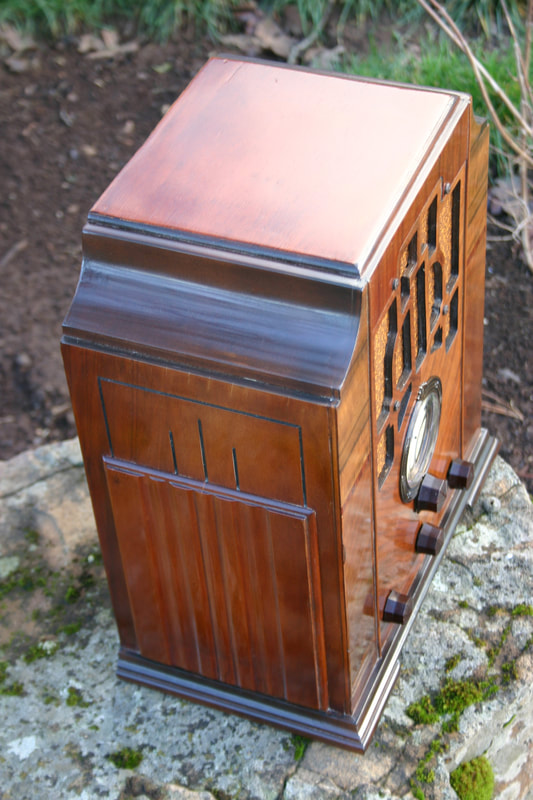
One radio, a model 61 with a 6H2 chassis has an unusual cabinet. It is the ONLY example of this cabinet variation that I have ever seen and was so noted in the post.


Picture
Cool, huh? But I was not working on this radio, rather a typical version BELOW:
Picture
Besides needing some caps upgraded, I noticed that it had a plastic insulated line cord. I could not remember what year Crosley stopped using cloth covered power cords. (Around 1935). So I googled "crosley 6h2 61 radio".

Now, I am accustomed to seeing pictures of radios in our collection when searching on Google and this was no exception. What I thought was interesting was the "AI" response pictured below.
Picture
Since AI was quoting me, I noticed the inconsistency right away. They had scraped a few lines from the blog post about the very unique cabinet and applied them to ALL model 61 radios. Specifically:

- "with some featuring decorative scroll work on the sides, which was later covered by a hardwood panel."

Actually, "some" was one and "later covered by a hardwood panel". seems to suggest that all of the model 61s were modified "later". None of this is correct, not even for the special cabinet.

Yes, AI is young - not quite ready to replace humanity. In the meantime, it should not be taken too literally.

Original post:

https://www.russoldradios.com/blog/favorite-crosley-and-a-mystery


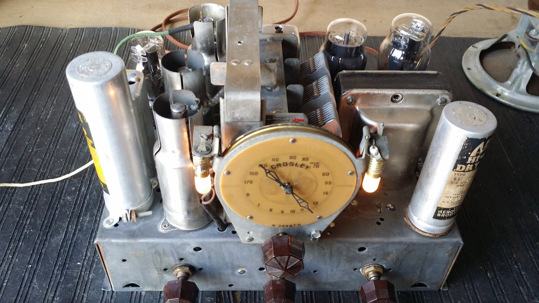
Here is a picture of the restored 6H2 chassis:
Picture
1 Comment

Emerson CS-272 from 1939/40

11/5/2024

0 Comments

 
In a weak moment, some months ago, I 'won" this on the auction site. No , no, not this, the one below. anyway. the cabinet was just funky. I have no idea what that finish was.

Emerson built a lot of inexpensive AC/DC radios in the late 30s and this is one of them. I suspect that they would be totally uninteresting to radio collectors if it were not for the Ingram cabinets. I have posted about Emerson/Ingram before. One of the best examples is the "Mae West" which has become quite valuable.

​There are several other blog posts on Emerson:
https://www.russoldradios.com/blog/emerson-from-1940
https://www.russoldradios.com/blog/i-havent-been-goofing-off-much

After restoration
Picture
"Before" - - yet after something. Below             Taken from the sale ad.
Picture
One of the biggest problems with restoring one of these Ingram cabinets is the loss of the "plastic' inlay that is most often red or purple(ish). It can be made but is a difficult task. Radios missing this trim are less valuable because of the difficulty associated with replacement of the inlay. See just below the cabinet top below.
Picture
The radio had been repaired in a manner similar to the refinish. There were  plenty of added terminal strips and the associated extra wire. The original wire was in bad shape. The speaker had been replaced with a permanent magnet type. A large choke had been mounted inside of the chassis to replace the missing field coil.

​This radio used GT and metal style tubes. They probably would have been branded "Emerson" or Arcturus.
Picture
I replated the top of the chassis because somebody had been polishing on it. You know, where the plating is polished off reveling the shiny steel chassis  - that will rust in short time.. OOO! SHINEY!.  BAD, don't do that. Besides you shouldn't be doing that to cadmium plating unless you have a way of dealing with the toxic dust. So, I just plated over it with zinc.
Picture
I was able to find most of the missing original components.  Three terminal strips were removed along with those replacement components and a lot of extra wire.. There were some pretty big puddles of solder where the replacement choke for the missing field coil had been attached. They were removed. Almost all of the wire was replaced by modern push-back and synthetic (rubber wire replacement). I found an Emerson speaker that matched all the specs but it is slightly smaller. If I ever find the correct one I'll swap it out.

​Russ


Mae West   Below
Picture
 - - - - I'm sure that you are just happy to see me.
0 Comments

Scott Phantom Deluxe 1940

11/4/2024

4 Comments

 
A family's special radio and its story:

I've had to slow down.
I can no longer spend much time leaning over the bench or driving long distances.  I still need to get things done around the tree farm. Hunting for radios on E-Pay or at "antique" stores has been off of my to-do list for a while now. I have completed several projects though. Each of them has been noteworthy. Here is the story of one of them.

​About 3 months ago I received an email. A Mr. D Arnold said that he had a Scott radio that had belonged to his grandparents. It had always occupied a spot of honor in their house and had worked recently. Unfortunately it had been demoted to serving in the garage. He asked if I knew anybody that could preserve it and keep it going.

My reply: "
Where are you? If I am close enough, I can help. If not maybe I can find somebody near by."
I get a lot of mail mostly asking for repair or what's my radio worth. I get a few like the one from Mr. Arnold but most of them are hundreds or thousands of miles away. Mr. Arnold replied "Bend".

Bend is a day-trip from here.

Picture
This is an "after" picture but it would have required a close inspection to see the defects "before". 

When I saw it, I was thinking Silvertone or Airline. Surely he must have been wrong about it being a Scott.
Picture
Nope! 

According to David Poland, Scott had acquired a few of these cabinets to be offered for free along with the purchase of one of their smaller radios - never a Phantom.

So, it must have replaced another radio in that cabinet? Also nope. From the mounting holes it was clear that this was the only radio ever installed in that cabinet. The instructions from Scott regarding installation in the Mayfair cabinet were with the original paperwork for the Phantom Deluxe which the Arnold family preserved.

​Here is the rest of the very unique story:
Picture
The phonograph is a Garrard AC-80 from around 1950 - a replacement.

Mrs. E.L. Arnold wanted to purchase a radio for her husband as a Christmas present. There were a few complications however. For one she was going to need a really good radio since their address was:

North Entrance Station
​Yellowstone National Park
Gardiner, Montana


Yes, according to Mr. Arnold, his grandmother was the first female ranger at any national park. Which points to the need for a good radio and to the fact that there were no radio retailers, or radio service nearby, not to mention radio stations.

How it was delivered or assembled is a mystery. Though, I suspect, that when it was delivered there was "some assembly required". Most of the components had been properly mounted but the receiver chassis itself required a block of wood to resist the force of gravity. Apparently the mounting brackets were not included (some things never change).
Picture
The chrome was in great shape.

Sept. 29th 1942, The Arnolds were having an unknown problem with the radio and had contacted Scott for repair. The response below also indicates that they would have liked to acquire a few spare tubes. Below is the response from Ms. E.M. Weishaar:
Picture
And I thought that we lived out in the bushes - - 

Picture
Can you imagine being given instructions to "fix it yourself" today?
I should also mention that later correspondence indicated that at the time of this letter Scott did not know who "Ben Arnold" was. His wife had made the purchase under her name. So Scott was making a good effort at customer service. (Scott needed the serial number). Most of the following correspondence was from H.C. Kerl at Scott.
Picture
Yeah, I still need a bigger bench.

Years later, April 4, 1944, Mrs. Arnold sent this letter to Scott. She indicates that the radio is "shot" and she is still looking for a new set of tubes but WWII was still happening. She also indicates that she is getting a lot of co-channel interference and asks about a replacement radio. This is the only letter from the Arnolds to Scott Laboratories that was preserved.

​
Picture
Still no tubes.

Can you imagine putting this thing in a box and getting it back to service in one piece? There were no freeways and few paved roads at the time.

​It probably would have gotten there just fine - - today - - yeah, sure.
Picture

A few parts, some caps and 1 resistor along with several of the controls had been replaced prior to my restoration. The work was neat but the values of the replacement controls were wrong, but not unworkable. Most of the caps had one leg cut and resoldered. An indication that someone had been looking for bad paper caps. Probably a long time ago since they were all bad now. 

This is the 'after" picture - below.
Picture
Capacitors restuffed and missing original parts replaced. Candohm voltage divider rebuilt. All cases of screws replacing rivets went back to rivets.

Scott was still confused as to who owned the Phantom or even which "Phantom" it was. Nice war-time stationary. At least , now, the letters were going to Wyoming.
Picture
Picture
Pretty wood. Toner has not been applied yet.

​

Picture
Mystery solved - or at least the "$64 question". That took a while. Interesting vacation/service proposal.

We don't know if the radio ever saw professional service. But there was one more letter - much later to Scott Radio Laboratories in Plymouth IN. It looks like the Arnolds and the Scott moved to Bozeman.
Picture
And, that was pretty close to the end of Scott Radio labs, though Mr. E.H. Scott had been gone from the company for a long time.

Meanwhile - - 
Picture
Yes, that is a hydraulic jack. This was previously the job of the 2 X 4 I mentioned earlier.
Picture
I cut 2 pieces of 10mm Baltic Birch plywood - good stuff. The radio chassis was attached to them with stainless hardware. The bottom of the chassis is attached to that 1" thick piece of hardwood visible at the bottom of the chassis. That is the 15" speaker. It could really use a tweeter.
Picture
I added the single tube preamp attached to the left wall. It can be jumpered out if you were to find a good crystal cartridge. It powers on and off with the phonograph .On the lower right is a Bluetooth receiver. The switch on the top right toggles them into the phono input on the radio chassis.
Picture
I wouldn't have picked that grill cloth but it appears to be original equipment so it can stay. 
​It is likely that this is the only Phantom Deluxe with this cabinet.

​Russ


4 Comments

I Haven't Been Goofing Off - Much

12/30/2023

1 Comment

 
Smile
Picture
Getting old. My time spent leaning over the work bench has become more limited. So I have to chose my projects more carefully, even when people try to give me "stuff to fix". 

​There is still the tree farm to take care of and with the weather changes, 117deg temperatures, drought and or, floods and fire prevention/control, there is still a lot to do. Quite a few large trees have died - free firewood, but that chain saw is getting heavy.

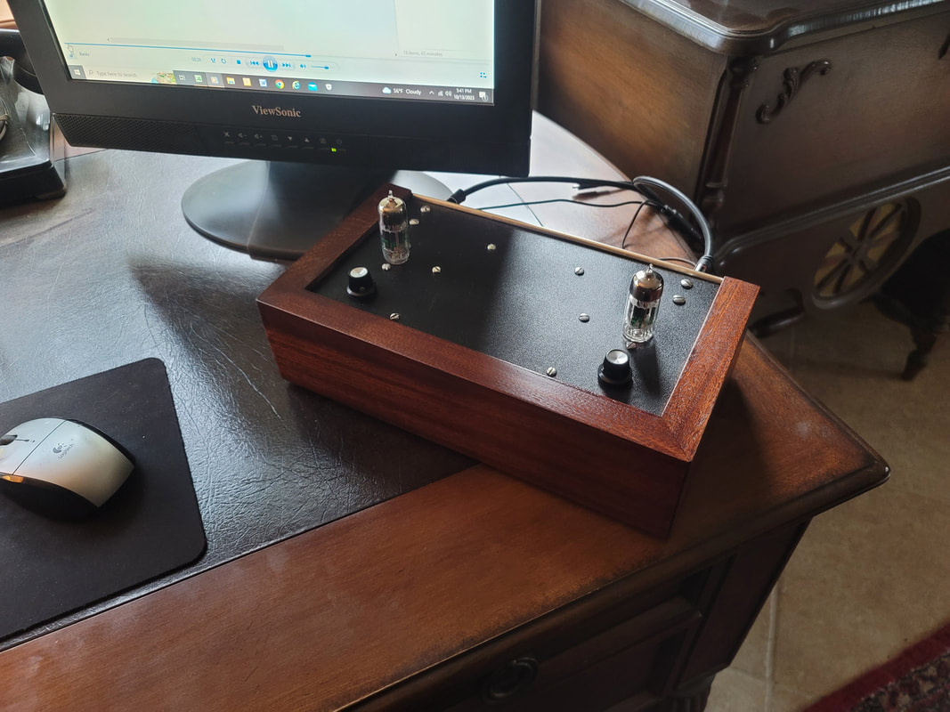
Below are pictures from projects, recently completed, for which I have not made posts. If you would like me to give further details about any of them , comment at the bottom. I might be able to go into further detail and pics. I highly recommend the OTL (output transformer-less) amp. It's performance is just amazing.


Picture
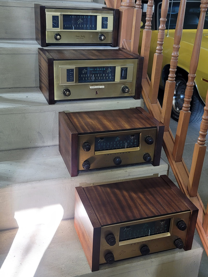
What to do with all of these nice Fisher tuner/preamps with no cabinets. Not enough room to equip the original consoles and the smaller/component cabinets are hard to find, expensive and kind of ugly (IMO).

So I set up a production line and made a few (8). The sides are solid 1" mahogany that I milled from raw planks, which I could get and could get at a reasonable price - just more work and a lot of chips. The tops are mahogany veneer on Baltic birch plywood and they will slide out the back so the radio can be serviced (tubes) without removing the cabinet.
Picture
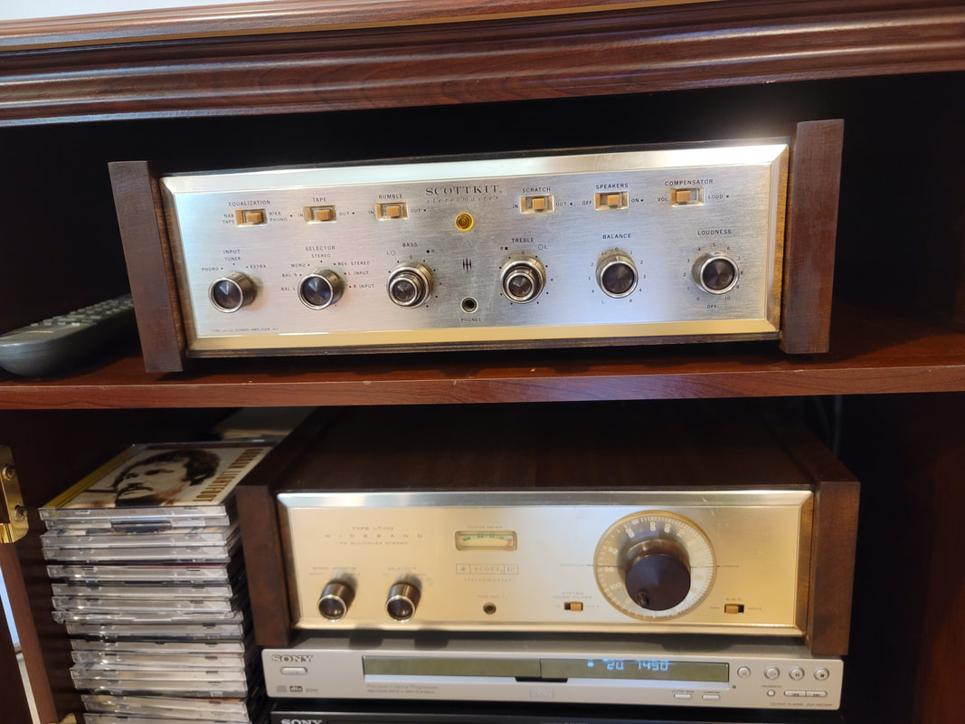
Scott amp and tuner, also in new matching cabinets
Picture
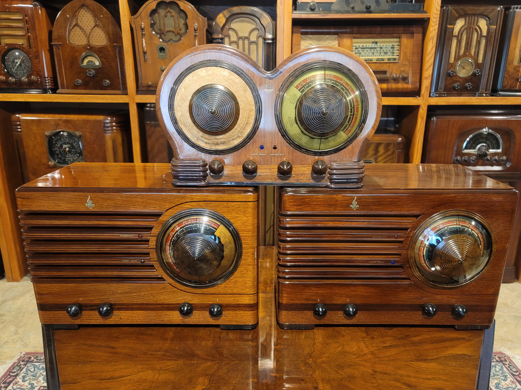
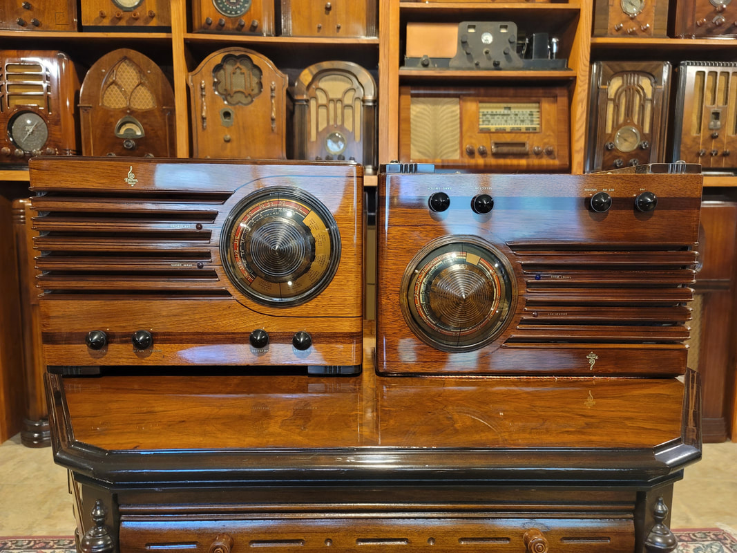
EMERSONS

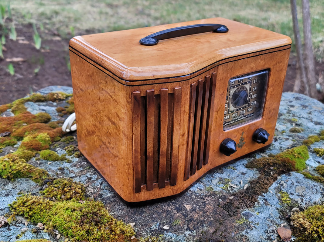
CV-295 Bird's eye maple cabinet
Picture
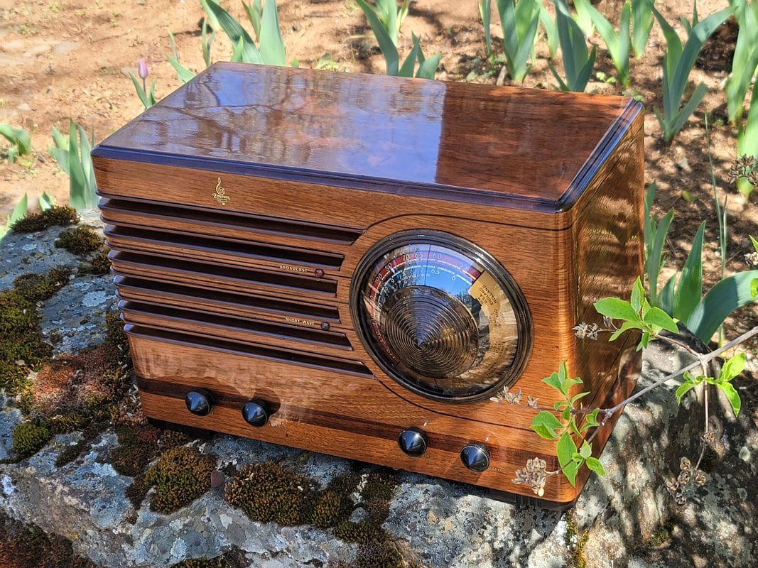
BW-231, sometimes known as "half of a Mae West".
Picture
Attempting to resolve imbalance.
Picture
Hum---
Picture
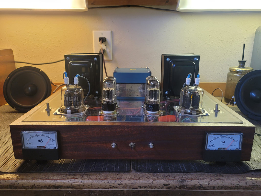
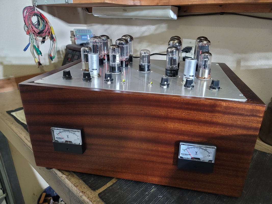
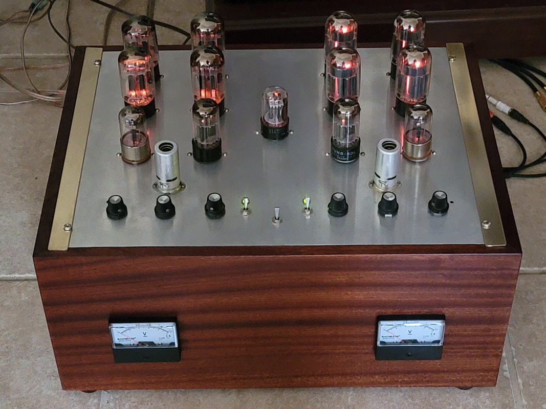
829B single ended stereo amp.

I had heard that these are not audio tubes.
Picture
Showing an idle current of about 90 ma. per channel. That is 45ma for each parallel pentode (2 per 829B). I later reduced the idle current to 60 ma @ 310V. It will run in either ultra linear or pentode mode.

Yes, it is built on a sheet of plastic. Very quiet - until you turn it up, with no hum from the regulated power supplies.
Picture
Somebody help me up - -

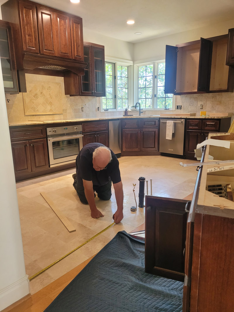
​New kitchen.
Picture
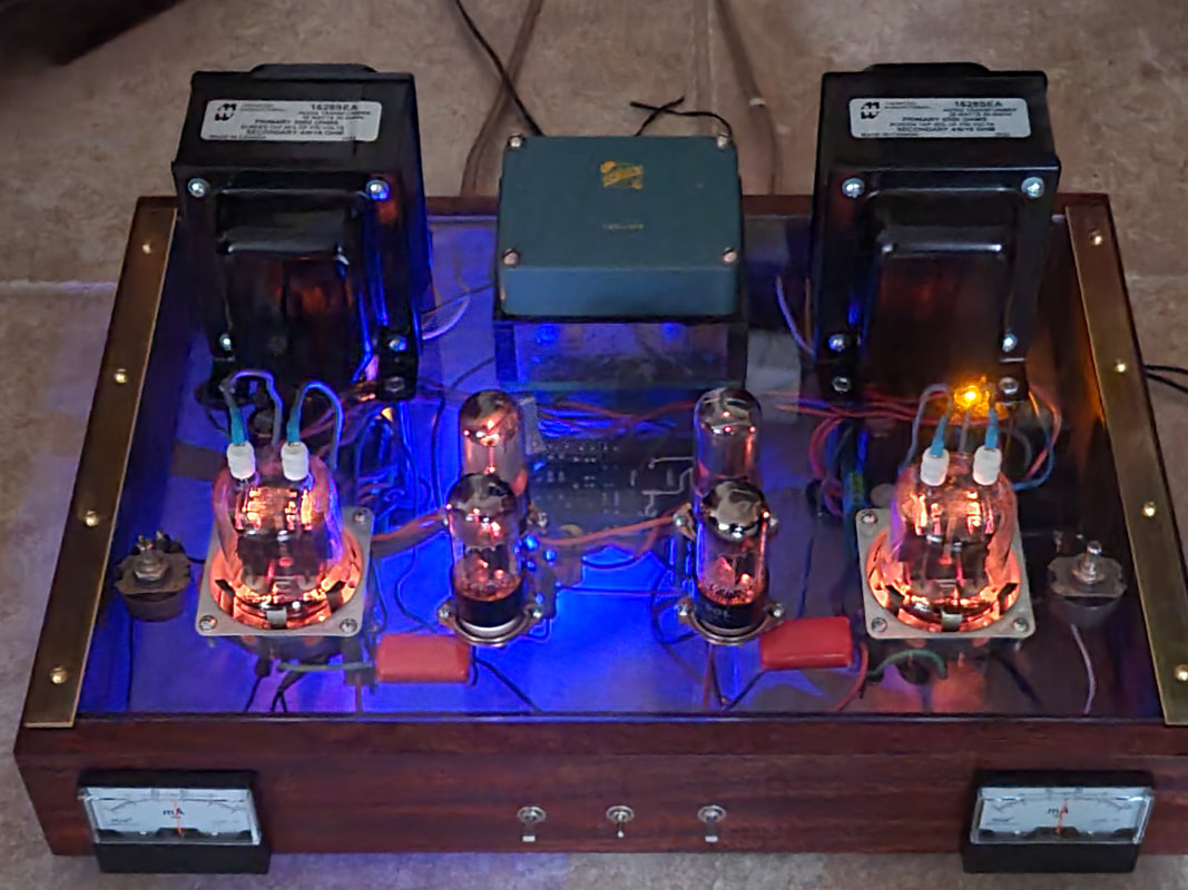
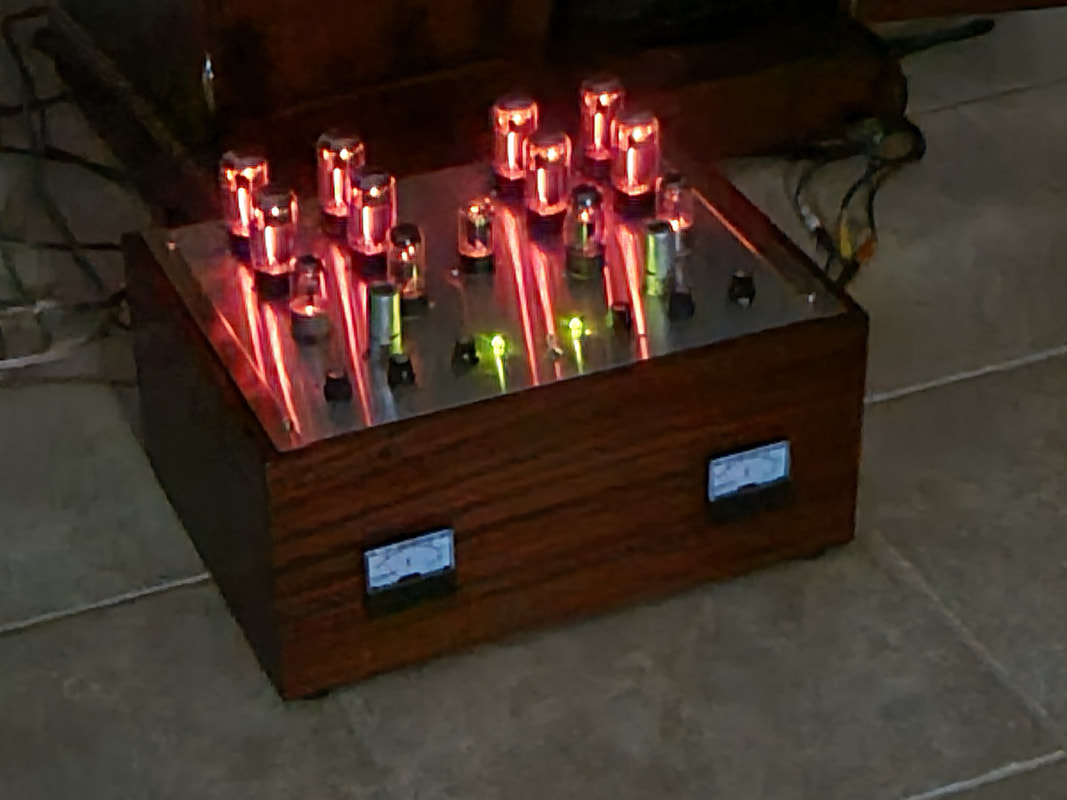
Now for something entirely different - OTL Circletron

When I went to school (EE. Rolla MO.), what I REALLY wanted to learn, was how to build my own amplifiers - well - and to get a job to pay for them. In the following 50 years, there was always something else to do. But I collected a lot of parts, like 6080 tubes (6AS7). A SUPER TRIODE, that is only used in power supplies (frowney face 😉). Yea, right!
Picture
Idling at 125 ma per 1/2 of 1 channel (total X 4). Total peak current through both channels, about 2A. at 160V.
Picture
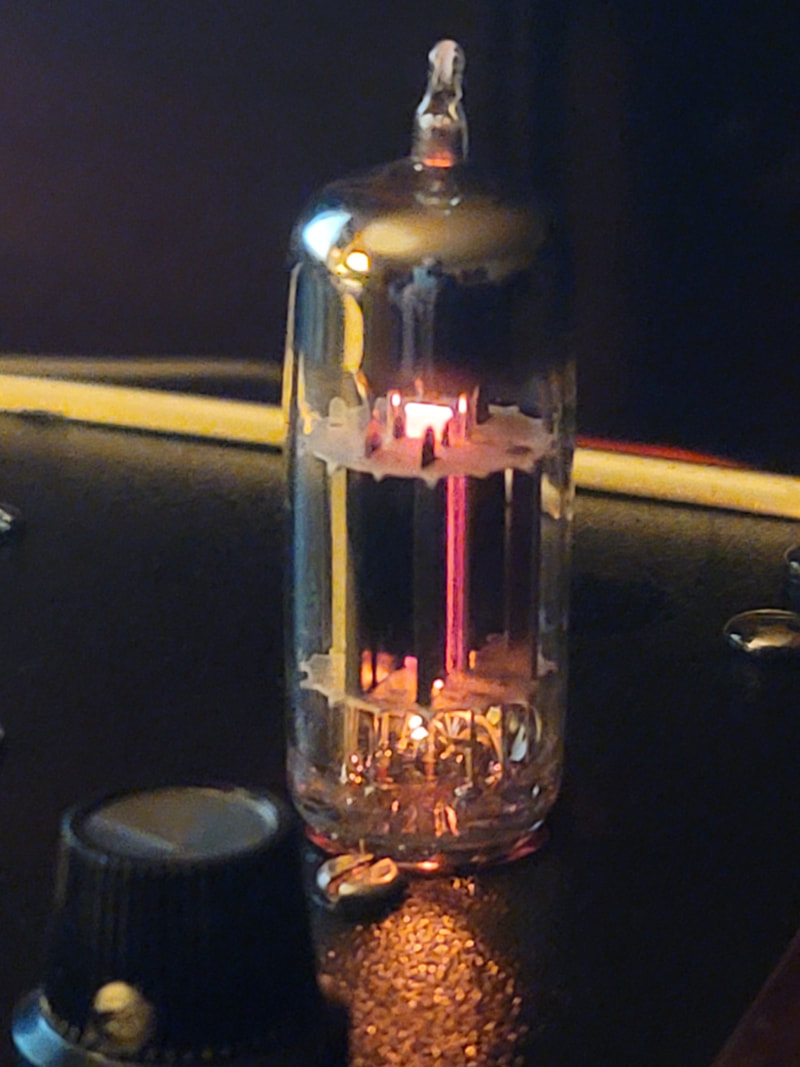
Smokin'!! (if you touch it). 10A @ 12V filament draw - only on the 8 finals (16 triodes). 28 triodes total, though 2 are unused (1/2 of the 12AX7s), and 2 regulating the Bias.

Also serves as emergency heater.  Yes, it has a "warm" tone. Freq response from about 5hz to 100khz or more. It would go down to DC but I thought it would be better to prevent that from happening. 
Picture
12B4 line Amp

I needed to get the signal from my music server across the room to the OTL amp. Though I ran all of the wire I thought I would need when the shop was built, the best I had here was 2 twisted pairs from an old S- video cable. Needed to boost the level to drop the noise floor and balance the line into the 12AX7 first stage of the amp. It also provides remote volume and balance with a slight loudness curve to compensate for losses.

AGAIN with the "these are not audio tubes" thing.
Picture
12B4 triode.
Picture
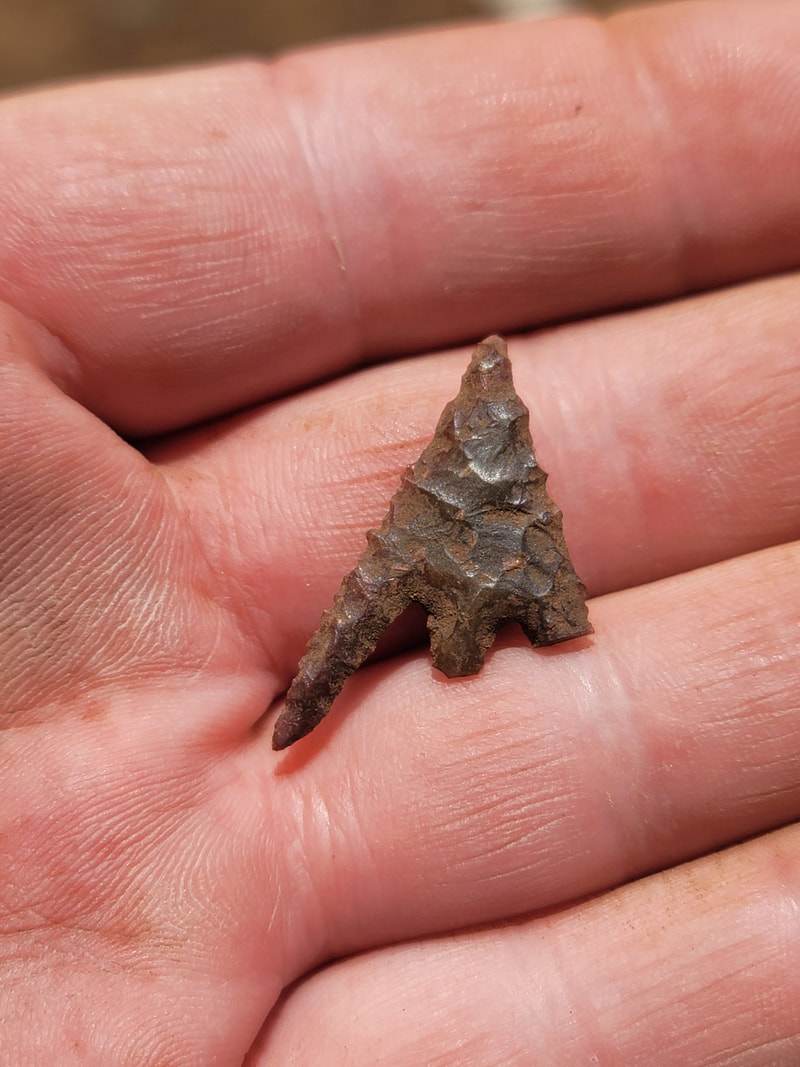
Takelma People projectile point, 200 - 1000 years B.P.,C.E.

As a result of the clearing needed to control wildfire, weeds were removed and the ground was exposed. We began to find arrowheads around the house. Compared to those I found as a kid in MO these are tiny and very intricately carved- and mostly broken, but still very cool.
Picture
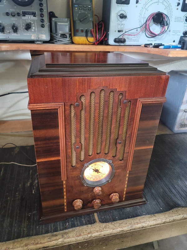
Zenith 808 from 1935 (Stewart Warner)., given to me by Bill Meyer, station manager/DJ at KMED Medford. (Now FM only)
Picture
All of the caps and most of the resistors needed to be replaced.
Picture
As Found
Picture
Same as it ever was.

​Finished. Yeah, that Solar cap was not original.
Picture
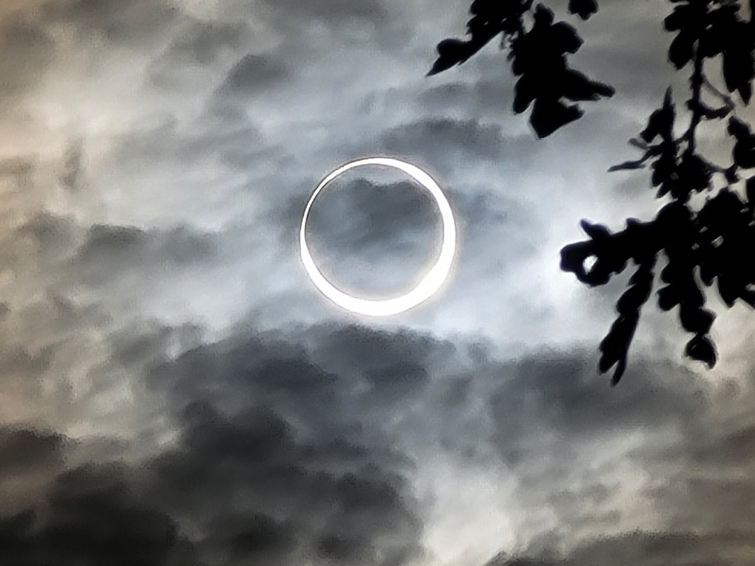
"I'm not missin' a thing, Watchin' the full moon crossing the range", annular eclipse 2023, back 40.
Ridin' The Storm Out
Picture
Picture
I had to teach my new assistant, Teddy Bear, to ride an ATV.
Picture
Picture
Chasing our tails.
Picture
Long shadows at the end of another day.
1 Comment

Dolly Strikes a Pose

3/13/2023

0 Comments

 
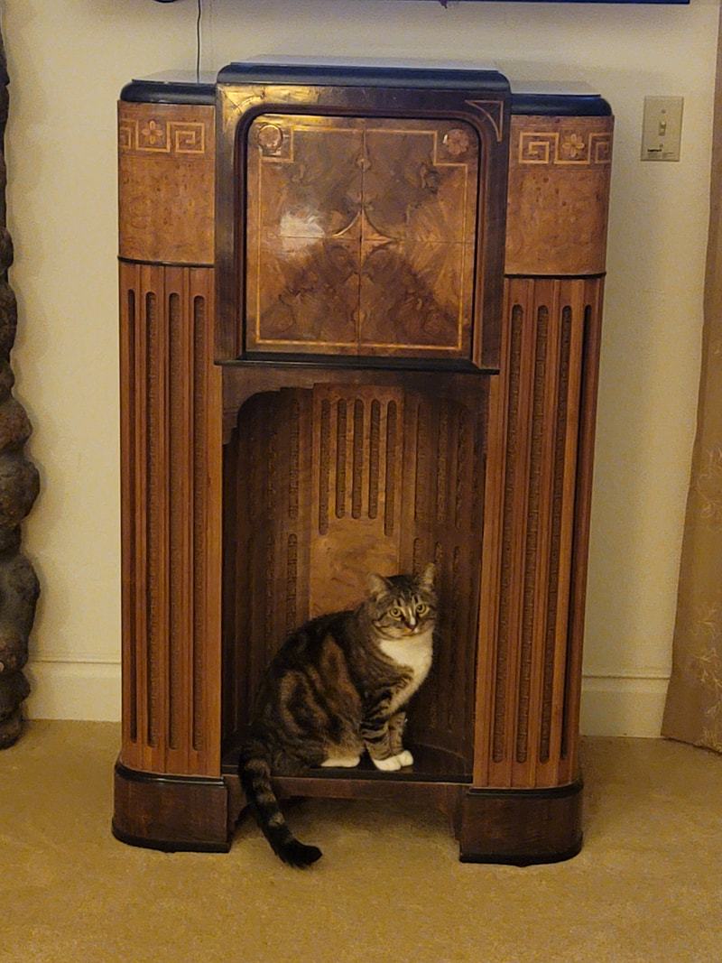
You don't know how many years I tried to get Fuzzy (Radio Shop Cat) to sit here - -
Picture
Just too busy for that nonsense. And a bit too large.
Picture
Now, if I can just get her to sit there when people visit.
Picture
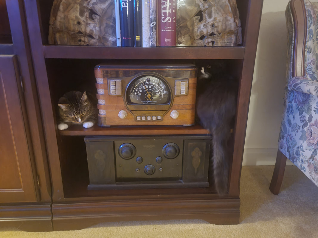
Dolly is a very looong cat. Wrap around radio warmer - -
Picture
No job is too difficult.
Picture
Ready to go, 24-7.
Picture
Let's go fix something. The more mice - er - tubes, the better.
P.S. To my friends over at ARF: Shortly after posting a link to this blog, my login became "inactive". Maybe someone over there does not like cats. I don't have time to mess with it, so you won't see me posting there anymore.

​Russ
0 Comments

Testing/Matching Audio Output Tubes
11/1/2022

2 Comments

 
 - - - or any large signal tube.

If you can tolerate shopping for tubes on E-Pay you will often encounter the claim that an audio output tube is "tested" or that a pair is "matched", OR that a pair is "NOS", tested and matched. So what does this mean and why is it important?
Well - - "matched" can and often is used to describe tubes as appearing the same, same manufacture, maybe the same date code. Sometimes "NIB" (new in box) is claimed because the tube is in a box with the manufacture matching the label on the tube. These claims are often made without "testing" at all. Often an inexperienced seller will use what he has seen as KEY WORDS in ads placed by experienced sellers. These sellers often don't know if the tube is good or not.

Some sellers are actually trying to be accurate, which is a good thing considering the consequences of making false claims - the loss of a sale + round trip shipping. The problem  lies in both understanding and capability of the person making the claim.

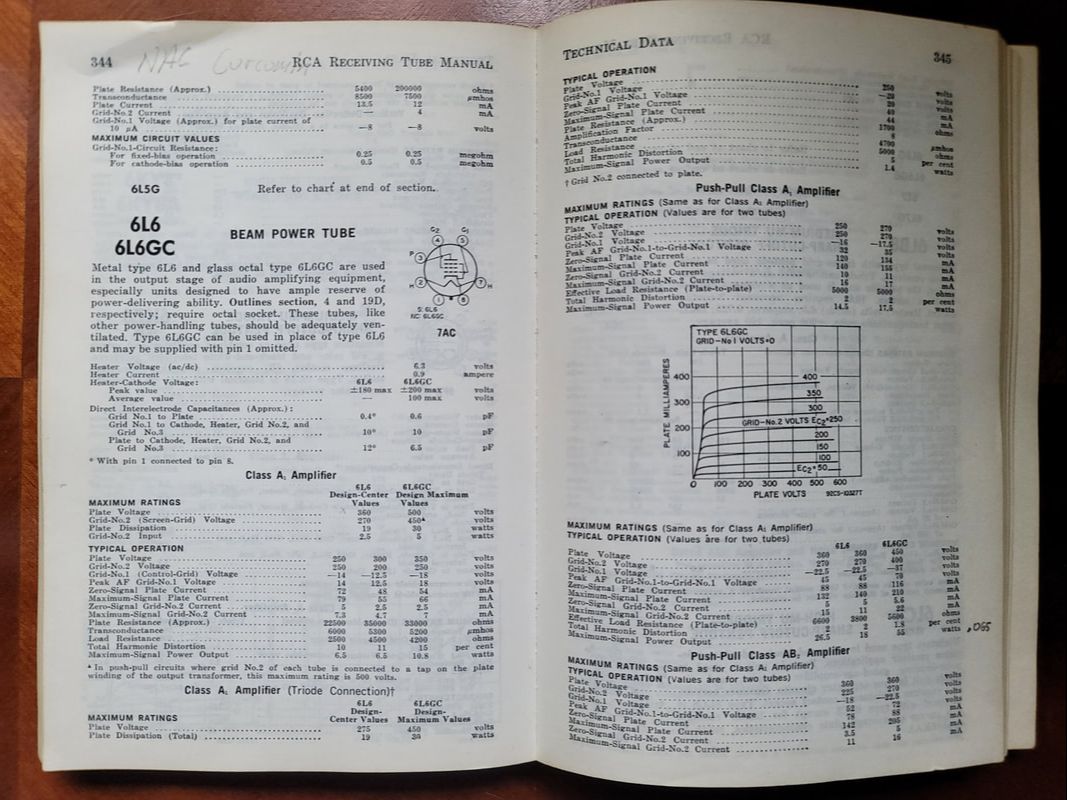
First let's consider new tubes being sold by a real manufacture. I certainly think that claims made by RCA, GE, Mullard and other traditional manufactures of a bygone time were mostly legitimate and accurate. Todays manufactures should also be able to make legitimate claims. Retailers may muddy this picture, but for the purposes of this article, I will exclude claims made by the actual tube manufacture. What's more, the expected  test values are often those stated in manufacturer's spec. sheets. Here we will often refer to the specifications (specs) listed in the RCA tube manuals.
Picture
Everyone interested in tube-type equipment should have one of these manuals
There is much more about tube testing already published. My point here is to help you determine what claims are accurate and how to verify them. So, what do the terms mean and how can you test tubes against values given by sellers or just for your own application?

N.I.B.  - New In Box, never used beyond testing.
Matched Set - A pair of tubes of the same manufacture, similar date of manufacture, which perform nearly equally in all respects throughout their operating range. - for all practical purposes, identical.
N.O.S. - New Old Stock, same as N.I.B. only the box may be missing.
Tested - Covers all extremes from "testing" the filament with an ohm meter to testing with a high-end tube tester.

A matched set of tubes makes for an easier installation especially in an amp that only has one bias pot per channel.

There are many more terms that refer to condition in some way. Many of them don't make much difference to the average user.

Picture
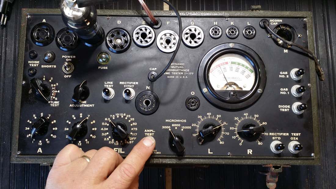
A "tube tester" , often depicted with a tube being tested and a finger pushing the button by people selling tubes. Hickok I-177 US Government issued tester from the 1940s
"A tube is best tested in the appliance in which it is meant to operate." Which is true as long as that test isn't simply PLUG & PLAY.  A "small signal" tube like a 6BA6 or even a 12AX7 can generally be accepted as OK if the device it is in operates normally. This means that it does work to some extent but the tube may still be weak. It probably does not have a shorted or open filament (heater) or the tube would not light/work at all and the pilot lights are on and the power transformer is not smoking (!! there are many drawbacks to testing in the device for which the tube is intended).

Simply stated - the more testing you can do prior to placing a tube in service the less likely you are to experience a bad/smoky outcome.

Even the simplest tube testers have a filament check function or this can be done with a V.O.M. (volt ohm meter). Yet, even here frustration can mount do to a high impedance short that can't even be seen until the tube is hot. I have swapped out so many 227 tubes or even 12AX7s because of a filament cathode leak which produces a "leaves rustling" sound in the output.  So even this simplest of tests is not to be taken lightly.

But there is so much more. The issue above is one found in both large and small signal tubes. What else should I consider while testing a tube? Just what can a tube tester tell me? Here is list of tests and terms associated with testing and using vacuum tubes.
​
Shorts - Most common and probably most important. Results range from low resistance (seen on your V.O.M.) to high impedance which requires accurate calibration even on your high-end tester. Remember, this test not only covers a direct short as seen on your VOM but high impedance shorts like the noisy heater/cathode short that could measure in the tens or even hundreds of thousands of ohms. Tests should be done with the filament lit at normal operating temperature.

Filament/heater voltage - An AC or DC voltage applied to the tubes filament. Needs to be an ACCURATE setting for ALL tubes listed in the tester's charts. Assuming that the builders took filament voltage sag into consideration is a fools errand. If the tube is designed to operate at 6.3 volts anything outside of the normal range (slightly more or less than 6.3V) Will lead to a poor prediction of actual performance. I once heard "I wish that I had known that prior to throwing out a lot of low-testing 245 tubes."

This is probably the most unreliable function of MOST tube testers. It will be of particular concern when testing power tubes with low voltage filaments like the UX-245 (early 45).

Most testers have a "line voltage adjustment" beyond the rotary switch that indicates which filament voltage tap you are using. So this addresses the problem - right? Yes, up until the time that you push the "test" button. Even a small signal tube with a 2.5V filament is going to draw considerably less B+ current than the UX-245. So when you set the filament at 2.5V, then use the line setting to adjust the meter to the "set" point the difference in B+ current is going to cause the filament voltage to sag since most testers use the same transformer to generate all test voltages. For the test to be accurate a tester would need to realign the set point while the test is being performed. Few testers will allow this, having only one meter, you cant push "test" and look at the filament set-point at the same time. Beyond that, most testers only have limited calibration adjustment for the filament transformer. Most techs try to get the filament voltage right in the 6.3 to 12.6V range, where most tubes operate. This usually leaves the ends of the range - below 5V and above 12.6 - to settle where they will. Some testers have a filament transformer separate from the high voltage transformer to reduce sag in the filament supply caused by a load increase on the B+ while testing.

Hint: While testing a tube in one socket, use another socket to monitor the filament voltage while the test is performed.
Example: While testing a UX-245 in the 4-pin socket (UX), use your VOM to check the filament voltage on the 5-pin socket. A tube with the Hickok "J and R" settings will work but a tube like the 12AX7 , "E and V" settings will not. But you can modify this to work in most cases.


B+ or Plate Voltage - This is the high voltage applied to the plate during a test. Generally the B- voltage (or close to it) will be on the cathode. The screen voltage is often derived from the B+ source. It is DC. It needs to be close to the plate voltage seen in actual operation in a device. It is also subject to sag.

B+ in most tube testers is limited to around 100V. With many small signal tubes like the 12AX7 this is adequate to simulate conditions in a device. For a tube like the 6L6GC this is far below normal operating conditions which can approach 500V.


Screen Grid (G2) - Usually derived from the B+. A positive voltage that is often about 80% of the plate voltage. Screen voltage in a power pentode is applied to the middle of 3 grids. It's value can influence the output of the tube greatly. Also poorly addressed in most tube testers due to the low B+ available.

Control Grid (G1) - The signal voltage is applied to the grid closest to the cathode.  This is the signal used to drive the tube. Most tube testers used an AC signal. Early testers like the I-177 injecting 1/2 V which can overdrive some small signal tubes. Bias is the - (negative) DC voltage applied to this grid to control the tube and prevent excessive current flow. With 450V applied to the plate of a 6L6GC, the negative bias voltage is around -37V. A tube tester capable of testing a tube to its max values must also generate this voltage. Most tube testers can't but don't need to because of the low B+ they use.

Suppressor Grid (G3) - Usually at or near the cathode voltage. Close to 0V (B-). Not usually accessible or adjustable in tube testers. It helps to keep stray electrons from hitting and changing the operation of the other electrodes.


Picture
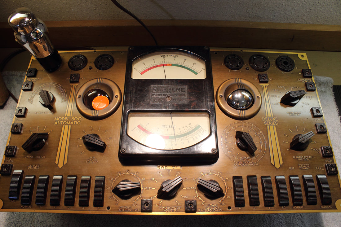
Supreme 500 Tube Tester 1937

The old adage says that if your tube tester indicates that a tube is bad it probably is. If your tube tester indicates that a tube is good, it might be.

Other than detecting shorts, what can a tube tester tell us?

An Emissions Tester will will display a value on it's meter that is often a number between 0 and 100. I am resisting calling this a percentage, but some do. Generally the scale is red-fail, green-pass and yellow-?. The yellow area is usually centered around 50 or 60.

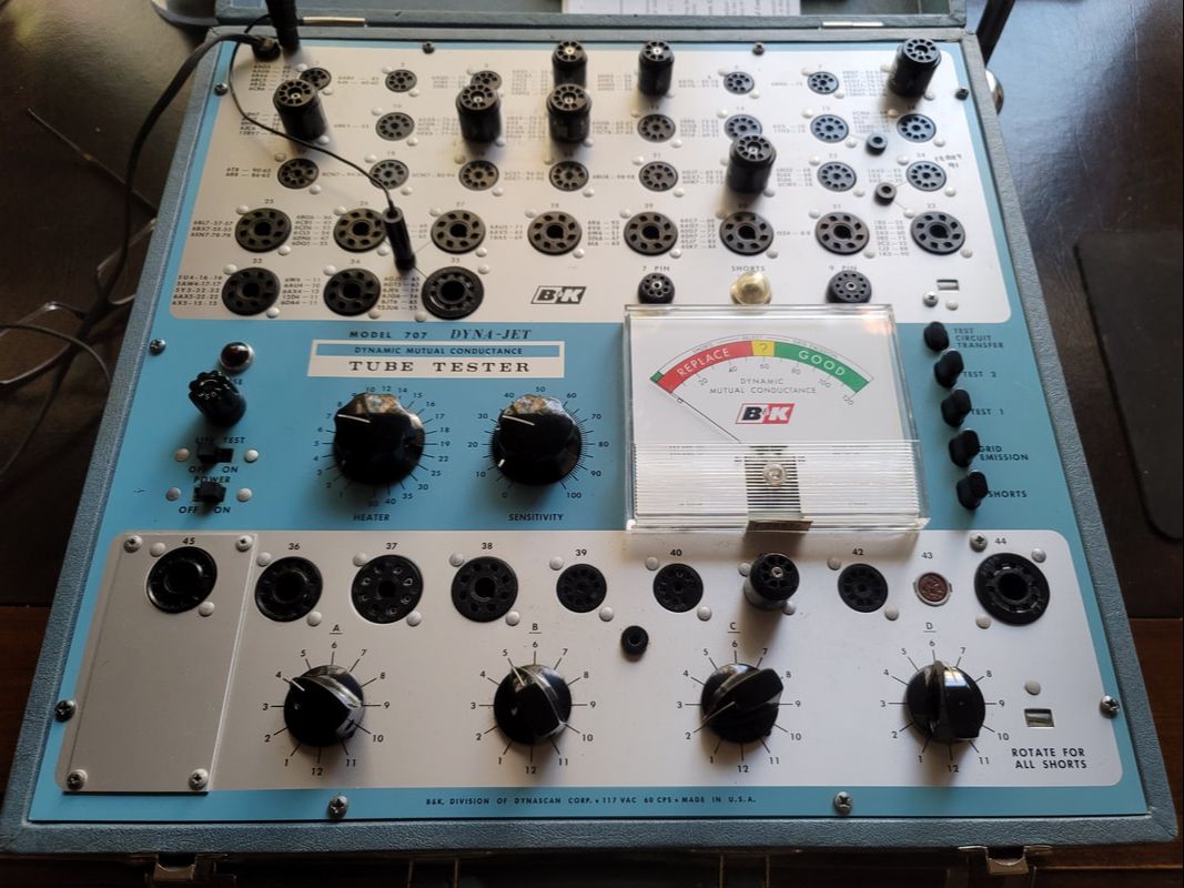
Emissions testers are generally OK for small signal tubes, pass/fail. They can fall short when it comes to power output tube testing. I'll give you an example: One of the OP tubes I often use is the 7868. It is closely related to the 6L6 and really close to the 7591 with a different base (novar). My Hickok testers all lack a novar socket. The only tester I had that could test the 7868 was a Dyna-Jet 707. Though it is a mutual conductance tester, there are a few types that it will only test for emissions. The 7868 is one of them.

Mutual Conductance - Measured in mhos or micromhos this is the preferred measurement for tube users. Mhos is the opposite of ohms and ohm spelled backward. The process was made popular on Hickok designed testers though some Hickok designed testers were built by other companies (contract TV7s). Others also designed circuits to achieve a similar end. Some testers, like the TV7 used the Hickok circuit but displayed the readings on a numeric scale rather than mhos. Also, to add confusion, some test charts specify a reading that is what they thought a new tube should read, so you had to apply your own failure calculation - now is that 50% or 60%. Some gave you a minimum value below which a tube was considered "bad". The expected mhos reading can vary from one tester to another even in the same brand. That could be expected due to the difference in signal level and plate voltage applied in the test. - - - Confused? You'll get used to it. I recommend further reading for sure.


Following the shorts test, all of the 7868 tubes that I tested on the 707 would pass at around 85. It did not matter whether the tube was new, used, or very used. This really points to the shortcomings of this type tester. I had one very used tube that read around 80. The fact that all of the others were slightly higher made me uneasy about using this tube - but it still passed - for what that is worth. Keep this tube in mind, I'll get back to it later.


Picture
Dyna-Jet 707​
The 707 has a very useful feature not found on many tube testers, a Grid Emissions display function.
All of the drawbacks found in moderately priced classic testers were known to techs and manufactures. Eventually Hickok produced the 539 series of testers which became more versatile as the series progressed. They knew that a tester that more closely matched actual operating conditions was needed.

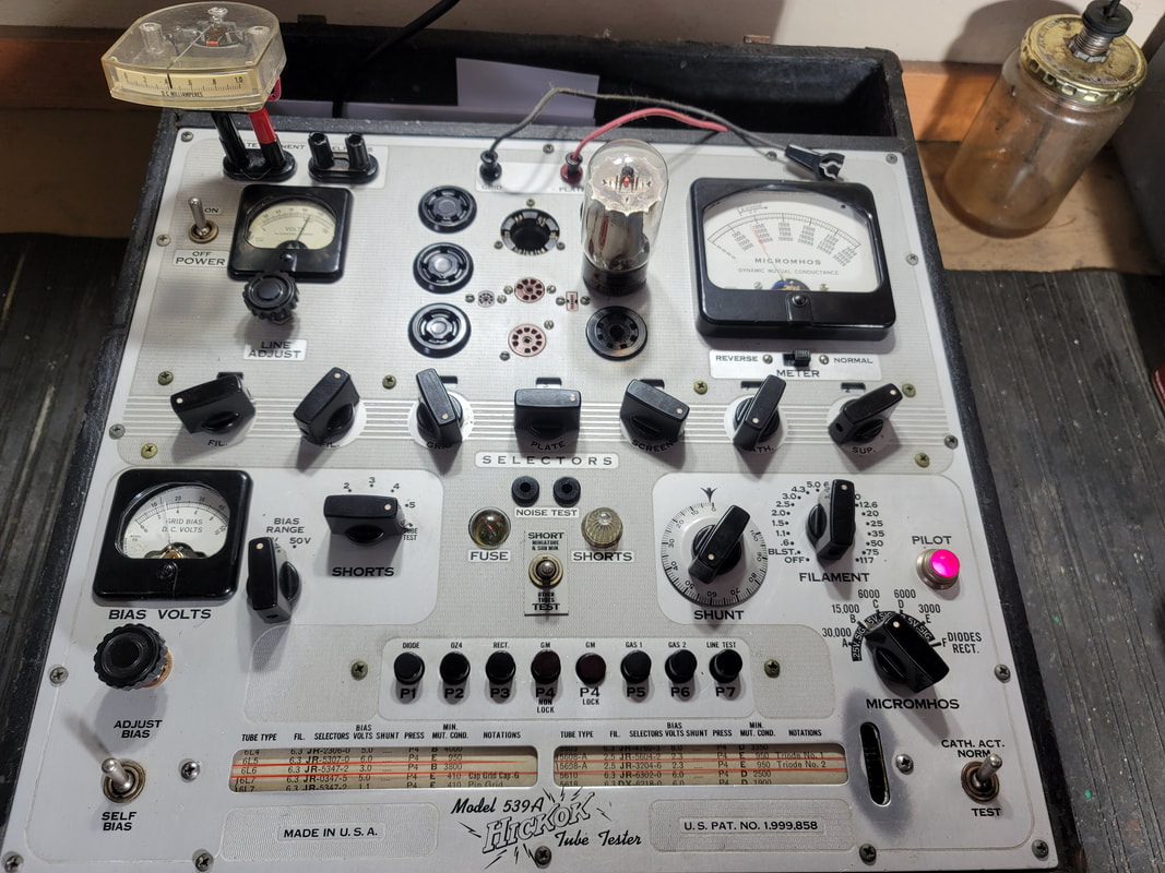
There were a few lab-grade testers but they were quite limited in availability and had high prices THEN. Now they are rare and WAY beyond most peoples budget. Hickok introduced the Model 539 in the middle/late 1950s. It was still expensive and probably beyond the average amateur tech in complexity of operation. The 539C was the latest model. It is a upgrade to earlier models in many respects.

In modern times several testers were developed to accommodate the need for testing power tubes. The Amplitrex is one that is sometimes mentioned in references to matched and tested tubes. It appears to still be available "new manufactured in small quantities". Price is not listed by the manufacture but my research found prices in the thousands of $. I have never tested one of these but they seem to be able to overcome some of the earlier testers shortcomings. Having not used it, I can't offer a review, though there are reviews on-line. Here is the company's site:            https://amplitrex.com/
Picture
Features of the 539 were:

B+ supply could provide about 180V to the plate (closer to 200V on the B,C models)
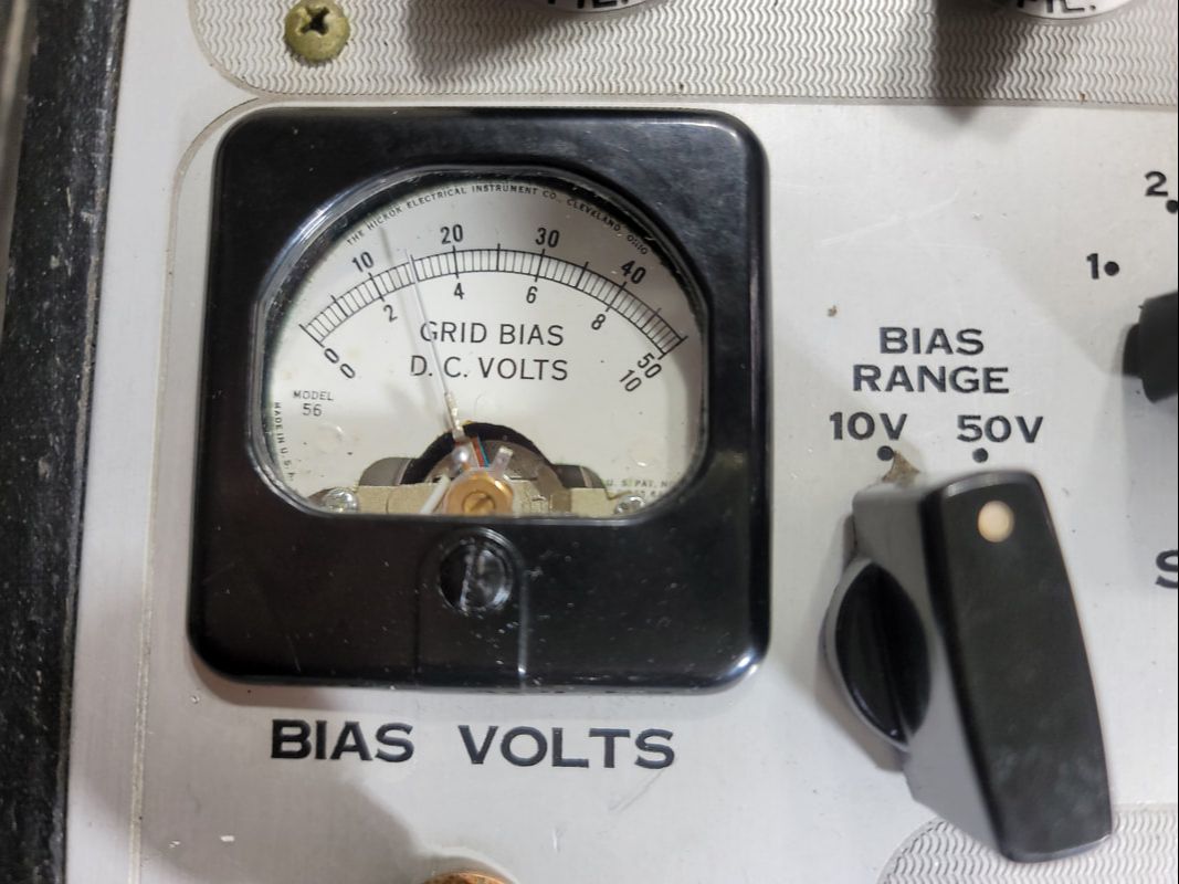
Negative bias could be set by the user and it is displayed in volts on 2 scales up to about -45V (actual).
Signal voltage can be 2.5V or .5V (AC)
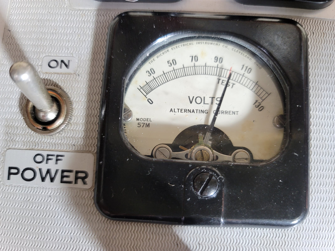
Line voltage is displayed and adjustable during a test (red "set" line = 100V). "Test" button can lock.
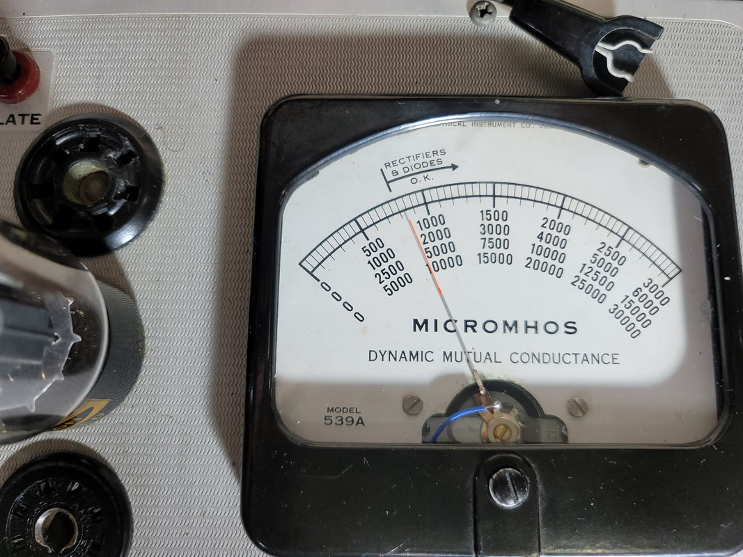
Tube performance in mhos on 5 scales
Output for plate current meter/shunt -  meter optional
Output for grid current meter/shunt - meter optional
Separate  high voltage and filament transformers
I mentioned above that no tube could be expected to perform to spec with a luke-warm filament caused by sag. You can see here that the test parameters were adjusted to compensate for the lower B+. Note that the -bias for a 6L6 is only -3V which is in line with lower voltage (180V) on the plate. The expected output in mhos is also lower than a tube with higher voltage on the plate. (The mutual conductance varies with the test parameters). Filament supply sag is addressed by being able to set the line during a test and a filament supply separate from the HV supply. So manufactures were able to adjust the expected results to accommodate some of the limitations.
Picture
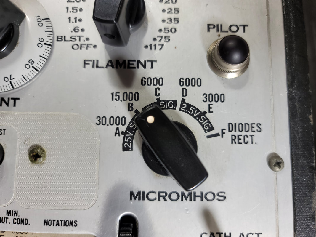
Variable mho scales as well as variable signal level
I had to replace all of the meters due to really poor packaging. The guy I bought this tester from broke down a box and then wrapped it around the tester with no padding. You don't have to dent the case to ruin the meters - but that is another story.
Picture
-3Volt bias
Picture
Reset the line level - missed a little didn't I?
Picture
This 6L6GC tests at 4200 micromhos. The minimum listed on the roll chart is 3800
Picture
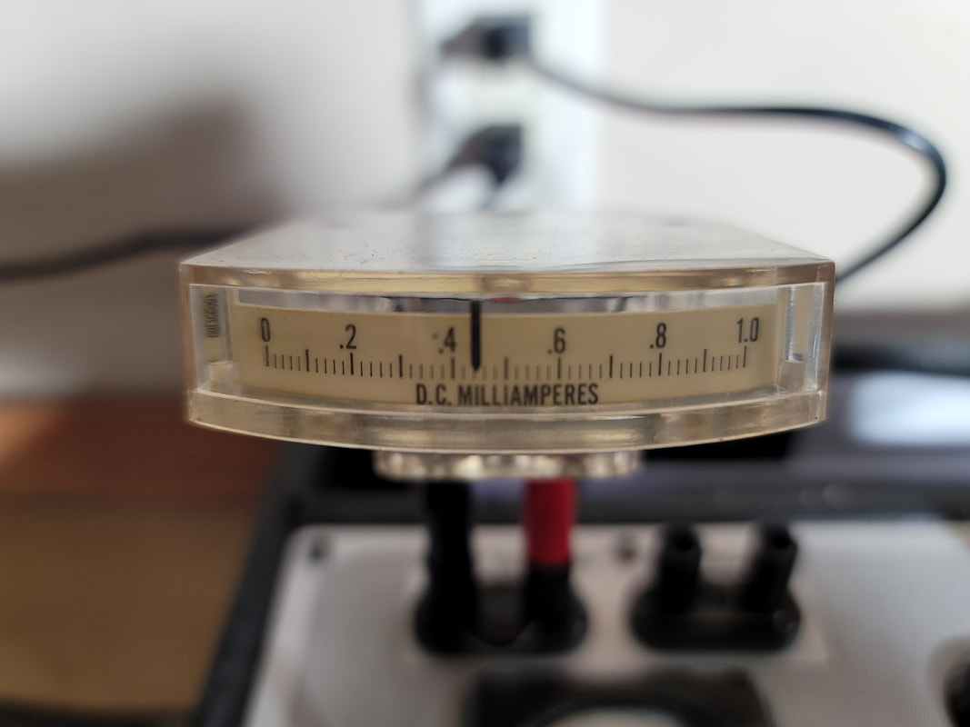
Around 44 mA using a piece of nichrome wire for a shunt
The plate current meter is not incorporated into the 539 but a set of contacts are. If you install a meter (recommended) you will have to change the value of the shunt, which comes with a shorting bar (remove). I used about an inch of nichrome wire as I recall about 29 ohms/ft. The meter is labeled in fractions of a milliamp but with the right shunt I made it read in mA x 10 without the decimal. Fuzzy, in the lower right is the break-out for grid current. I need to get another meter in there. IMHO this mA measurement is at least as important as the measurement of mhos because this is what you need to set up your amp. Tubes should be matched to output in mA at rated power with negative bias the same or very close.
  What is a reasonable solution to the shortcomings of tube testers?
 Build your own tube tester. The best vintage testers, like the Hickok 539, A,B,C and the more modern testers like the Amplitrex are EXPENSIVE(! ) And difficult to maintain and calibrate. Some don't even have a clearly understandable calibration method (like my 539A). Some have limited testing charts (like my 539A). You can avoid all of this building your own.

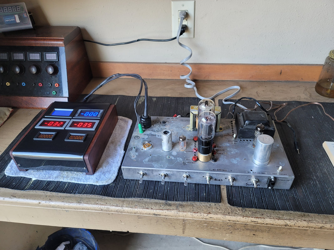
Cost to build my tester was a little more than $100. You may already own an old PA amp which is not really suited to use in your hi-fi setup. (Audio quality aside, They are kind of ugly especially when you stack up 2 of them).  The meters I used are cheap on Pay-Bay (around $10ea for Chinese made). All of the rest of the parts came out of the junk drawer (inventory). It came with 2 VERY used 7868s. I have a push-pull 7189 amp which I intend to configure for the 6BQ5 family of tubes. My 6BQ5 tester will use the same plug in display.

The adaptors, 7868 to 7591 and 7591 to 6l6G,GB,GC are also available on P-Bay, or build your own.
Picture
Bogan CHP-35 Amp in it's new life as a tube tester but still allowing the user to listen to the tube/tubes being tested.
This project will take some tube experience/knowledge and the associated tools and skill. I think that a lot of my readers do have the tools and ability required. If you are new to tube circuits, save it for a while, but be aware of the shortcomings of what is available now and the claims made by tube sellers.​
Picture
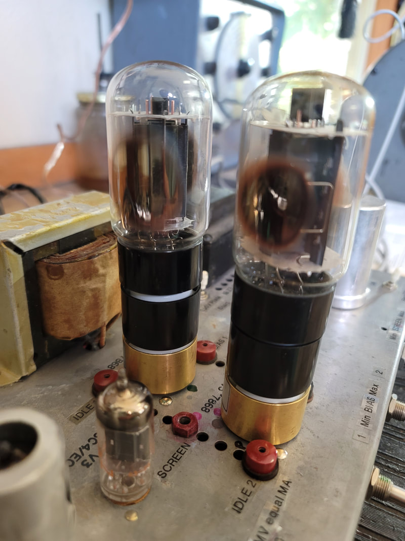
Very used 6L6GCs. Adaptors reduce the need to punch out a lot of tube socket positions, associated wiring and switches.
This pair of 6L6GCs is pretty well matched and will make full rated power, but they aren't new (or in a box). Generally, you will find that a new tube will make rated power at a higher negative bias setting. Well used tubes may not make rated power even at vey low bias settings. Because of the condition of the getter, I would use these tubes in seldom used equipment but not in a frequently used amp.

Note the brown edges on the getter. This indicates a used tube. My theory is that, temperatures of the electrodes and electron bombardment vaporize coatings and possibly metals. These can precipitate on cooler surfaces like the mica insulators unless absorbed by the getter. Note also the difference from a tube that has "gone to air" (loss of vacuum) in which the getter turns white. Red plating can make this much worse than "normal" use. Deposits on the micas of my 7868 tube probably lead to it's runaway condition. 
Picture
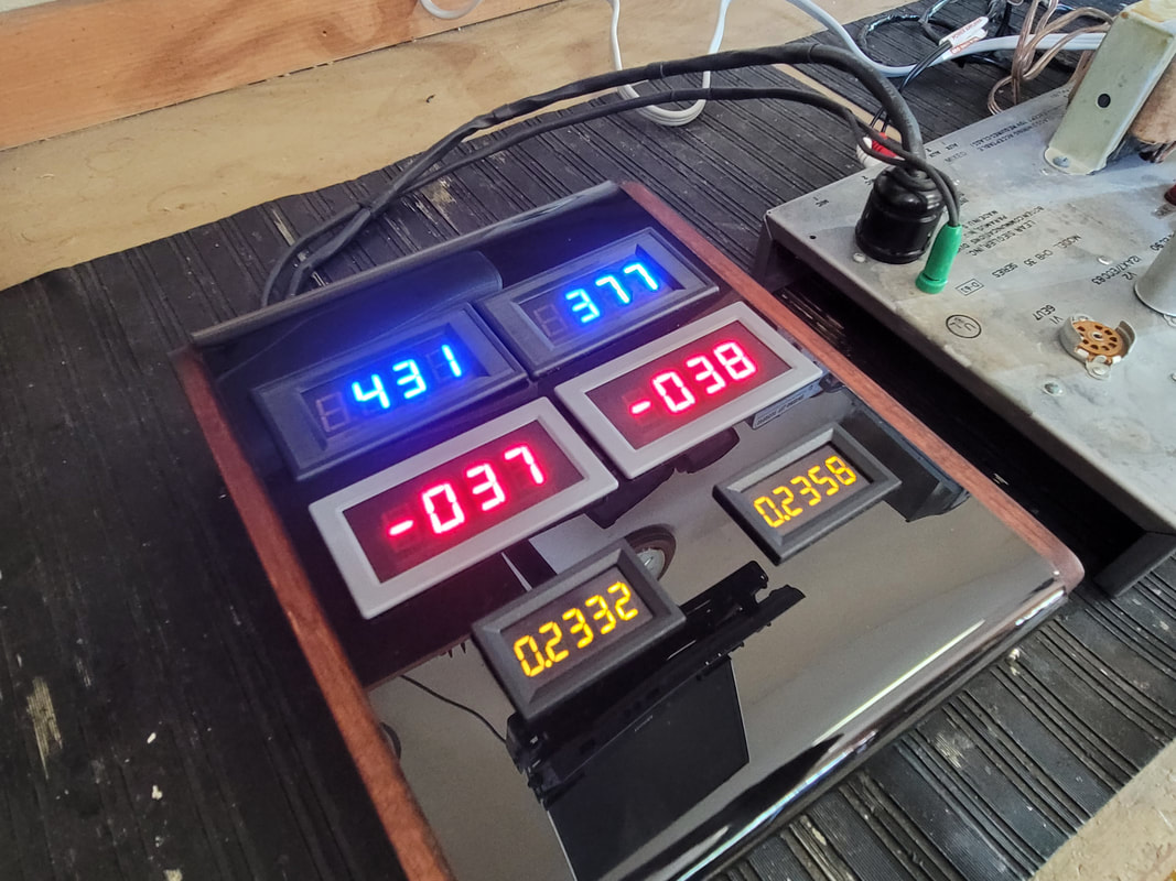
HEY! those old tubes match pretty well
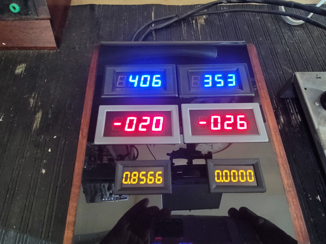
From left to right, top to bottom, the meters display:

B+ Plate Voltage       Screen Voltage
Bias (1)                         Bias (2)
Milliamps(1)                Milliamps(2)    Both must be /10 to account for the 10ohm cathode resistor, .2332 = .02332 amps = 23.3mA  Display is mV which converts to mA.

Finding meters that display down to 3 digits before the decimal is necessary for the output current and there seems to be  limited choices at this time. (accounting for the smaller size meters)

You will need to add:
A filtered supply ~ 5 - 12V DC for the meter display. In my case removing the 6EU7 tube from the Bogan saved about as much power as was required. The 6EU7 was the preamp used with a phono. The 6.3V AC filament supply is good for this.
A filtered negative bias supply. Use a full wave or bridge rectifier and maybe a voltage doubler on the existing bias supply. It needs to be adjustable from ~3V to -45 or -50V somewhat independent on each side (tube 1 & 2)
Variable control of the screen supply. There is little current needed. 1 control.
I kept my tube rectifier and added a filament on/off switch. This allows the filaments of the tubes being tested to warm prior to turning the rectifier filament on. Watching the display through warm-up allows for a quick shutdown if trouble exists. The tube rectifier protects the power trans better than a solid state rect. But, more plate voltage would be available using sand (solid state).
Tone controls can be replaced with the new controls required for testing.  (no need to drill)
I had installed test ports on the Bogan. They are handy but redundant and were used prior to building the meter box.
No more need for outdated roll charts. You can use the RCA tube manual for settings instead.
Picture
34.75W exceeding the 30W plate dissipation rating - single tube 6L6GC, Note that this test is for tube 1 only - 0s displayed for tube 2 current
This is about all you can expect from this tester. Exceeding the max ratings will damage the tube/redplate/BAD. Don't try this at home. You might want to keep your calculator handy.
Picture
Inject a clean sine wave at a known level
You can either use a speaker on the Bogan's output or install a load resistor. DO NOT LEAVE IT OPEN. Using a speaker is a real plus. You can hear what happens if you use too little screen voltage. To much screen will make more power but most people would rather save their expensive tubes rather than getting the full 35 watts out. If to little screen voltage is used, power output distortion will occur at a lower level. You won't be able to get adequate idle current.

The Bogan was built to supply 35 watts output from the pair of 7868 tubes. This was really putting the squeeze on them (She won't take much more of this Captain.). The schematic spec. was lower but testing reveled that about 410V on the screen would get you that 35W and that is where it was when found. I would recommend not exceeding the values in the RCA manual. Dropping the screen and raising the negative bias slightly will not make a noticeable change in sound but will save your expensive toobes. With this tester you can listen to the results and make changes accordingly. Don't forget - this is the tester. Anything you decide will have to be applied to the actual amp in which tubes are to be used.

AND - - should I mention that you need to know the values used in the actual device (amp) prior to setting up this tester. It is easier to adapt a 6L6GC amp to this function than a 6L6G amp. Higher B+ will already be available as well as screen and negative bias.
Picture
Use a dual trace scope to compare the input signal with the output
In conclusion:
Will your average mutual conductance or emissions tester match tubes used in high level audio outputs? No. This includes the ever popular TV7.
Will your average mutual conductance or emissions tester test tubes for quality/performance in high level, real world applications? No. 
Will your 
average mutual conductance or emissions tester test small signal tubes. Yes
​Will a cheap tube tester perform any useful test? Yes, if the shorts tester is working properly.
Can you build a reliable tester? Yes

​You can also set up your receiver/amp to test its own tubes using a VOM and a handful of parts but this is risky if you ever encounter a tube with a high impedance short (not found by a shorts tester). A runaway tube can take out an output transformer before you get your meter on the right pins. (don't ignore that hum in the output. One side of the PP outputs may be conducting a lot of DC through the primary winding). 

​I tested the previously mentioned 7868. Along side of another 7868 it was doing 8mA when the other tube was near full power.  I began turning down the - bias (becoming more +), still 8mA. Eventually I hit a bias point that the output began to rise. Without adjusting the bias further it continued to rise - quickly. I did not wait to see how far it would go. And it hit the trash can a bit later. Remember, the DJ 707 said it was OK. I did not have an adaptor to sub it into an octal socket on the Hickok 533, but I suspect, passing the shorts test, a failure would not have been indicated, though I do not know what the GM would have been. The 533 also has a relatively low plate voltage.

​There are a lot of testers not covered here. There are a lot of tubes not covered here. I have included a few of the modifications to the Bogan amp I used since the one you use will probably be different. If you have any questions, you can post them below.

I think that this will always be a work in progress.

Russ

2 Comments

New Strat-Cat, Dolly

10/29/2022

3 Comments

 
The Dial Belt was slipping. If you don't change the dial position every once in a while even the new silicone dial belts get out-of-round and slip, especially on the Zenith Strat since there is so much moving mass.

​Don't tell Dolly that she is looking at the wrong end.
3 Comments

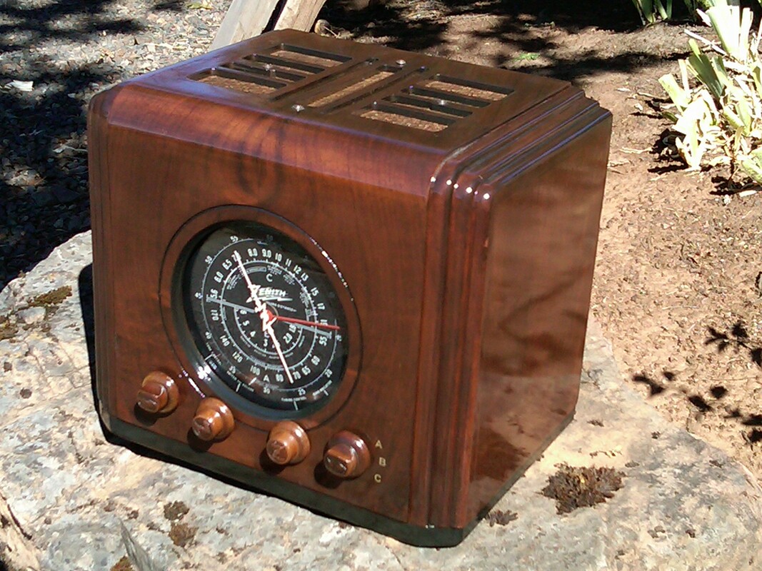
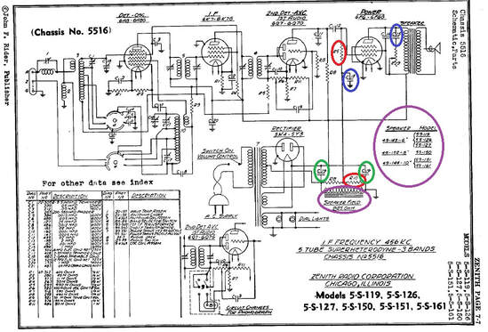
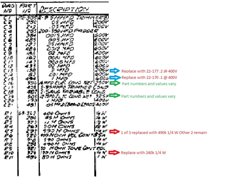
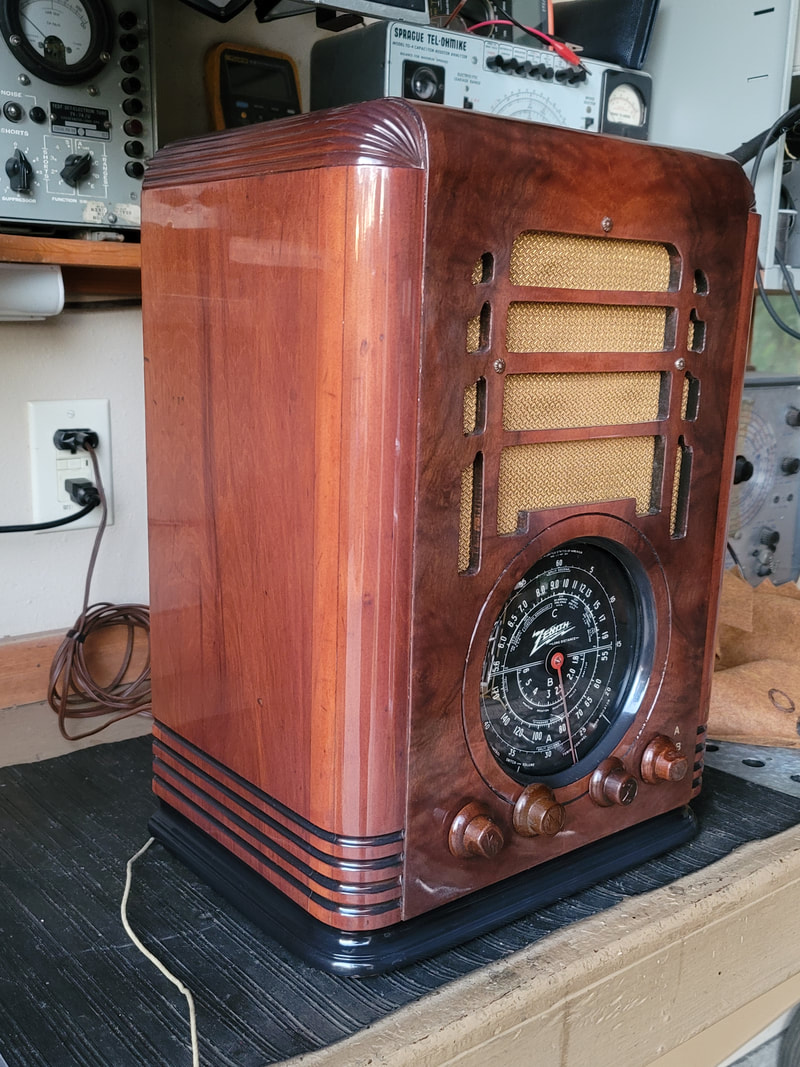
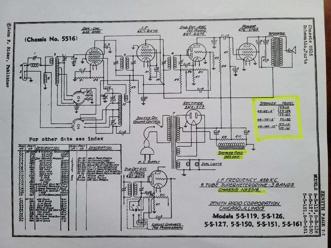
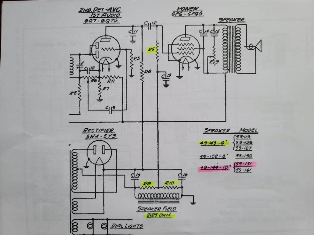
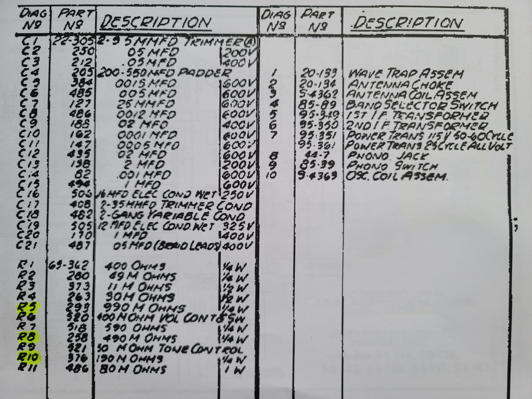
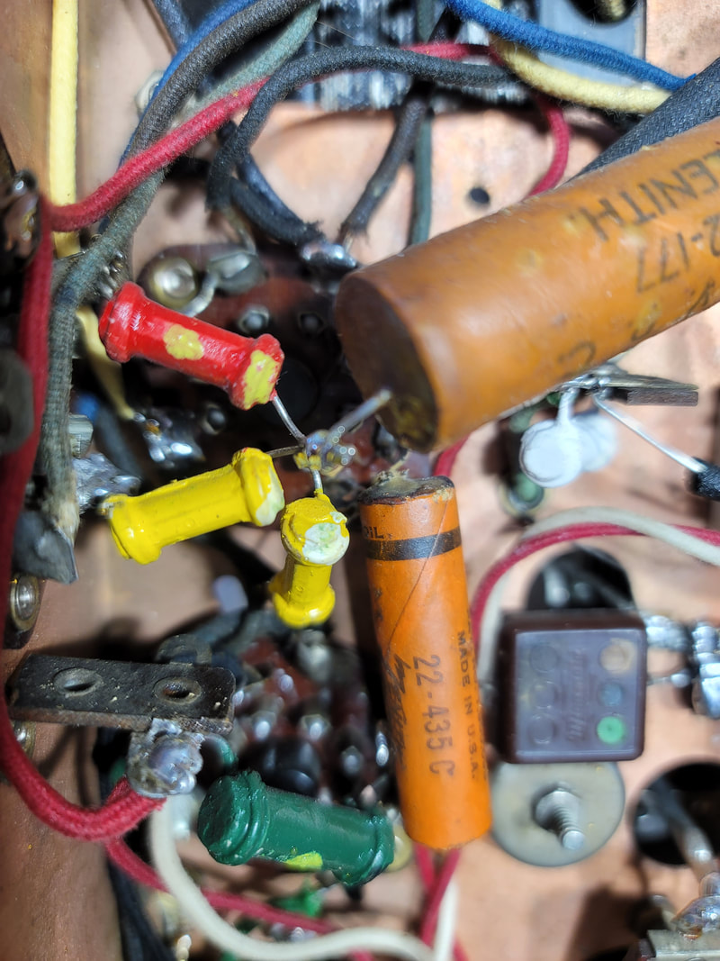
More Changes to the Zenith 5516 Chassis

7/20/2022

1 Comment

 
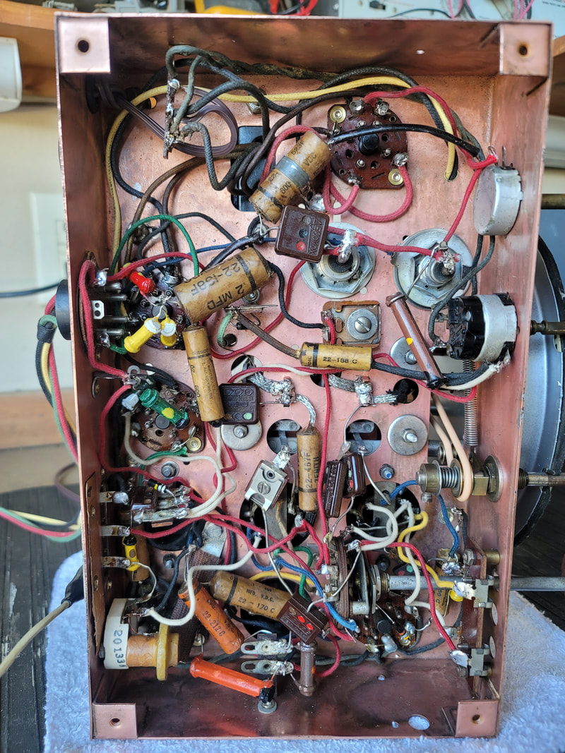
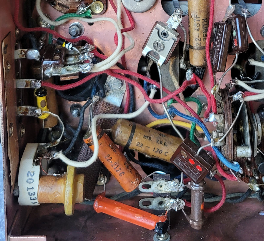
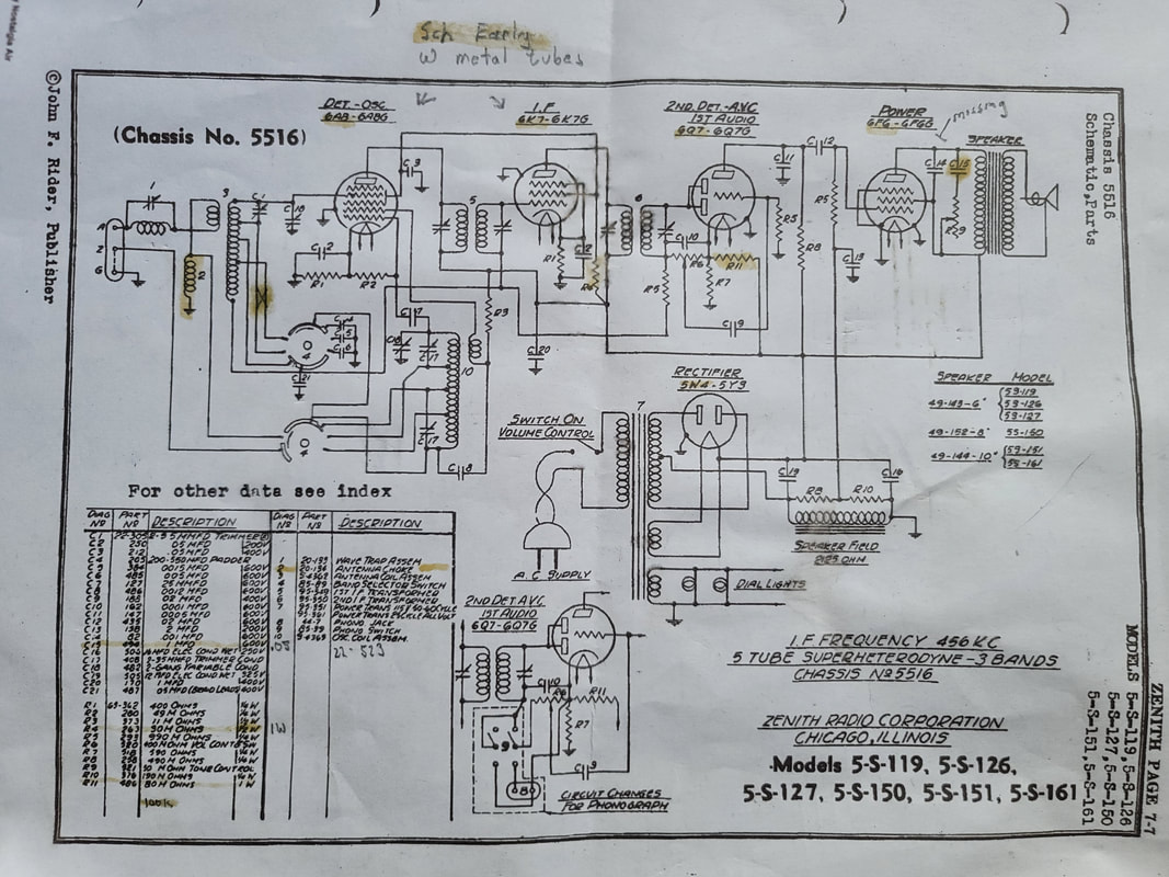
Rather than have this information/update separate from the rest of the story, I have posted it ate the end of the previous entries - "Zenith Got it Wrong" and "Zenith got it wrong Part Deux" (Duh):

https://www.russoldradios.com/blog/zenith-got-it-wrong-5516-chassis

​Russ
1 Comment

NUTS! An Update "For the Birds"

1/11/2022

1 Comment

 
Actually acorns - Oak nuts,

​https://www.russoldradios.com/blog/for-the-birds

I did not think they would last long, even after slathering them with polyurethane.

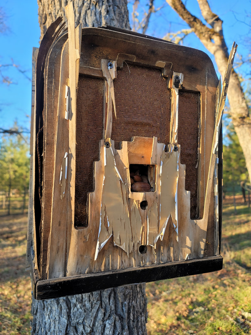
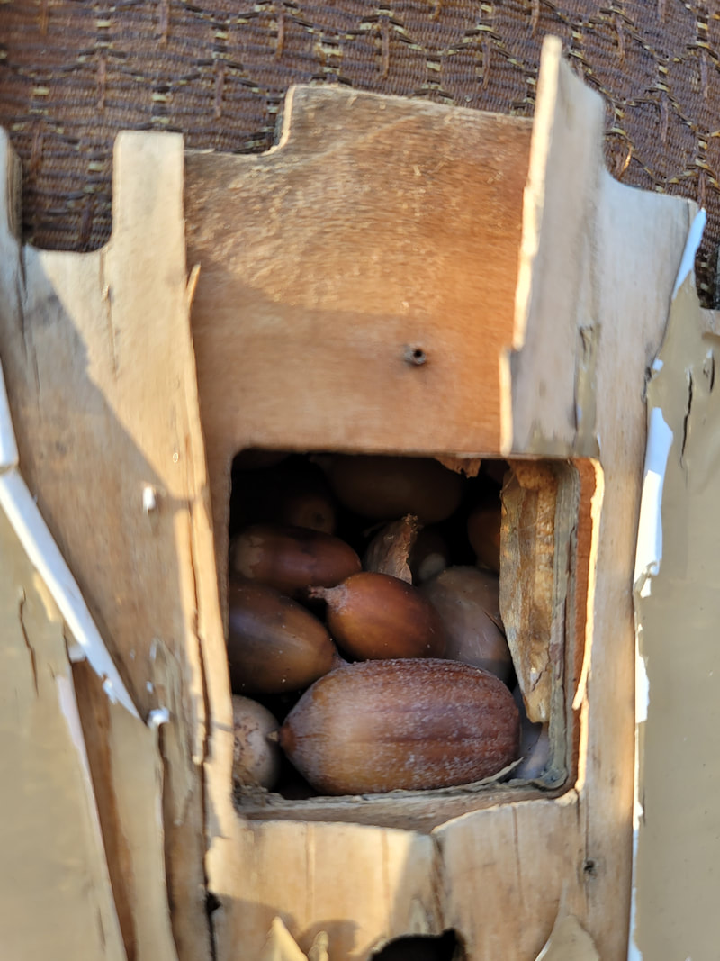
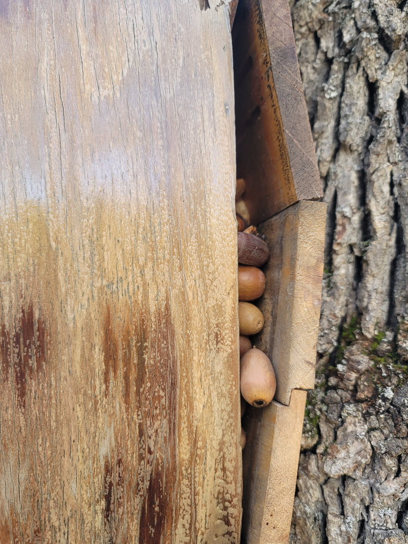
The birds never thought much of the Crosley Buccaneer. So it quietly disintegrated.. The birds found the Fiver much more interesting. Turns out it was not an eagle nesting in there ;-) but a bunch of Acorn Woodpeckers decided to use it as a store-house.

The Fiver is now bursting at the seams - filled to the top with acorns. When it was filled to the dial they began stuffing acorns through the cracks, which became wider and wider (it is near complete structural failure).

Acorn woodpeckers prefer location to tube count.
Picture
Picture
Picture
Russ
1 Comment

Seven Years Later - Update on Aetna

12/17/2021

2 Comments

 
I knew that Sue's radio was unusual  but it is more special than I had thought:

https://www.russoldradios.com/blog/old-radiosradioproject-update-iv

​
UPDATE 12-16-2021
We now know the the Aetna model is 252P under Walgreens. It is a 4-tube  + ballast Tuned Radio Freq receiver from 1936. Most of the radios found in this cabinet are 550s, which is a superheterodyne rather than a TRF.  The super is relatively rare. The TRF is much more unusual.

Russ
Picture
I know that a lot of people have wondered what would happen if a person was to design a receiver - a TRF receiver, that had one high gain tube driving another and so-on. With this chassis it is easy to find out. Like the front end in a Zenith Stratosphere this chassis has a tuned 6D6 driving another, in this case a 6C6. Well, the answer is that LOTS of RF gain can get you - squealing, motorboating and eventually  - nothing. Even in the Strat, they had to turn off one of the 6D6s on some bands to keep the noise down to a controllable level. Unlike the Strat, or any super, this radio has no IF to narrow and amplify a specific freq so strong stations can be over powering to weak stations.

With this radio it is best to decide what kind of antenna you are going to use and align the radio to that antenna. A longer antenna will provide the noises mentioned above and a shorter one will make weak stations - weak. While the schematic in Riders says not to bend the plates on the tuning cap, linearity across the band is poor. Maybe someone already bent the plates or maybe they need some adjustment, but the spot (freq) you choose to  align to is going to be the sweet spot all else going down hill from there.

​No wonder they replaced this chassis with the 550 super. 
Picture
I thought that I took some chassis pics as we updated the radio with re-stuffed caps we found over the last 7 years. I'll try to find them.
2 Comments
<<Previous

    Author

                         Russ Webb

    Picture
    Russ Webb & Fuzzy

    Best Buddy, Radio fixer


    Categories

    All
    All
    Antiques
    Electronics
    Radios
    Repair
    Restoration
    Travels
    Vintage

    RSS Feed

    Archives

    March 2025
    November 2024
    December 2023
    March 2023
    November 2022
    October 2022
    July 2022
    January 2022
    December 2021
    September 2021
    June 2021
    April 2021
    February 2021
    January 2021
    November 2020
    July 2020
    June 2020
    April 2020
    March 2020
    December 2019
    October 2019
    May 2019
    April 2019
    March 2019
    February 2019
    January 2019
    December 2018
    November 2018
    October 2018
    September 2018
    June 2018
    April 2018
    March 2018
    February 2018
    January 2018
    December 2017
    November 2017
    September 2017
    June 2017
    May 2017
    April 2017
    February 2017
    December 2016
    November 2016
    October 2016
    September 2016
    August 2016
    July 2016
    June 2016
    May 2016
    April 2016
    March 2016
    February 2016
    January 2016
    December 2015
    November 2015
    August 2015
    June 2015
    May 2015
    April 2015
    March 2015
    February 2015
    January 2015
    December 2014
    November 2014
    October 2014
    September 2014
    August 2014
    July 2014
    June 2014
    May 2014
    April 2014
    March 2014
    February 2014
    January 2014
    December 2013

CUSTOM DESIGN BY SUE WEBB  06/2013       Redesigned by Russ Webb     Approved by Fuzzy   Updated:  Pretty much all the time, but I forget to change this date
Proudly powered by Weebly
Photos from valart2008, rafeejewell