
OK, OK, the only color is green.
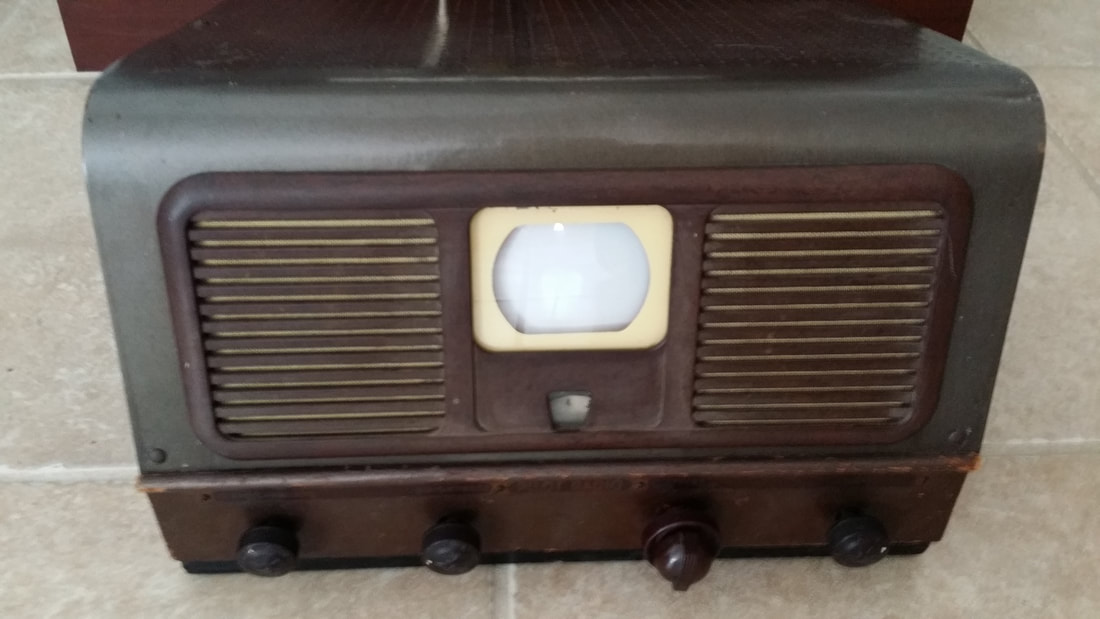
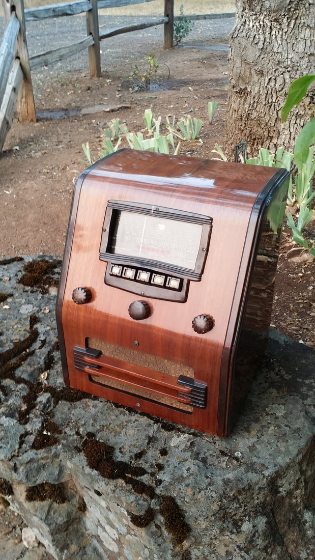
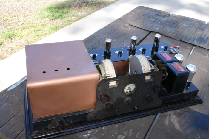
Sold in 1948, this was one of the first budget TVs. This brings back memories of long lines of people waiting for the "Black Friday" sale at Circuit City when flat screens first became the "hot" Christmas gift. These were no less popular.
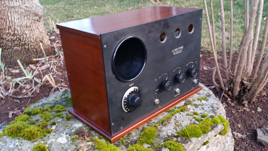
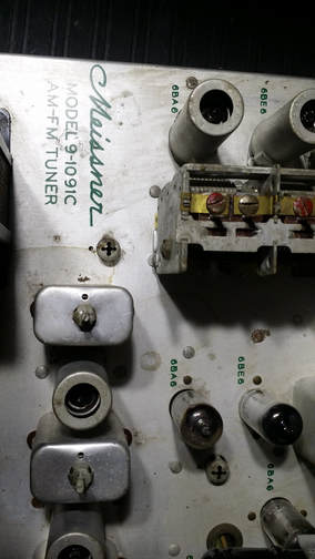
The $99 price was the best part of this TV. The real drawback was the 3" screen. Continuous variable tuning on 2 bands was a cost saver, but I find tuning to be easy, maybe easier than the click , click/fine tune two step of a conventional TV tuner.
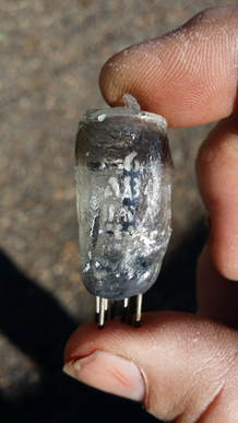
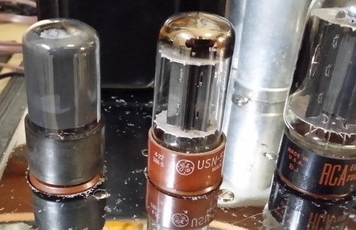
The picture tubes were not green phosphor as sold. The original CRT must have failed and prior to my restoration somebody installed a oscilloscope tube. An original replacement is very hard to find today. The green doesn't make watching a 3" tube any better.
Sold in 1948, this was one of the first budget TVs. This brings back memories of long lines of people waiting for the "Black Friday" sale at Circuit City when flat screens first became the "hot" Christmas gift. These were no less popular.
The $99 price was the best part of this TV. The real drawback was the 3" screen. Continuous variable tuning on 2 bands was a cost saver, but I find tuning to be easy, maybe easier than the click , click/fine tune two step of a conventional TV tuner.
The picture tubes were not green phosphor as sold. The original CRT must have failed and prior to my restoration somebody installed a oscilloscope tube. An original replacement is very hard to find today. The green doesn't make watching a 3" tube any better.
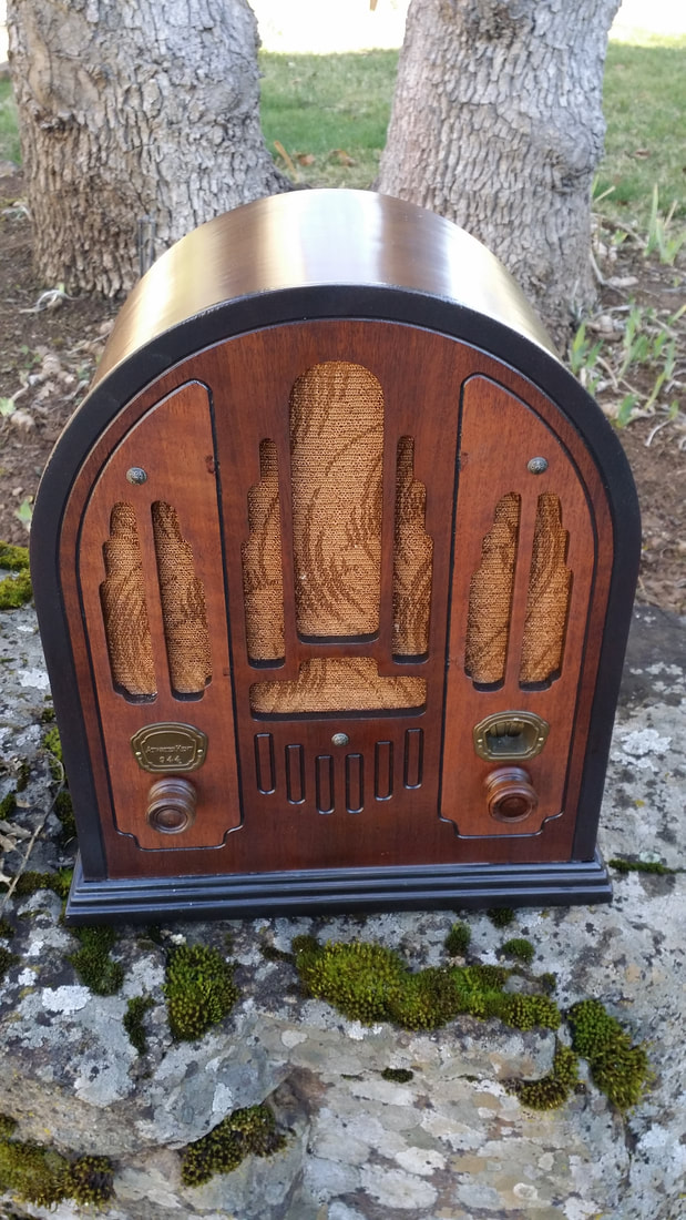
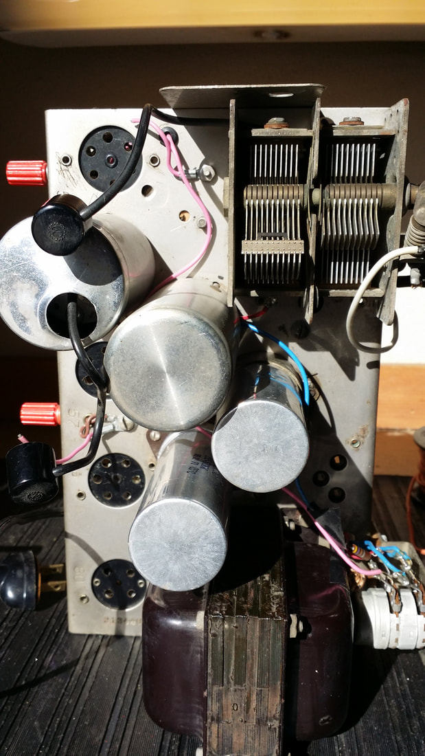
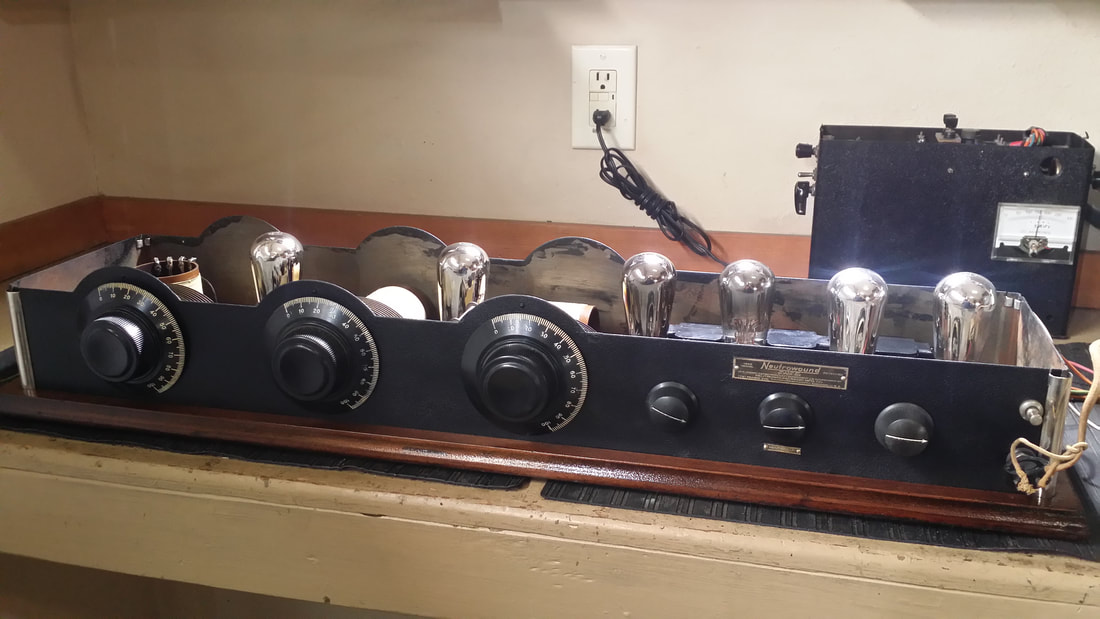
TV are not something I have not put much effort into, but I always wanted a small "roundie" TV for the museum.
It is hard to take a movie of a changing/reflective surface, but I tried: The input is from a HD to channel 3 (NTSC) analog converter - Below


 RSS Feed