
- - all visits by groups and individuals as well as community support activities at the radio shop/museum have been suspended.
We hope that everyone remains healthy and safe.
We hope that everyone remains healthy and safe.
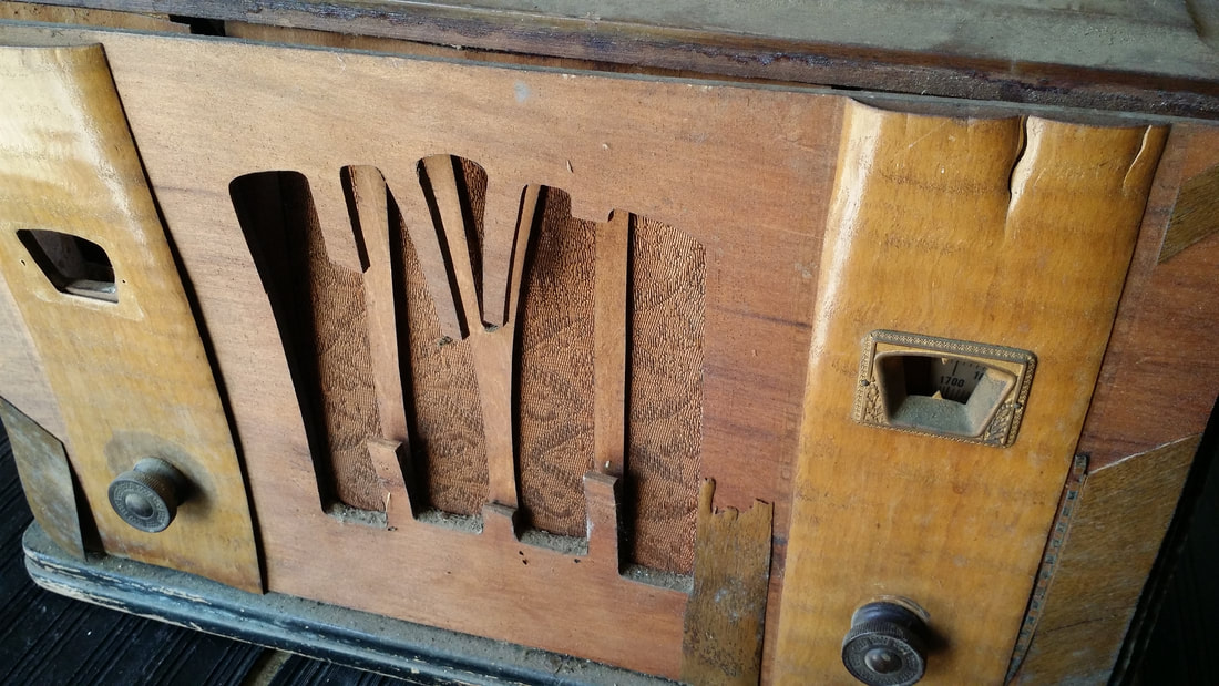
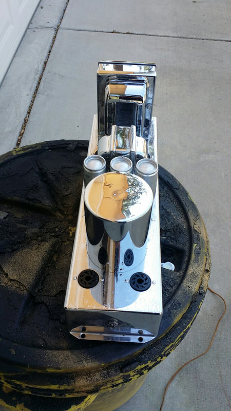
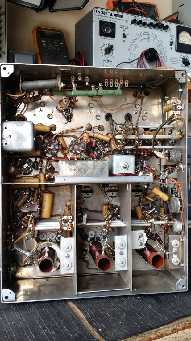
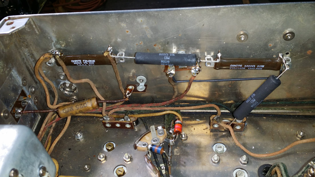
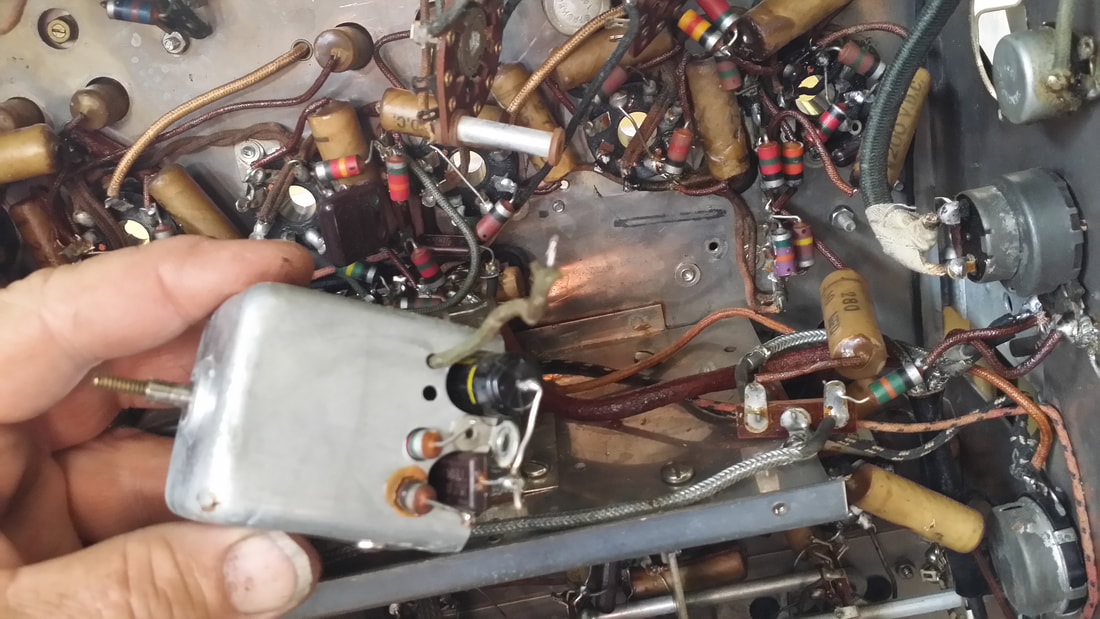
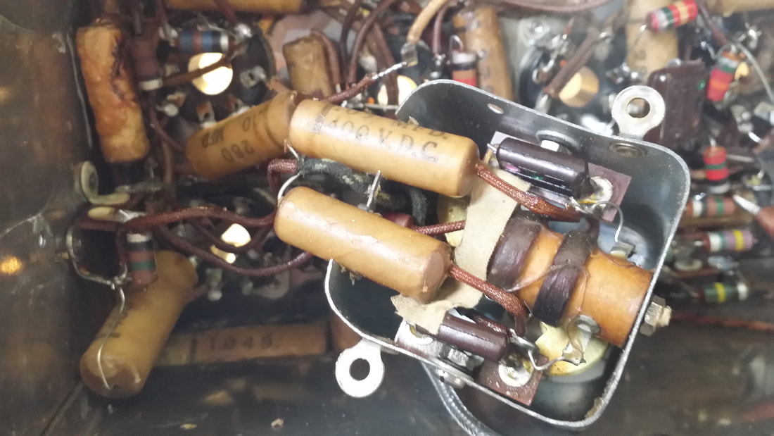
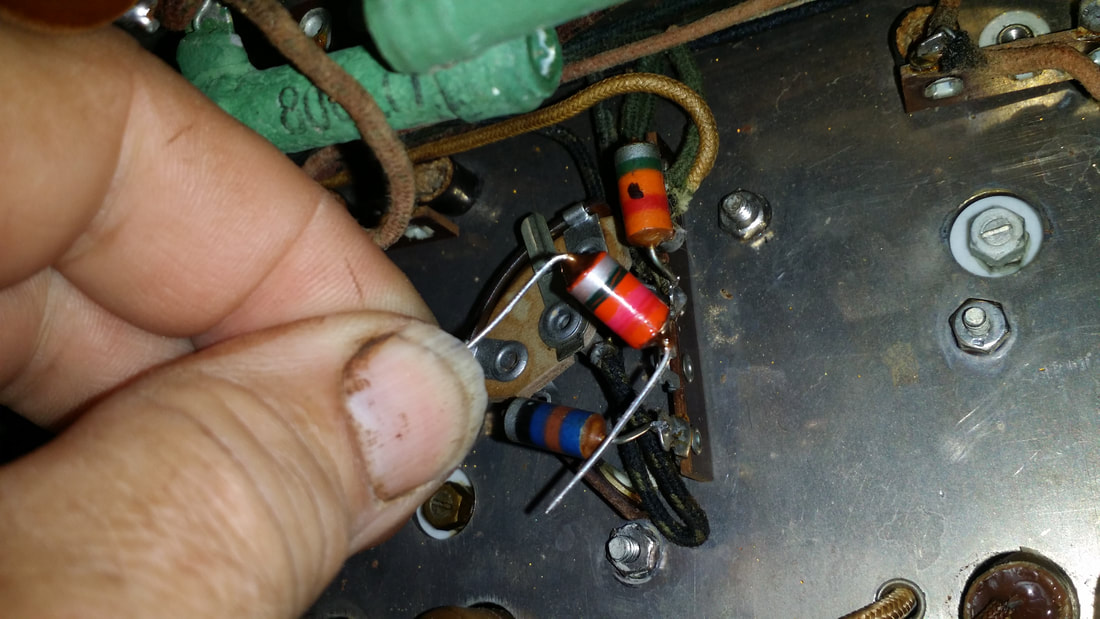
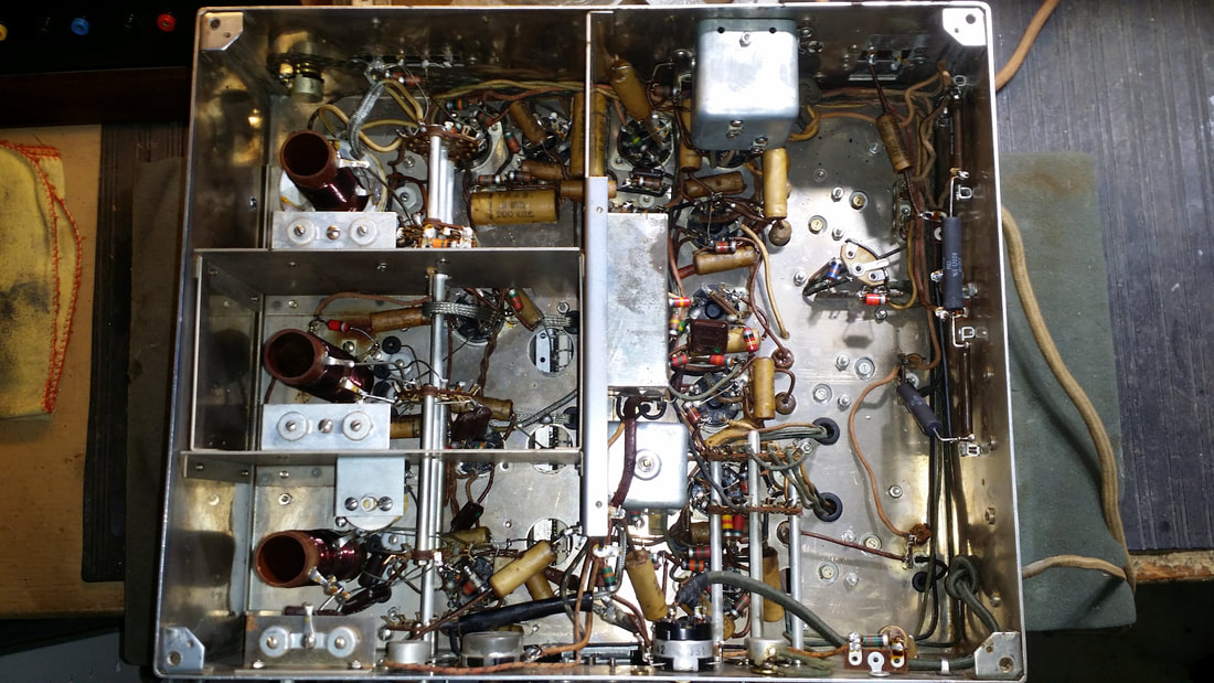
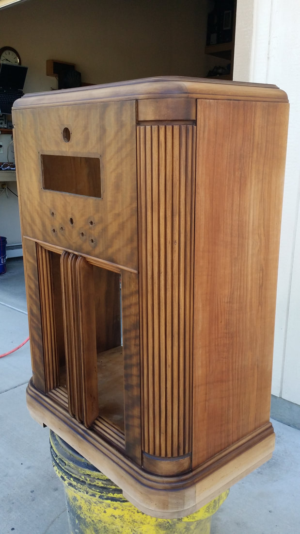
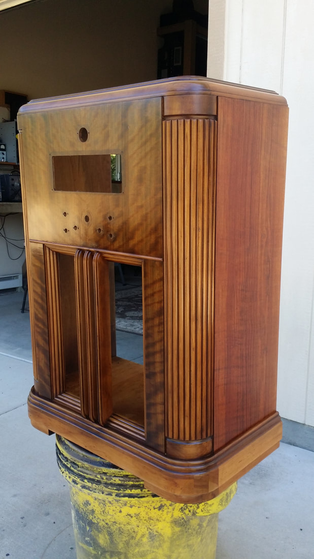
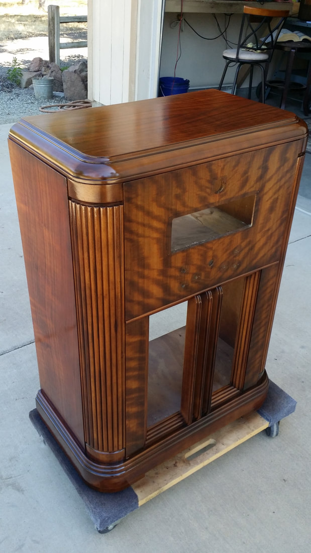
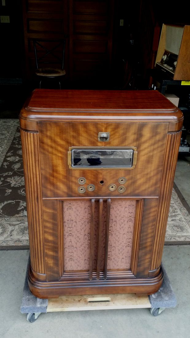
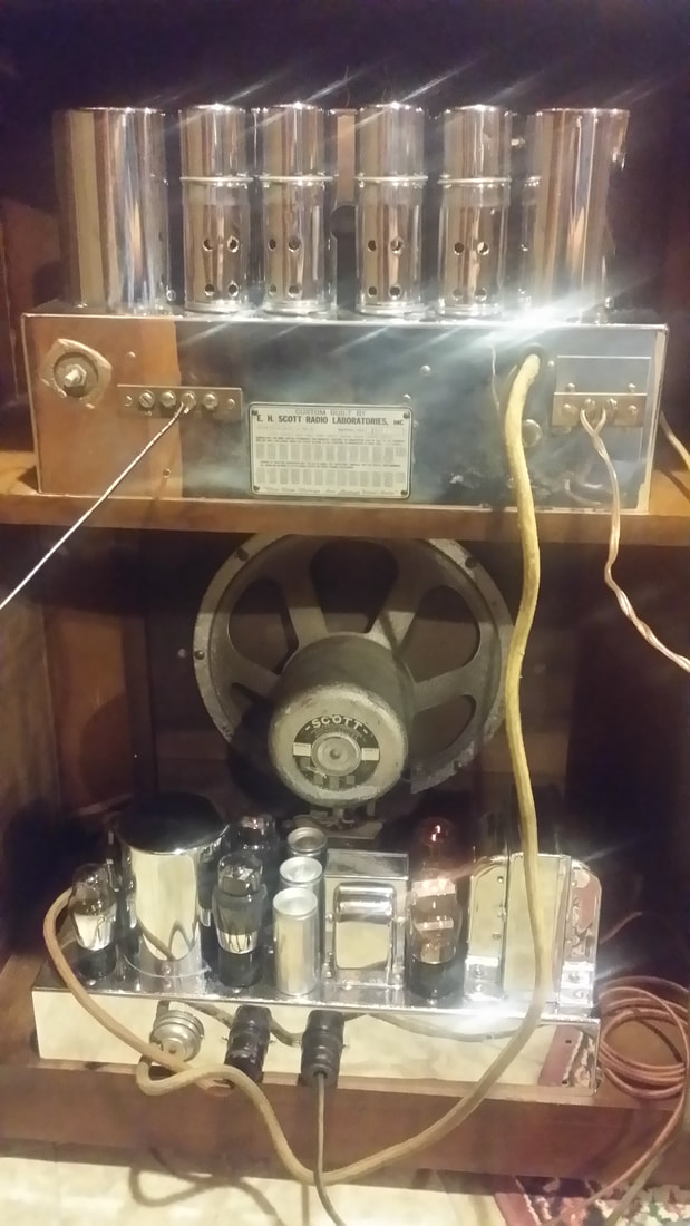
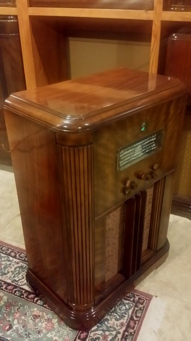
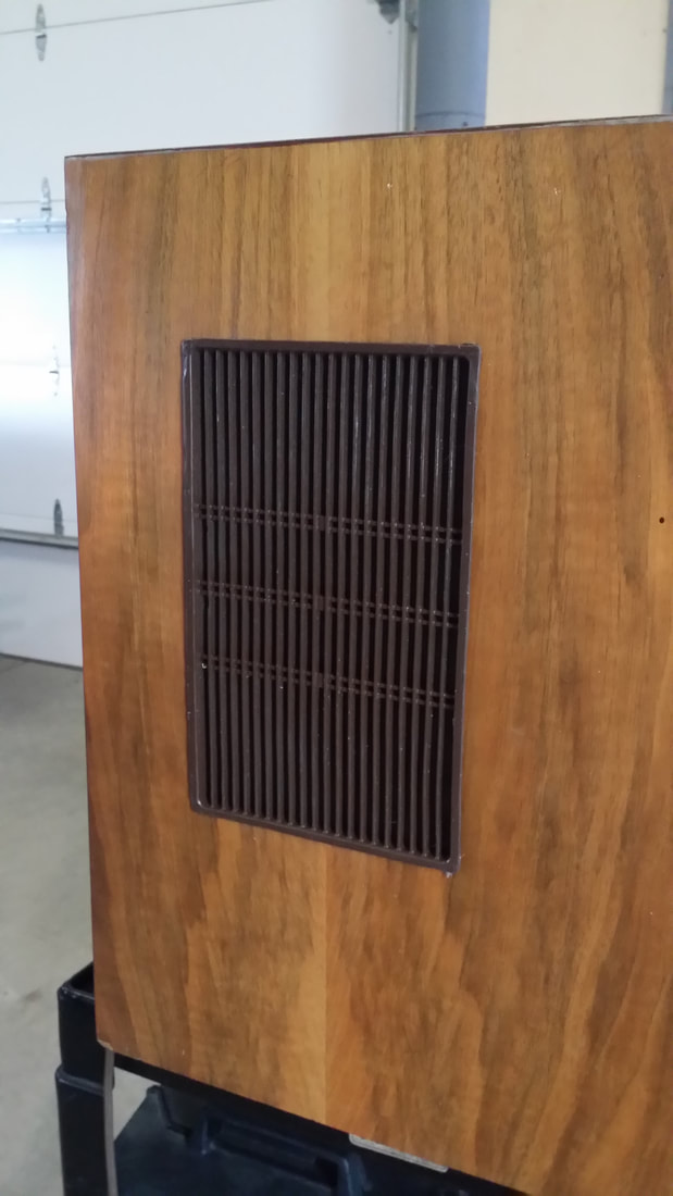
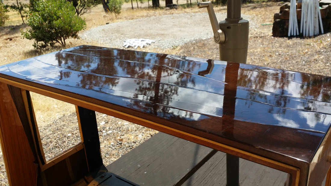
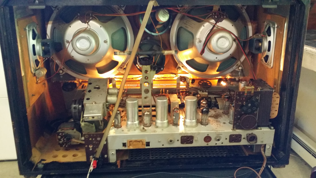
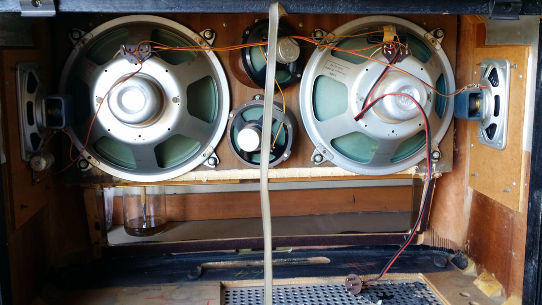
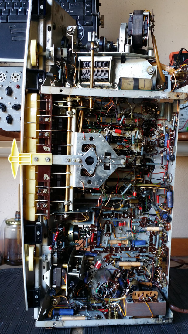
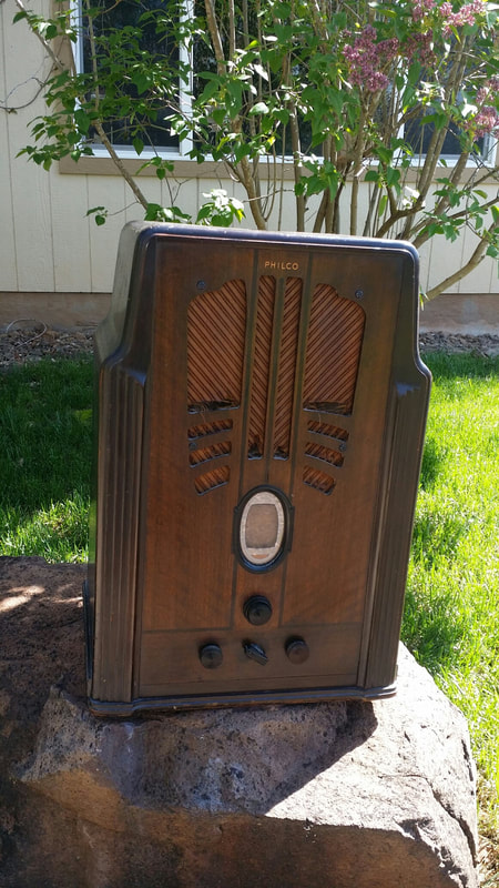
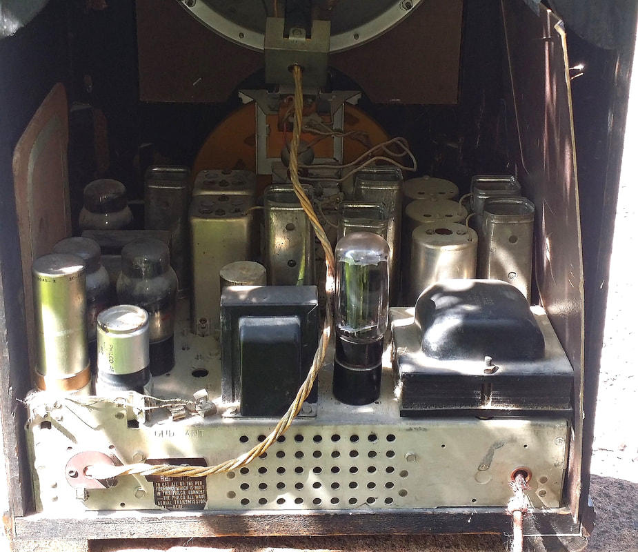
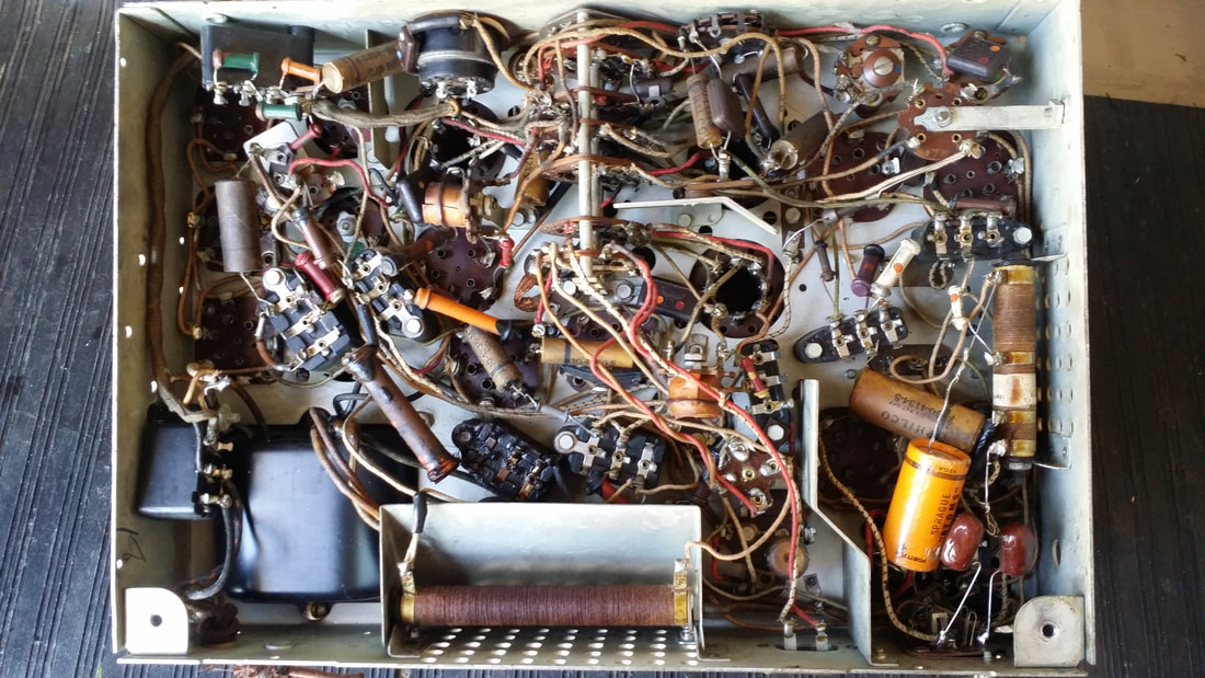
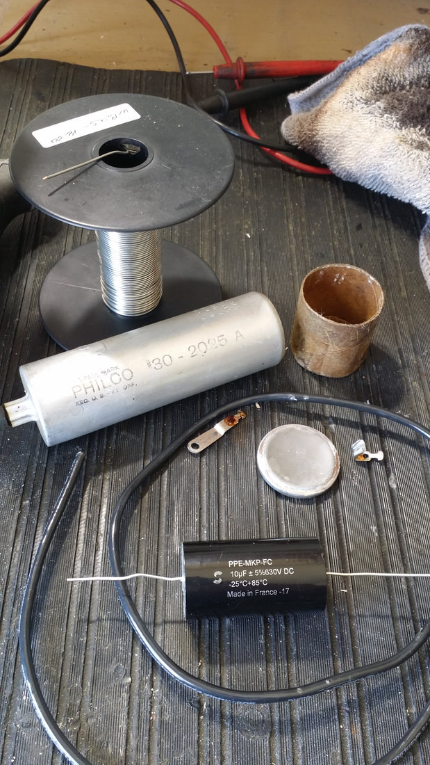
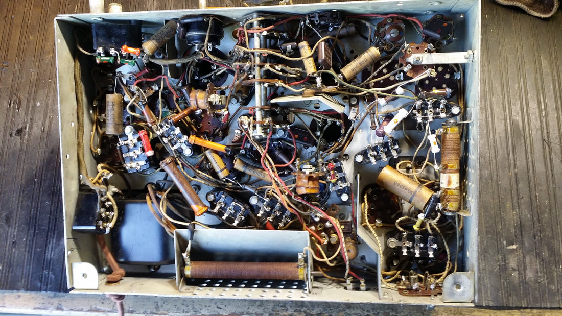
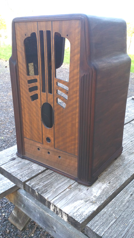
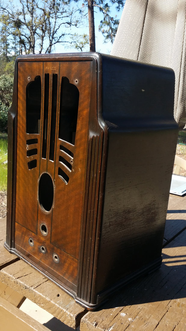
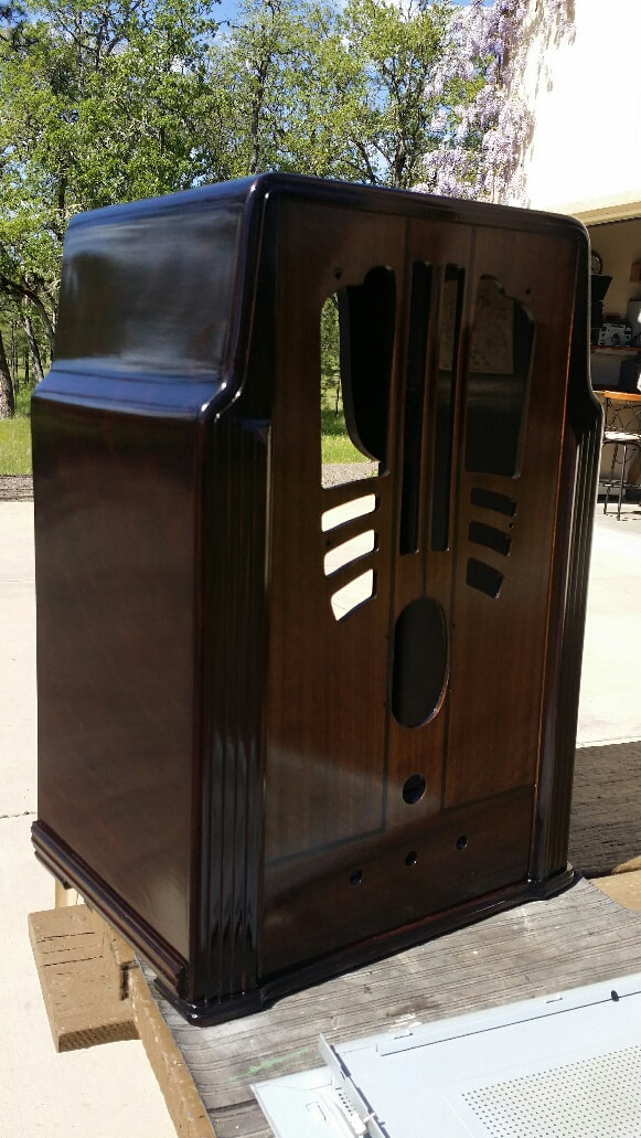
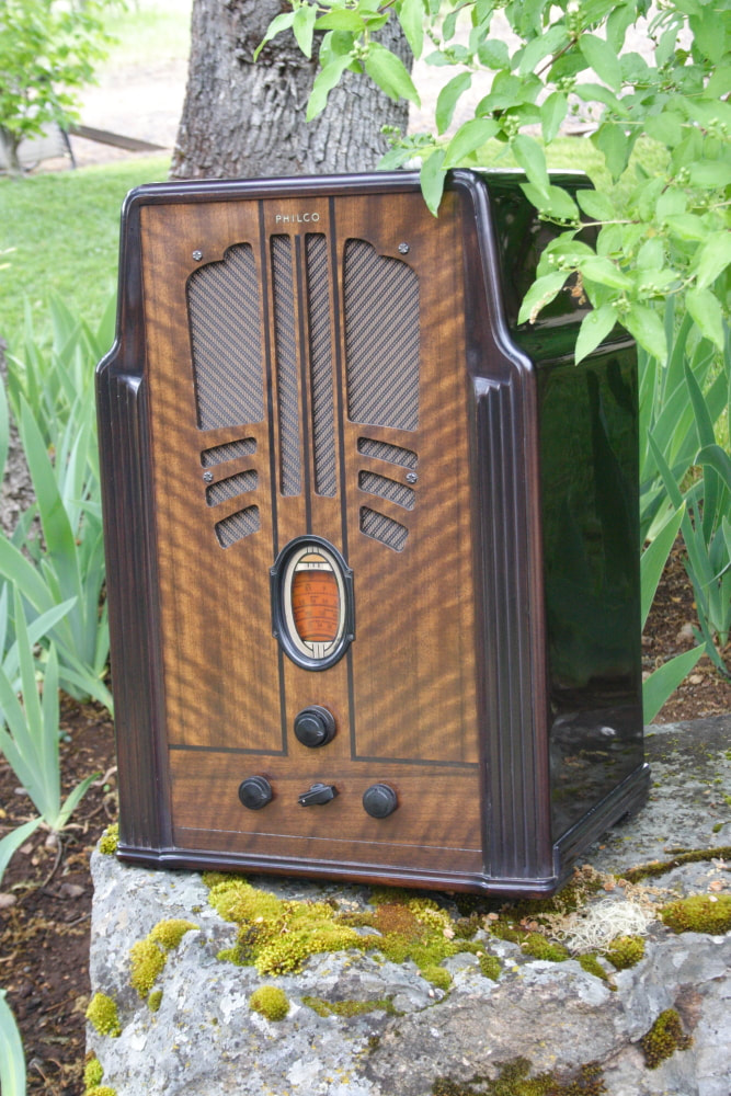
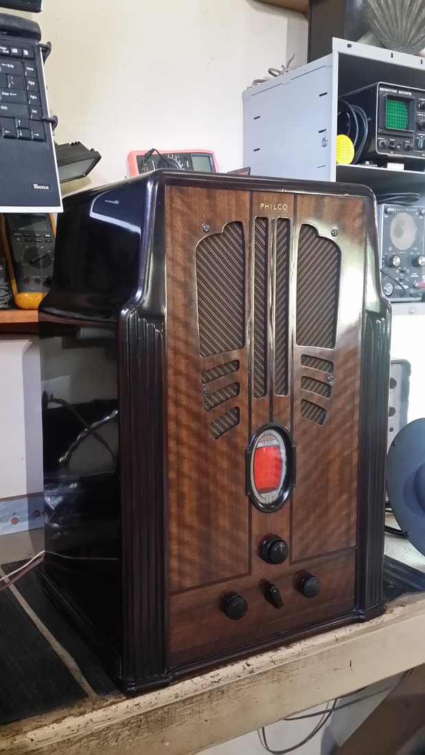
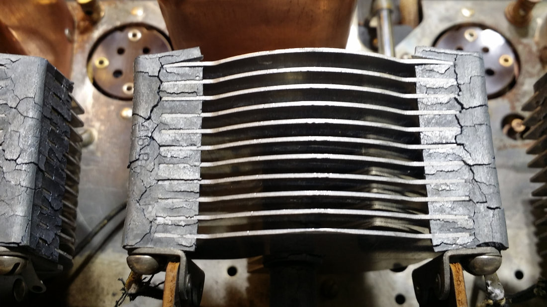
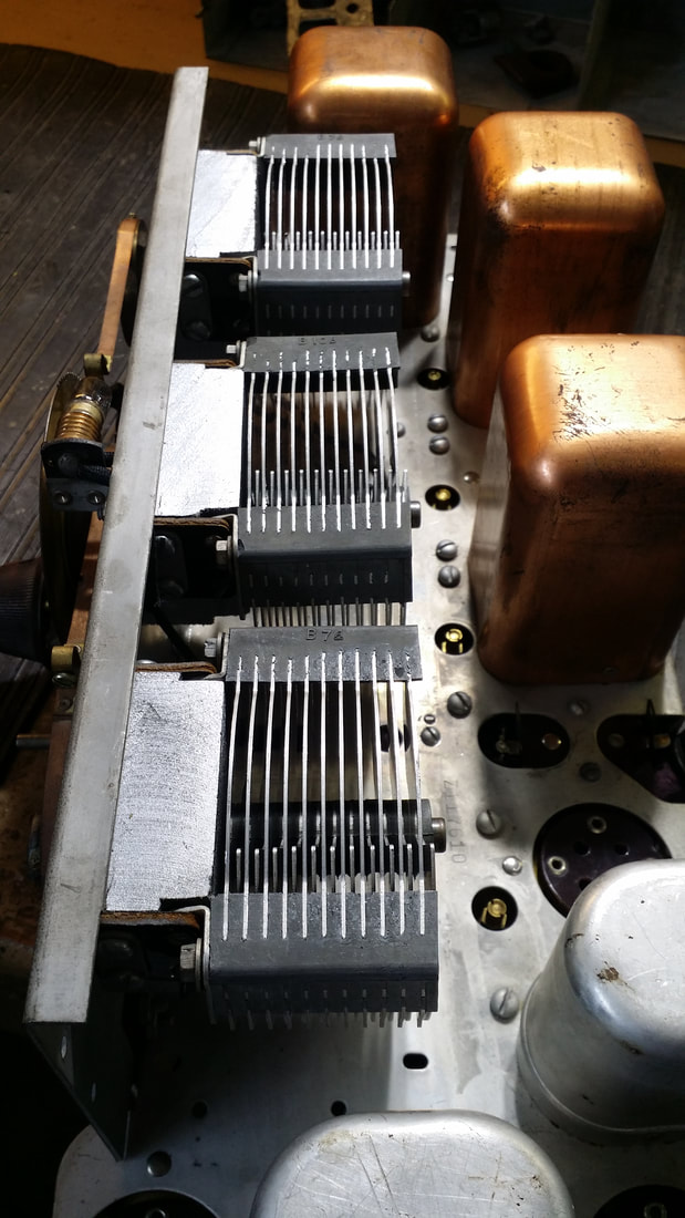
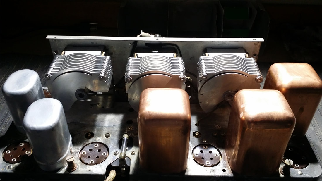
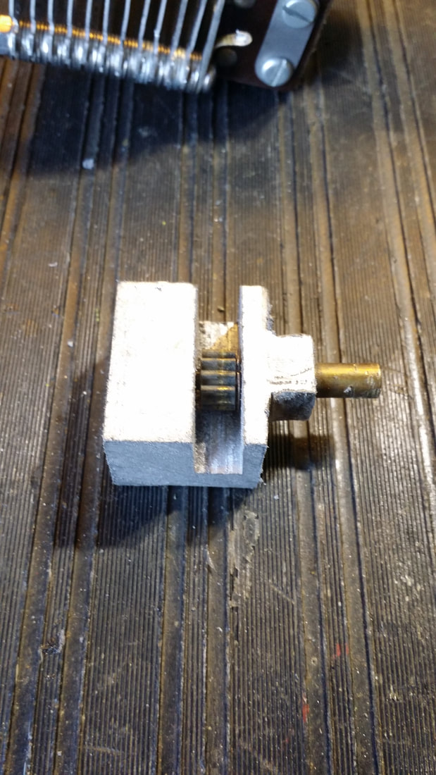
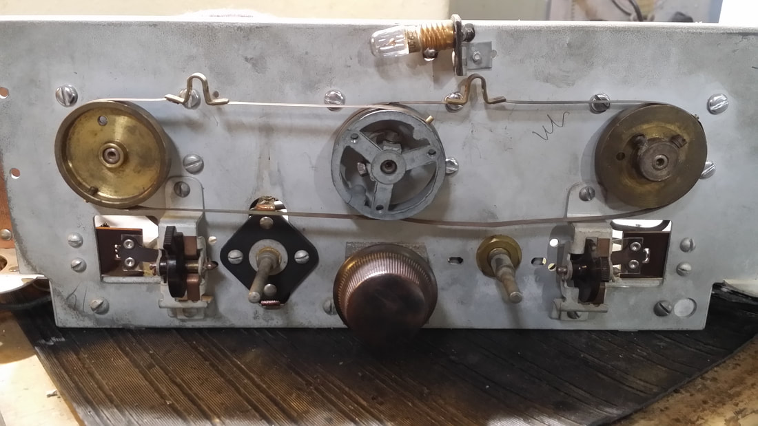
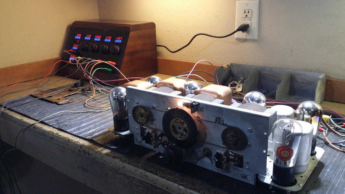
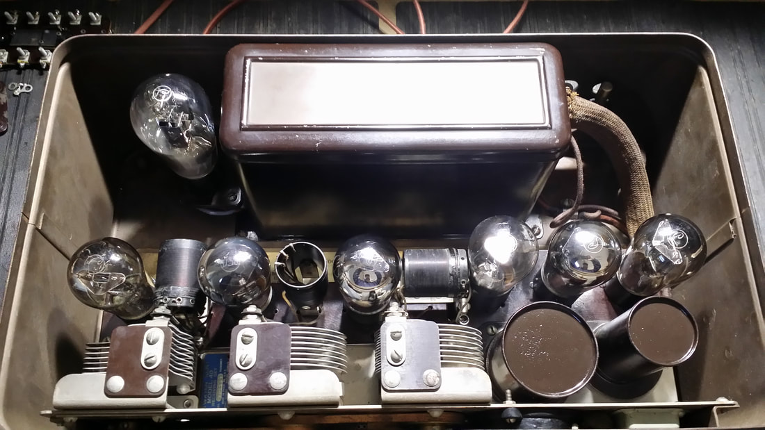
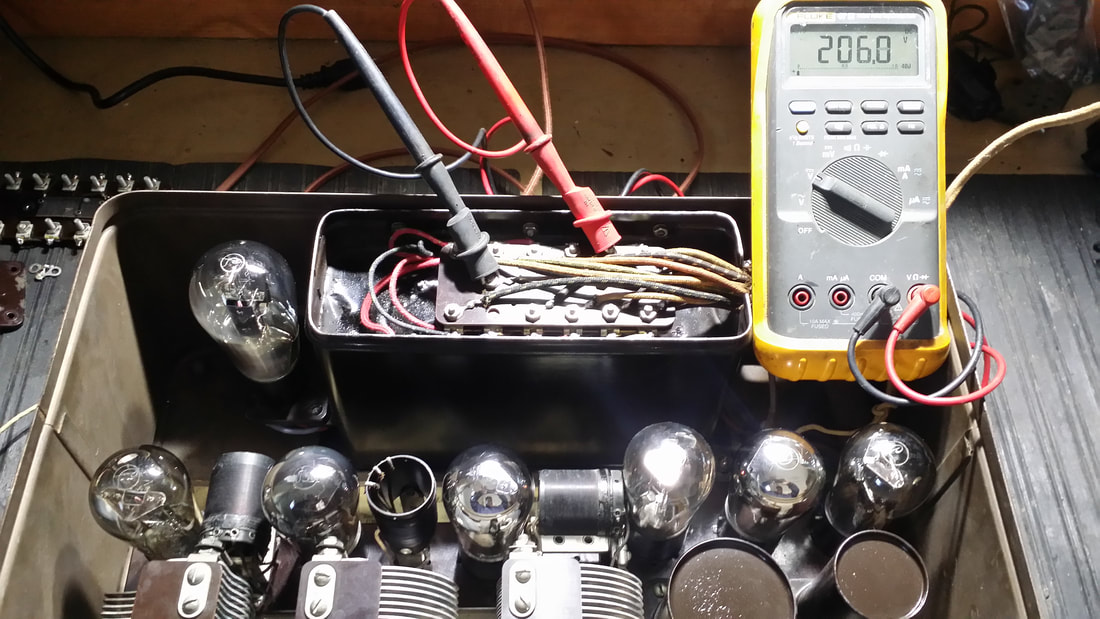
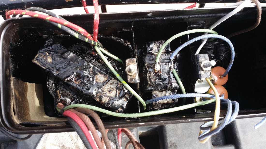
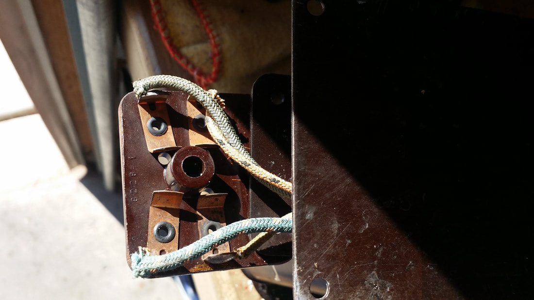
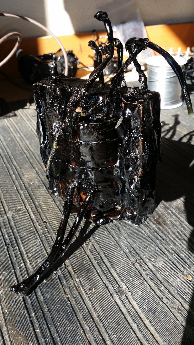
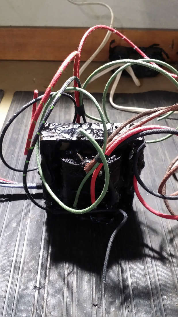
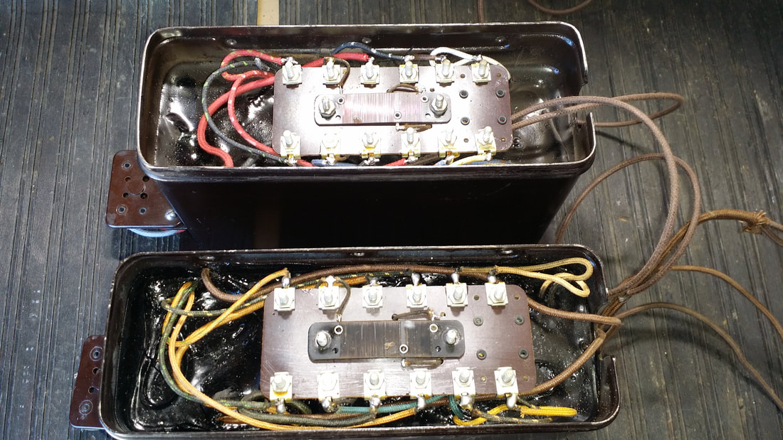
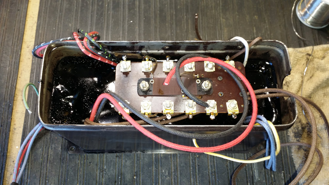
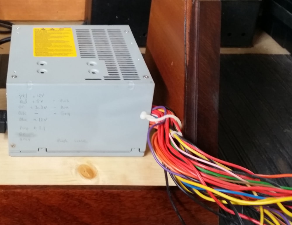
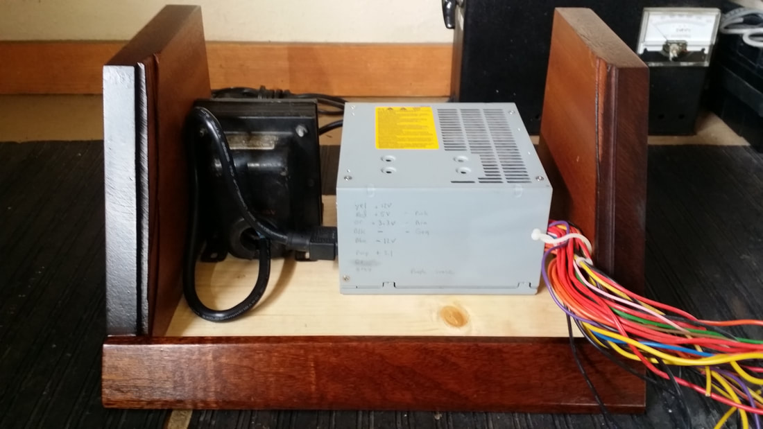
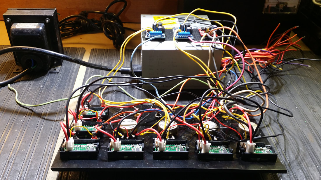
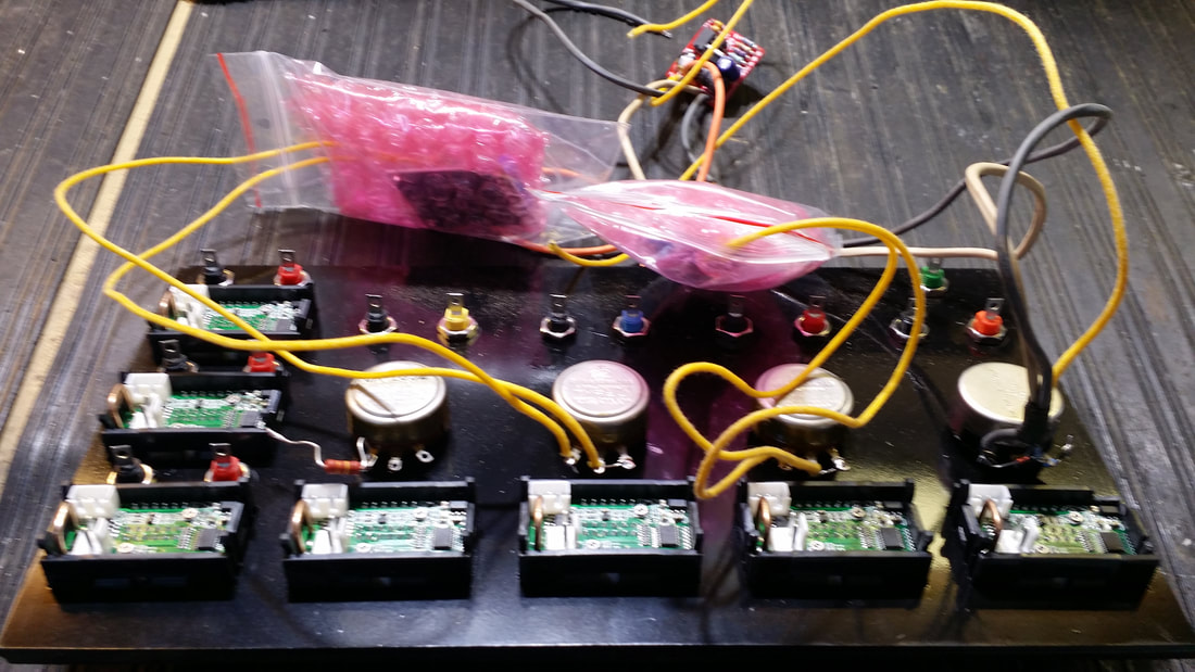
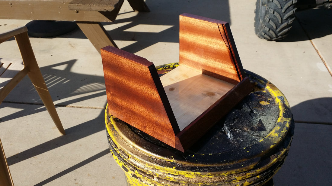
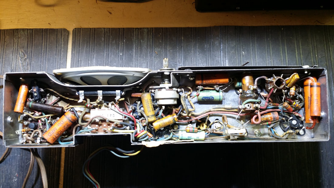
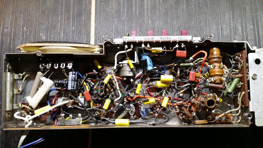
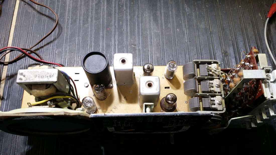
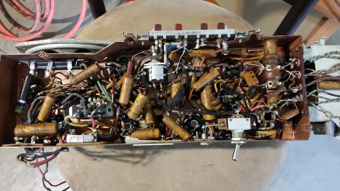
If there is an upside to to being somewhat confined to home, I have tunneled into the "wood shed" and extracted a couple of basket-case projects one of which is the the 1935 Western Air Patrol 5-tube Super pictured above. More later - -


 RSS Feed